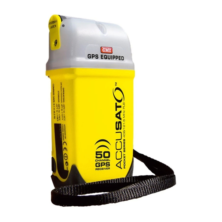
GME MT40 Series User manual

2
Applicability
•This presentation applies to the following models:
•MT400 [manually activated EPIRB, LiSO2 batteries]
•MT401 [manually & water activated EPIRB, LiSO2 batteries]
•MT403 [manually & water activated EPIRB, LiMnO2 batteries]
•MT403G [manually & water activated EPIRB + integral
GPS, LiMnO2 batteries]
•MT401FF [float-free EPIRB, LiSO2 batteries]
•MT403FF [float-free EPIRB, LiMnO2 batteries]
•MT403FG [float-free EPIRB + integral GPS, LiMnO2 batteries]

3
APPLICABLE MANUALS

4
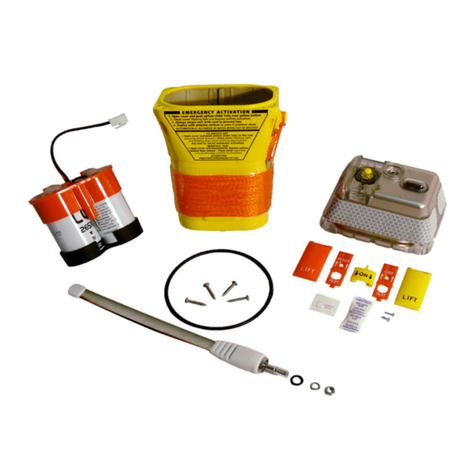
Service Kit Contents
MT400SVC
Note:all images show the
Batteries separate but
the kits will be delivered
with batteries fitted
inside the Lower
Chassis.
For reasons of economy,
the service kit is delivered
with both coloured covers
and both types of switch
slider track. Ensure you
use the one appropriate
to your product.

5
MT401SVC

6
MT403SVC

7
MT403GSVC
Note the different
cap assembly.

8
Tools And Equipment
•Philips Screwdriver –Size #1
•Hex Driver –7mm
•Anti-static Mat + wrist strap.
•Torque Screwdriver
•GME Dealer Leak-Test Kit P/N MT400DTK

9
Introduction
•To ensure extended lifetime of housings,
battery replacement also requires
replacement of the plastic housings and
the antenna. This procedure involves
several steps as listed in the next Slide,
individual description of operations is
detailed in following slides.

10
Disassembly / Assembly Sequence
•Inspection and Chassis disassembly
•Battery Pack Replacement
•Cap Disassembly
•Cap Assembly
•Replacement of desiccant
•Chassis Assembly
•Leak Test
•Slide switch and cover Installation
•Security seal replacement
•External labelling - replacement / update
•Transmission test and report
•Packing for return to customer

11
Inspection
•This operation is carried out to determine if the
beacon has suffered from physical or
environmental abuse which may indicate
potential board / component damage. Correct
electrical operation of the EPIRB is assessed.
•Carry out the inspections as outlined with the
Emergency Beacon, Inspection Pro forma
Drawing No. 42341. and complete the form,
noting all failures.

12
Chassis Disassembly
•Using a Philips screwdriver (Size #1)
remove four screws retaining the EPIRB
cap to the lower chassis. Discard the
screws.
•Holding the cap in one hand (not by the
antenna), pull on the lower chassis, to
separate. The fit is tight and “rocking” the
top case may be necessary. In extreme
cases, apply air pressure to the leak test
hole to separate the cap from the lower
chassis. ( refer to Leak-Test section )
•NOTE : For water activation models, the
water sensor contact on the circuit board
may momentarily touch the internal
metallic paint during withdrawal, causing
a beacon self test operation to occur. The
unit may continue to “beep” for 4 ~ 5
seconds. See Video clip 01

13
Battery Pack Replacement
•Two battery pack configurations containing cells of different chemistries are used
within this range of EPIRB; they are not interchangeable between model types.
( eg: ‘MT403’)
Verify the model type shown on the original
chassis.
Only the first five (5) characters are significant
for the purposes of determining which service kit
type is to be used;
(i.e. MT400, MT401, MT403 or MT403G)
WARNING: Is imperative that the correct battery service kit be used.
MT400SVC is for use only with ‘MT400’
MT401SVC is for use only with ‘MT401’ and ‘MT401FF’
MT403SVC is for use only with ‘MT403’ and MT403FF
MT403GSVC is for use only with ‘MT403G’ and ‘MT403FG’
Model
Type
See Video clip 02

14
•Record the expiry date (month
and year) marked on the top
face of the replacement battery
pack. You will need this later
when marking the battery
expiry on the exterior of the
beacon. See video clip 02
•Note: Depending on model
and or build date of the EPIRB
this information is either ink
stamped directly onto the
battery pack assembly housing
or provided as a sticker.
•Fully discharge the old battery
pack or dispose of it in
accordance with local
regulations
Date Mark

15
Cap Disassembly
• Disconnect the battery’s fly lead from the PCB by first
squeezing the latch release lever on the connector, then
withdrawing the connector housing vertically away from
the printed circuit board. Do not bend the connector pins.

16
•Use a 7mm hex driver to
undo the antenna
retention nut. Remove
and discard the nut and
spring washer.
•Separate the antenna
from the cap . Discard
both the antenna and the
o-ring seal .
•Carefully withdraw the
PCB from the cap and
place it on an antistatic
surface, discarding the
plastic cap assembly.
•See video clip 03
CAUTION: This equipment
contains static sensitive
components.. Handling
precautions required.

17
Cap Assembly
•Assembly can be carried out by
following the disassembly operations
in reverse sequence, also noting:
•Only new parts, supplied with the
Service Kit, must be used.
•Place each pcb edge into the guide
slot before inserting into the cap.
O-ring
Spring
washer PCB Guides

18
•During reassembly of GPS
equipped models, ensure the
GPS antenna cable is located
in the deeper groove as
shown opposite and carefully
align the Helix antenna
protruding from the leading
edge of the pcb with the
corresponding cavity
provided in the cap.
•See video clip 04
•Ensure that the spring washer is
in place beneath the antenna
retention nut before tightening to
95cNm (0.95Nm) using a 7mm
socket driver.

19
Replace Desiccant Sachet
•Remove the existing desiccant sachet
from the PCB exercising care not to
tear it (messy). Carefully remove any
remnants of the double-sided tape that
had previously retained the sachet in
place.
•Remove the desiccant sachet from the
sealed bag in which it was provided
and carefully remove the cover strip
from the double-sided adhesive strip
on the back
•Firmly press the desiccant against the
metal screening can, ensuring it
makes good contact and is securely
retained.
•See video clip 05
•IMMEDIATELY proceed without delay
to Chassis Assembly stage.

20
Chassis Assembly
•Fully seat the new o-ring in the
groove, ensuring it is fitted evenly
with no twists. A blunt instrument
may be of assistance in this
matter. Whichever tool is used
ensure that it does not damage
the face of the o-ring seal.
•There is only one correct
orientation with which the cap and
lower chassis will correctly mate.
Ensure that the guides provided
around the lip of the lower chassis
mate with the corresponding
ridges provided on the cap (2 on
one long side, one on the other).
This manual suits for next models
7
Table of contents
Other GME Security System manuals