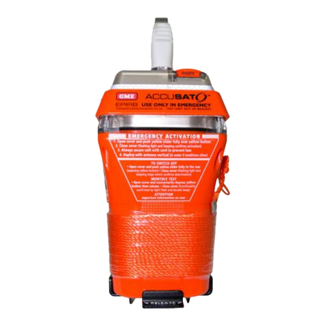
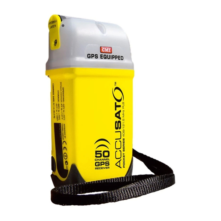
GME MT400 Operating manual

TECHNICAL SERVICE
MANUAL
406MHz COSPAS-SARSAT Emergency Beacon,
MT400 Series EPIRB
Order Part Number: 310433
Drawing Number: 42772
Issue: 6
Status: Released
Date: 09-JUL-2018
Change History: 8235
17 Gibbon Road, Winston Hills NSW 2153, Australia
ABN: 93 000 346 814
gme.net.au
GME Pty Ltd
This document and the information contained
herein is the property of GME Pty Ltd. It may
not be copied, used or disclosed in whole or
in part except with prior permission of GME
Pty Ltd. It is supplied without liability for
errors or omissions.

2 TECHNICAL SERVICE MANUAL
APPLICABILITY
This document applies to the following models:
• MT400 [manually activated EPIRB, LiSO batteries]
• MT401 [manually & water activated EPIRB, LiSO batteries]
• MT403 [manually & water activated EPIRB, LiMnO batteries]
• MT403G [manually & water activated EPIRB + integral GPS, LiMnO batteries]
• MT401FF [float-free EPIRB, LiSO batteries]
• MT403FF [float-free EPIRB, LiMnO batteries]
• MT403FG [float-free EPIRB + integral GPS, LiMnO batteries]
SCOPE
Service Department level maintenance is outlined within this document. A suitable skill level is
assumed, as is access to common electronic and mechanical tools.
The scope of this document is limited to servicing and repair in any one or more of these cases:
• Inspection and performance check,
• Battery replacement, typically due to use or life expiry,
• Replacement of physical parts which may have been damaged or have deteriorated to a
point of no longer being serviceable,
• Exchange of a printed circuit card assembly that has failed in a manner not covered by the
product warranty (i.e. a non-electrical failure due to leakage or physical damage only).
NOTE:Repair of the printed circuit card assembly is not possible at the distributor level;
replacement of components is likely to affect module calibration. Specialist fixtures and facilities
only available at the factory are required to perform a module alignment after any repair
operation.
Additional servicing requirements may be imposed by other organisations and authorities on
particular users and installations (e.g. IMO/Circ. 1039). Such requirements are outside the scope
of this document and it is the responsibility of the agent carrying out the inspection and/or
service to determine which if any may apply. These requirements where applicable are always in
addition to, and do not replace, any of the requirements specified within this document.
ASSOCIATED DOCUMENTS
Reference to additional internal and external material may be required to complete some of the
operations detailed within this manual.
Furthermore, from time to time Technical Service Bulletins (TSBs) may also be released. These
bulletins contain information, which may be important to the continued service of specific
beacons, and the instructions contained therein must be followed.
It is possible to regularly verify the issue status and download as necessary new document
releases including TSBs via the support area on GME’s website. Always work with the latest
versions of this and other documentation.
GME’s home page web address is: www.gme.net.au
As information access is limited to approved organisations, distributors and dealers, you must
first apply for an account login. You can do this online from the SUPPORT page.

TECHNICAL SERVICE MANUAL 3
PRODUCT MAINTENANCE & SERVICE
4.1 INTRODUCTION
A number of service actions are identified within this manual, more than one may be applicable
at any beacon service. Please familiarise yourself with all available service actions to ensure that
a complete service is carried out.
Only manufacturer-authorised spares and components are approved for use in carrying out the
service operations contained here-in.
Access to a range of service tools is assumed. Particular specialised tools are listed in Table 6-5).
A dry, pressurised air source is required for leak testing.
4.1.1 MODEL VARIANTS
Please be aware the pictorial representations shown in a particular service operation step
may not always precisely depict all model variants or build revisions. In situations where this
detail discrepancy is important to the actions being described, it shall be addressed by a note,
alternate picture, or both.
4.2 BATTERY SERVICE KITS
These illustrations show the contents of the battery service kits.
The images show the batteries separate but the kits will be delivered with batteries fitted inside
the lower chassis.
For reasons of economy, the service kit is delivered with both coloured covers and both types of
switch slider track. Ensure that you use the one appropriate to your product.
4.2.1 MT400 SERIES BATTERY SERVICE KIT
These illustrations show the contents of the battery service kits.
The images show the batteries separate but the kits will be delivered with batteries fitted inside
the lower chassis.
For reasons of economy, the service kit is delivered with both coloured covers and both types of
switch slider track. Ensure that you use the one appropriate to your product.
Orange
activation
cover, MT401
slider track,
Slide switch,
MT400 slider
track, Yellow
activation
cover
Cap
4 screws for
securing the cap
to the chassis
Spring
Washer
Retention Nut
O-ring Seal
Antenna
O-ring Seal
Battery
Security seal,
Desiccant, Leak test
point screw (pan
head), Retention
screw (countersunk)

4 TECHNICAL SERVICE MANUAL
4.2.2 MT401 SERIES BATTERY SERVICE KIT
Part names are as for the MT400 series battery service kit, see above at Section 4.2.1.
4.2.3 MT403 SERIES BATTERY SERVICE KIT
Part names are as for the MT400 series battery service kit, see above at Section 4.2.1.

TECHNICAL SERVICE MANUAL 5
4.3 REPAIR MATRIX
The sequence of operations for each service type is given within Table 4-1. Multiple service types
may be combined provided the sequence of operations is maintained.
Para. Operation/ Nature of service Routine
inspection
Battery
Replace-
ment
External
Repair of
Fault
4.4.1 Inspection
4.4.2 External Switch Mechanism x x
4.4.3 Chassis Disassembly / Assembly,
including battery replacement xx
4.4.4 Cap Disassembly / Assembly x x x
4.4.5 Replacement of Desiccant Sachet xx
4.4.6 Leak Test
4.4.7 Security Seal Replacement
4.4.8 Reprogramming User Information xx
4.4.9 External Labelling Replacement /
Update
4.4.10 Produce Beacon Record
4.4.11 Transmission Test and Report
4.4.12 Packing for Return to Customer
KEY
This operation must be carried out
May be required depending on circumstances, refer to test criteria
xNot required.
4.4 SERVICING OPERATIONS
4.4.1 INSPECTION
This operation is carried out to determine whether the beacon has suffered from physical
or environmental abuse that will require rectification prior to its return into service. Correct
electrical operation of the EPIRB is assessed.
1. Carry out the inspections as outlined with the Emergency Beacon, Inspection Proforma
Drawing No. 42341.
2. Complete the form, noting all failures.

6 TECHNICAL SERVICE MANUAL
4.4.2 EXTERNAL SWITCH MECHANISM
This operation is carried out when:
• Access to the sealing screw is required.
• The switch mechanism or switch cover needs to be replaced.
Disassembly
For disassembly each step is to be completed in numerical order as follows:
1. Move the beacon activation switch to the ON position.
Note: IMMEDIATELY move on to and complete the next step.
2. Remove the screw and then the slider track completely from the beacon.
Assembly
To re-assemble and/or replace components each step is to be completed in numerical order as
follows:
1. Push the switch slider on to a slider track appropriate to the beacon model type.
MT400 type has
‘OFF’
Leave this hole
exposed when fitting
the switch slider
MT401type
has ‘READY’
2. Locate the switch and switch slider track so that the tongue provided on that track engages
into the slot provided at the front of the beacon cap. Place and then hold in position the
switch cover of the type appropriate to the beacon model type as shown.
WARNING: At this point, the switch is on. You must complete the next steps within 45 seconds
to avoid a live transmission.
Yellow switch covers are fitted to yellow
coloured beacons
Orange switch covers are fitted to orange
coloured beacons

TECHNICAL SERVICE MANUAL 7
3. Place and tighten the countersunk retention screw to a torque of 50 cN·m ± 5 cN·m.
4. Move the slider switch to the OFF or READY position.
WARNING: You must do this within 45 seconds to avoid a live transmission.
5. Close the switch cover.
4.4.3 CHASSIS DISASSEMBLY / ASSEMBLY, INCLUDING BATTERY REPLACEMENT
This operation is carried out in any of these cases:
• Internal access to the beacon is required
• A mechanical repair requires the EPIRB cap and chassis to be separated.
• The battery requires replacement
The EPIRB battery should be replaced when any of the following is evident or has occurred:
• The battery has reached (or exceeded) its expiry date or would otherwise reach its expiry in
the near term,
• The beacon has been activated or is suspected of having been activated, and/or
• The battery pack has failed or is considered suspect.
WARNING: Always use the correct battery service kit.
• MT400BAT is for use only with MT400
• MT401BAT is for use only with MT401
• MT403BAT is for use only with MT403
To carry out the replacement you will need the applicable battery service kit; these kits include
battery pack, cap, chassis, ballast and miscellaneous items. See 4.2, Battery service kits, starting
on page 6.
Disassembly
For disassembly, each step is to be completed in numerical order as follows:
1. Ensure that you are using an antistatic mat and wearing the wrist strap.
CAUTION: This equipment contains static-sensitive componentry. Handling precautions are
required and an antistatic wrist strap must be worn.

8 TECHNICAL SERVICE MANUAL
2. Using a PH1 Phillips screwdriver, remove all four screws that retain the EPIRB cap to the
lower chassis. Discard the screws .
3. Firmly grasp the cap with one hand (not by the antenna), and the lower chassis with the
other hand, and fully separate them. The fit is reasonably tight and it may sometimes be
necessary to rock the two components in respect to each other to initiate the separation
process.
In extreme cases, apply air pressure to the leak test point to separate the cap from the lower
chassis. (Refer to 4.4.6, Leak Test.)
For water activation models the water sensor interface on the circuit board may momentarily
touch the metallic paint on the lower chassis during withdrawal, causing a beacon self test
operation to occur. The unit “may “beep” for 4–5 seconds.
WARNING: (Water Activated Models): If the cap and lower chassis are left only partially
separated sensor interface contact with the lower chassis may cause the beacon to activate after
50 seconds.
4. Extract the O-ring seal from the groove around the cap and discard it.
5. Disconnect the battery’s fly lead from the printed circuit board (PCB) by first squeezing the
latch release lever on the connector, and then withdrawing the connector housing vertically
away from the printed circuit board.
Take care not to bend the connector pins.
6. Using a PH2 Phillips screwdriver, undo and remove the screws which retain the battery pack
in the base of the EPIRB.

TECHNICAL SERVICE MANUAL 9
7. Fully discharge the old battery pack and dispose of it in accordance with local regulations.
Assembly
Assembly consists of essentially the disassembly operations in reverse sequence. Each step is to
be completed in numerical order as follows:
1. Ensure that you are using an antistatic mat and wearing the wrist strap.
CAUTION: This equipment contains static-sensitive componentry. Handling precautions are
required and an antistatic wrist strap must be worn.
2. Verify the model type shown on the original chassis.
Only the first five (5) characters are significant for the purpose of determining which service
kit type is to be used (that is, MT400, MT401 or MT403).
3. Obtain the correct battery service kit. Refer to Table 6-3 for ordering details.
4. Inspect all components for damage and replace as necessary.
You must always replace the O-ring seal located in the groove around the cap with a new
one prior to assembly of the beacon.
5. Note down the expiry date (month and year) marked on the top face of the replacement
battery pack. You will need this later when marking the battery expiry on the exterior of the
beacon.
Note: Depending on model and or build date of the EPIRB this information is either ink
stamped directly on to the battery pack housing or provided as a sticker.
Battery
expiry date
ink stamping
Battery
expiry
date
sticker

10 TECHNICAL SERVICE MANUAL
6. Fully seat the new O-ring in the groove, ensuring it is fitted evenly with no twists. A blunt
instrument may be of assistance. Whichever tool is used ensure that it does not damage the
face of the O-ring seal.
7. Connect the battery’s fly lead to the PCB.
8. There is only one correct orientation which allows the cap and lower chassis to correctly
mate. Ensure that the guides provided around the lip of the lower chassis mate with the
corresponding ridges provided on the cap (two on one long side, one on the other).
9. When mating the cap and lower chassis together, ensure that the 2 tongues provided on the
lower edge of the printed circuit board (PCB) module engage centrally within the respective
guides provided on the top face of the battery pack. Failure to do so will result in the PCB
unacceptably flexing when the cap and lower chassis are assembled together. A PCB so
flexed must be considered unserviceable.
10. Tighten all 4 screws securing the cap to the chassis evenly before finally tightening each
screw to a torque of 100 cN·m ± 10 cN·m.
Single rib on
chassis
Double rib on
chassis

TECHNICAL SERVICE MANUAL 11
4.4.4 CAP DISASSEMBLY / ASSEMBLY
This operation is carried out when:
• The external antenna and/or seal need to be replaced.
• It is necessary to remove the electronic module from the cap.
• Access to the internal switch assembly, including the sealing membrane is required.
Disassembly
For disassembly, each step is to be completed in numerical order as follows:
1. Ensure that you are using an antistatic mat and wearing the wrist strap.
CAUTION: This equipment contains static-sensitive componentry. Handling precautions are
required and an antistatic wrist strap must be worn.
2. Use a 7 mm hex driver to undo the antenna retention nut. Remove and discard the nut and
spring washer.
3. Separate the antenna from the cap.
4. Discard the antenna and the O-ring seal that is present at the interface between the two.
5. Carefully withdraw the PCB from the cap, place it on an antistatic mat.
6. Discard the cap.
Assembly
For assembly each step is to be completed in numerical order as follows:
1. Inspect all components for damage and replace as necessary.
2. Ensure that you are using an antistatic mat and wearing the wrist strap.
CAUTION: This equipment contains static-sensitive componentry. Handling precautions are
required and an antistatic wrist strap must be worn.
3. Fit the O-ring seal to the bolt at the base of the new antenna. Push the bolt through the
hole provided in the cap.
O-ring
Spring washer
Retention nut

12 TECHNICAL SERVICE MANUAL
4. Fit the spring washer and the retention nut to the antenna base.
5. Using a 7 mm hex socket driver, tighten the antenna retention nut to 95 cN·m ± 5 cN·m.
6. Install the PCB. Note the guide slots in the cap; locate the PCB edges into these guide slots
before inserting the PCB into the cap.
PCB Guides
7. During reassembly of GPS equipped models, ensure that the GPS antenna cable is located in
the deeper groove and carefully align the helix antenna protruding from the leading edge of
the PCB with the corresponding cavity provided in the cap.
4.4.5 REPLACEMENT OF DESICCANT SACHET
The desiccant sachet must be replaced whenever:
• the beacon has been opened
• the integrity of the case has been compromised
All steps are to be completed in numerical order as follows:
1. Remove the existing desiccant sachet from the PCB exercising care not to tear it as the
contents may spill. Carefully remove any remnants of the double-sided tape that had
previously retained the sachet in place.
2. Remove the desiccant sachet from the sealed bag in which it was provided.
WARNING: If the sachet is exposed to open air for longer than a few minutes, its eventual
capacity to absorb moisture within the beacon will be compromised.
3. From the rear of the sachet carefully remove the cover strip from the double-sided adhesive
strip provided.
4. At the location shown, firmly press the desiccant against the metal screening can, ensuring
it makes good contact and is securely retained.

TECHNICAL SERVICE MANUAL 13
Sachet Location
5. IMMEDIATELY reseal the EPIRB (4.4.3).
6. Perform a leak test (4.4.6) including insertion of the sealing screw.
4.4.6 LEAK TEST
It is vitally important that the integrity of all environmental seals remains intact. Perform this test
where:
• The EPIRB chassis has been opened for access or repair purposes, or
• A beacon’s continued performance in this respect is to be verified prior to placing it back
into service.
Notice that on the top of the EPIRB, near the top right corner, visible when you remove the
activation cover and switch mechanism, is a small hole, normally blocked by a pan-head screw.
This is the test point. The aim of the test procedure is to apply dry air at a pressure of 1.0 bar ±
0.1 bar to the test point, immerse the EPIRB in water, and check for leaking air bubbles.
WARNING: All water activated models such as MT401 and MT403 series (including float free
variants) will automatically activate and transmit a distress message if placed in water.
Please refer to the necessary precautions detailed below.
Usually during this test the EPIRB (sometimes referred to as the Unit Under Test, or UUT)
will be in water for more than 60 seconds, and thereby on water-activated models, you risk
transmitting a false distress alert.
In normal use the manual release and float free housings for these models contain magnets
which interact with beacon circuitry to disable water activation when stowed. The Dealer Leak
Test Kit (MT400DTK; refer to Table 6-4) is similarly equipped with a defeat magnet.
All steps are to be completed in numerical order as follows:
1. If they are present, remove the activation cover, slide switch and sealing screw from the
EPIRB.

14 TECHNICAL SERVICE MANUAL
2. Assemble the Dealer Leak Test Kit. Refer to the instructions (part number 310463).
3. Place the EPIRB in the Dealer Leak Test Kit and apply compressed air as described in the
instructions (part number 310463).
4. Completely submerse the EPIRB in fresh water and allow any externally trapped air to
surface.
5 Observe for a minimum of 30 seconds and verify that no air bubbles escape from inside the
EPIRB.
Observe in particular the following locations:
• Joint between cap and chassis
• Joint between cap and antenna
• Joint between cap and plunger
• Joints between chassis and water sensors (for water-activated models)
If any air bubbles escape, the EPIRB fails the leak test.
If there is no sign of leakage, the EPIRB passes the leak test.
6. Remove the EPIRB from the water and from the cradle, as described in the Dealer Leak Test
Kit instructions (part number 310463).
7. Using compressed air, blow clear any water from near the test point.
8. If the EPIRB has passed the leak test, the test point must now be blocked. Apply sufficient
(but not excessive) silicone sealant into the test point to promote a good seal.
WARNING: Use only a neutral (that is, not acidic) cure silicone sealant.
Immediately insert and then tighten the test point sealing screw to 30 cN·m ± 5 cN·m torque,
before the sealant begins to cure.

TECHNICAL SERVICE MANUAL 15
9. Fully dry the exterior of the EPIRB using an absorbent cloth and/or air gun, as required.
10. If the EPIRB has passed the leak test, Re-install the slide switch and activation cover.
If the EPIRB has failed the leak test, it must not be returned to service. It may be necessary to
obtain another battery service kit. If it appears that only individual parts are required, check for
availability with GME.
4.4.7 SECURITY SEAL REPLACEMENT
A failed or torn security seal may lead the owner to question the operational status of the
EPIRB. Some repair operations result in destruction of the original seal thereby necessitating its
replacement.
Where an EPIRB is returned for assessment and its seal is intact, but in deteriorated condition,
it is recommended that a replacement seal be provided to extend its life through to the next
inspection.
All steps are to be completed in numerical order as follows:
1. Clear away all remnants of the previous seal. DO NOT use cleaning products that may attack
the plastics.
2. Carefully place the replacement seal ensuring that the two tabs on the switch mechanism
fall within the cut-out slot.
3. Press down on the seal to ensure good and complete contact with the beacon.
4. Inspect the seal, and if it has torn during installation a new seal must be installed.

16 TECHNICAL SERVICE MANUAL
4.4.8 REPROGRAMMING USER INFORMATION
Where the printed circuit board has been replaced, it is necessary to re-enter user preferences
and requirements relating to the selected C-S Protocol.
A Dealer Programming kit (part number MT400DPK) is required for this operation (refer Table
6-4).
NOTE: The serial number (S/N) reported by the programming software directly relates to the S/N
of the PCB. If you change the PCB the EPIRB S/N has also changed. If the customer wishes to
use the Serial User Protocol with the “Manufacturer Serial Number and TAC” then the beacon
fitted with a replacement PCB must be re-registered with the applicable authority.
This number is
uniquely determined
by the S/N of the
PCB fitted within the
EPIRB.
4.4.9 EXTERNAL LABELLING REPLACEMENT / UPDATE
New external labelling will need to be generated:
• If the beacon message programming has changed
• If the beacon’s PCB has been exchanged
• If labels are damaged or weathered
• If new batteries have been fitted and the expiry date needs to be updated to reflect this.
The following specialist items are required to complete this operation:
• Dealer Programming kit (P/N MT400DPK),
• Brother P-touch 2420 PC (or equivalent) laminated label printer, and
• laminated label stock as applicable to the labels printed.
Follow the operating instructions contained within the kit.
NOTE for USA only:
• If a new chassis is being used it is necessary to apply a NOAA registration label (part
number 400732) over the heat shrink retaining the lanyard (beacon front activation
instruction side).
• Verify that the FCC ID applicable to the model is present on the side of the chassis under
the area ‘APPROVED BY COSPAS-SARSAT’. If the FCC ID is not present, use the laminated
label printer to produce a label of no less than 10 pt character height with the FCC ID
details. Apply it firmly to the rear of the beacon on the unused area between ‘WARNING’
and manufacturer details.

TECHNICAL SERVICE MANUAL 17
4.4.10 PRODUCE BEACON RECORD
A Dealer Programming kit (P/N MT400DPK) is required for this operation (refer Table 6-4).
Follow the operating instructions contained within the kit.
4.4.11 TRANSMISSION TEST AND REPORT
All steps are to be completed in numerical order as follows:
1. Using a beacon tester, verify that the self-test transmission and its content are as expected
and details correspond with the external labelling on the beacon and the beacon record
produced by the Programming Kit (4.4.10).
2. Verify the presence and correct operation of the 121.5 MHz homing signal and strobe.
3. For water activated models, and with the beacon removed from its mounting bracket,
momentarily place a load of approximately 1 MΩ across the water activation contacts. Verify
that this initiates a self-test operation.
4. Repeat as for 3 above but with the beacon returned to its mounting bracket. Verify that a
self-test does NOT occur.
5. For GPS equipped models take the EPIRB outdoors into a clear open space with good sky
visibility. Perform a single GPS self test according to the instructions given within the user
instruction manual.
6. Complete an Emergency Beacon, Inspection Proforma.
4.4.12 PACKING FOR RETURN TO CUSTOMER
All steps are to be completed in numerical order as follows:
4.4.13 NOTES & DESCRIPTION
1. Water activated models should be returned to the customer within the sealable plastic bag
included as part the MT400 series battery service kit, if being returned out of bracket. Where
this bag is not available, obtain another similar sealable bag.
2. The MT400 & MT401 series EPIRB contains lithium battery cells and are classified as
Miscellaneous Hazardous Cargo (Class 9) for transport purposes. The nature of the goods
must be declared to the organisation responsible for transport/freighting – do not send
these EPIRBs through the normal postal service.
4.5 FLOAT FREE HOUSING SERVICE
The float free housing shipped with some MT401 based EPIRBs is expected to remain installed
upon the vessel and not usually returned for routine service, other than repair.
Routine service is generally limited to inspection for physical deterioration or damage and may
involve the replacement of the Hydrostatic Release Unit (HRU) and bolt.
If the expiry date of the installed HRU has lapsed, then a Float Free Housing Service will need
to be performed. This date should be visible on both the housing cover and the HRU itself, and
both instances should be verified. Typically, legislation requires that the HRU be replaced within
two (2) years of entering service (not from the actual date of HRU manufacture). It may be
necessary to verify this period with local or other relevant authorities that have jurisdiction over
the user’s installation.

18 TECHNICAL SERVICE MANUAL
Instructions for replacement of the HRU and bolt are contained within the Float Free Housing
Refurbishment Kit. It is generally possible to carry out this service in situ without removing the
housing from the structure to which it is mounted. Servicing does not require any particular skills
or training and can be completed by the owner within 5 minutes.
The Refurbishment Kit and other replacement items are identified within the Schedule of Items
for Service & Repair, Table 6-1.
4.6 FLOAT FREE PRODUCT CONVERSION
MT401/403/403G [“YELLOW”] beacons sold with a manual release bracket can be easily
adapted to fully automatic float free operation. The Float Free MT401 Conversion Kit contains
all the necessary items and full instructions for this operation.
NOTE: Provision is made within the Cospas-Sarsat protocols to include beacon activation type.
Especially where the owner’s vessel is under survey, it is advisable to reprogram and relabel the
EPIRB accordingly.
ATTENTION: MT400 [“ORANGE”] beacons CANNOT be converted for automatic float free
operation as they are not equipped with a water activation sensor.
NEVER attempt to fit a MT400 into a float free housing. During an emergency it may
automatically release and be lost without activating.
NOTE: A very limited number of early MT401 beacons do not possess the keyways necessary to
mate with the Float Free (FF) Adapter Plate. To adapt these models for float free operation it is
necessary to carefully remove the two (2) corresponding ridges on the Float Free Adapter Plate.
This may be successfully carried out using a scalpel or small side cutters. Under no circumstances
attempt to add keyways to the yellow EPIRB housing.

TECHNICAL SERVICE MANUAL 19
EXPLODED VIEW OF CONSTRUCTION
5.1 MT400/401/403
Note, MT400/401 battery
pack shown.
Not present on MT403 model
types

20 TECHNICAL SERVICE MANUAL
SCHEDULE OF ITEMS FOR SERVICE & REPAIR
Product
No.
Sales/Order
Code
Name / Description Supply
Quantity
MT400
MT401
MT401FF
MT403
MT403G
MT403FF
MT403FG
015773 MT401FFsvc Float Free (FF)
housing service kit
kit services 1
015772 MT401conc Float Free MT401
conversion kit
kit services 1
019391 MT400svc MT400 battery and
EPIRB service kit
kit services 1
019392 MT401svc MT401/FF battery &
EPIRB service kit
kit services 1
019393 MT403svc MT403/FF battery &
EPIRB service kit
kit services 1
019394 MT403Gsvc MT403G/FG battery &
EPIRB service kit
kit services 1
Table 6-1 – Service and Conversion Kits
Other manuals for MT400
1
This manual suits for next models
7
Table of contents
Other GME Security System manuals