Goalsetter Systems GS60 User manual

Wall Mount Series
Adjustable and Fixed
Height Goal Systems
•GS72
•GS60
•GS54
www.goalsettersystems.com
Table of Contents
Safety Instructions............................... 2
Goal Specifications............................. 3
FrameAttachment.............................4
Frame Assembly (adjustable height).......... 5
Frame Assembly (fixed height).............. 6
Backboard Attachment................... 7
Rim Attachment.......................... 8
Raise and Adjust Backboard......... 9
HeightIndicatorAttachment........10
Ready to Play........................ 11
Warranties.................. back cover
INSTALLATION AND
OWNER’S INSTRUCTIONS
INSTALLATION AND
OWNER’S INSTRUCTIONS
Made in the USA

Safety Instructions
Owner must ensure that all installers and players know and comply
with these rules for safe assembly, installation, operation and use
of the system. Proper and complete assembly, use and supervision
is essential for proper operation of the product and to reduce
the risk of accident or injury. DO NOT ATTEMPT TO ASSEMBLE
AND INSTALL THIS PRODUCT WITHOUT FOLLOWING THE
INSTRUCTIONS CAREFULLY.
WARNING
1. Failure to follow these instructions may result in death, serious
injury and/or property damage and will void the warranty. Do
not install or use this product unless the instructions within this
manual have been carefully read and understood.
2. Locate your goal away from potential dangers, including trip
hazards, high-traffic areas or where a vehicle might come into
contact with backboard or rim.
3. To avoid severe injury or death, do not locate goal under power
lines that may come into contact with the goal as it is raised.
Power lines should not be within 20 ft. radius of goal.
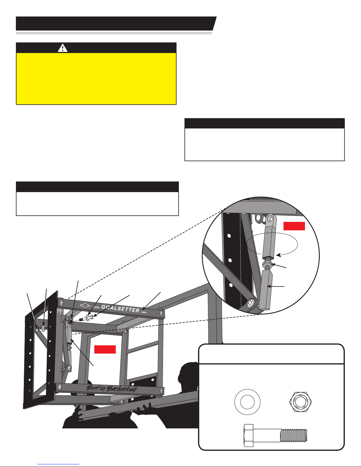
4. Two or three people in good physical condition and capable of
lifting at least 90-100 lbs. (40-45 kg) each are recommended
for safe installation and assembly.
5. Walls can contain electrical wires and other unseen hazards and
obstacles. It is the installer’s responsibility to locate and avoid
these hazards during installation.
• If using a ladder during assembly, use extreme caution. Follow all
warnings and cautions on the ladder carefully.
• Installation and assembly of this product will require lifting and
bending that may result in injury to anyone not accustomed to
this type of activity.
• Ensure there are no overhead power lines within a 20 ft. (7 m)
radius of the goal location.
• Climate, corrosion or misuse could result in system failure.
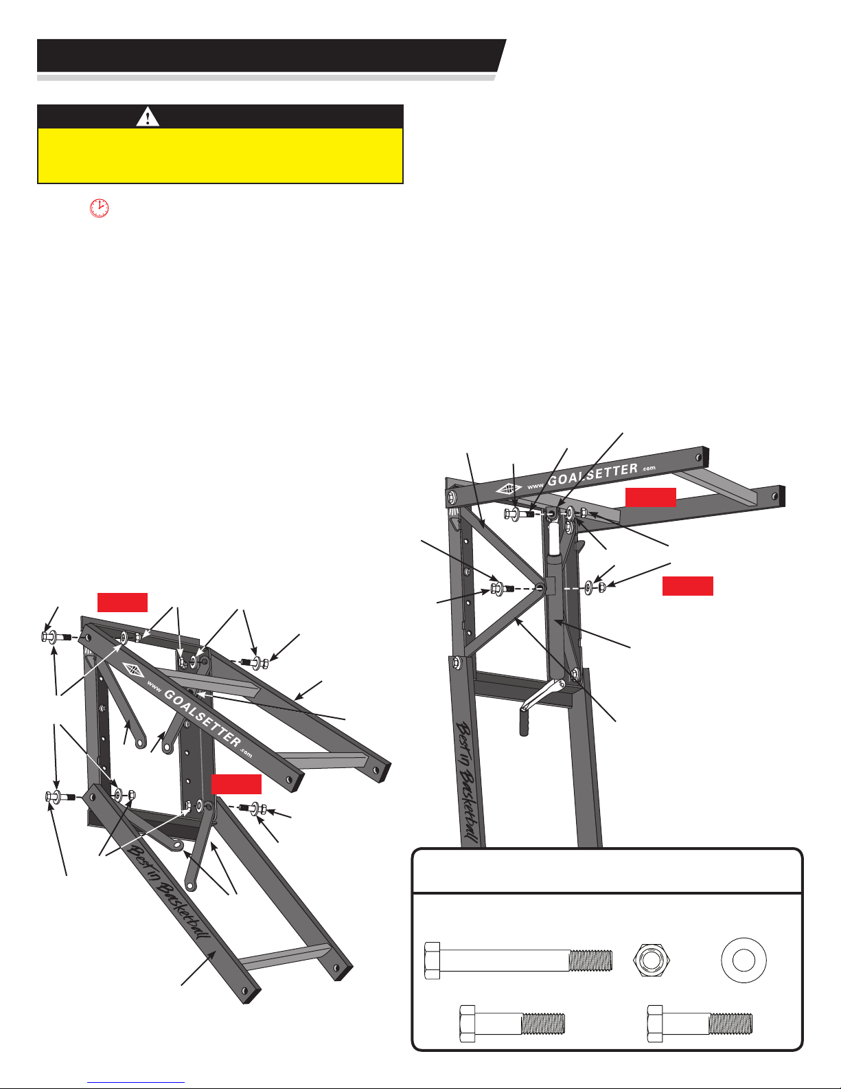
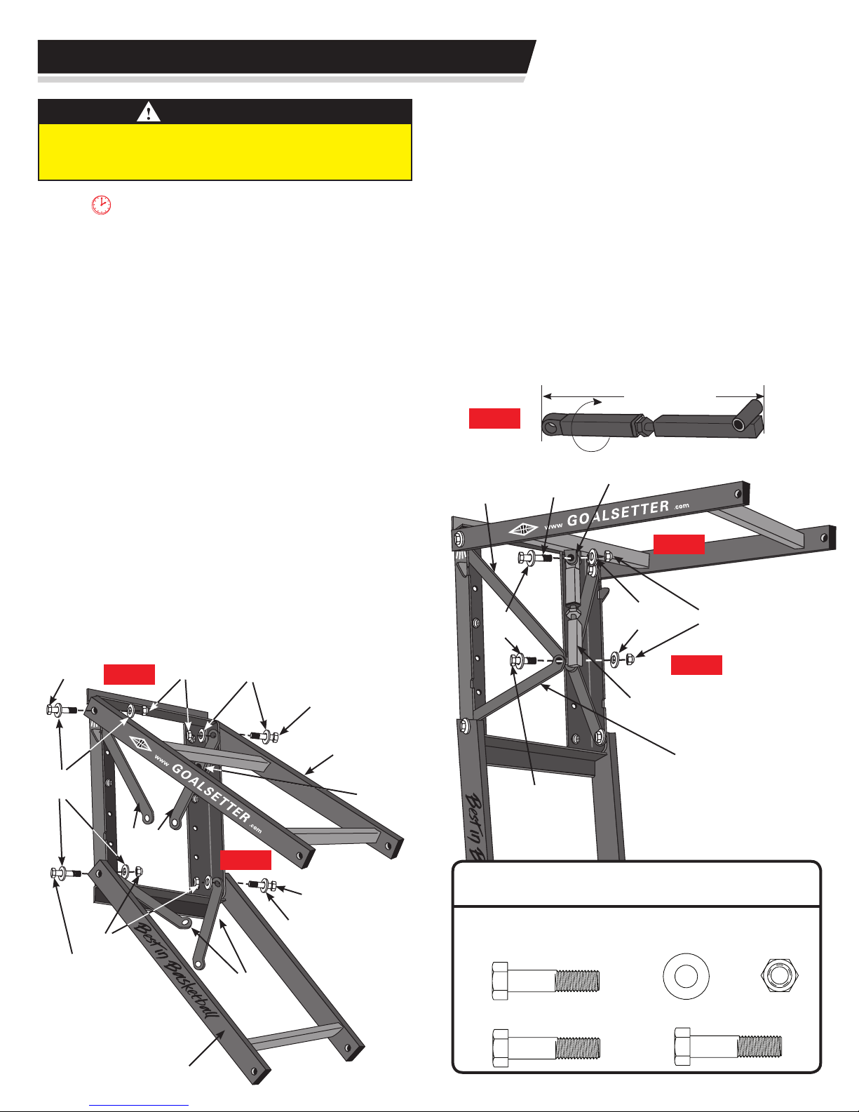
• Only use parts provided with your Goalsetter®basketball goal
system or replacement parts provided by Goalsetter Systems,
Inc. Use of other parts (a) may cause the goal system to fail,
(b) could result in death, serious injury or property damage, and
(c) will void the warranty.
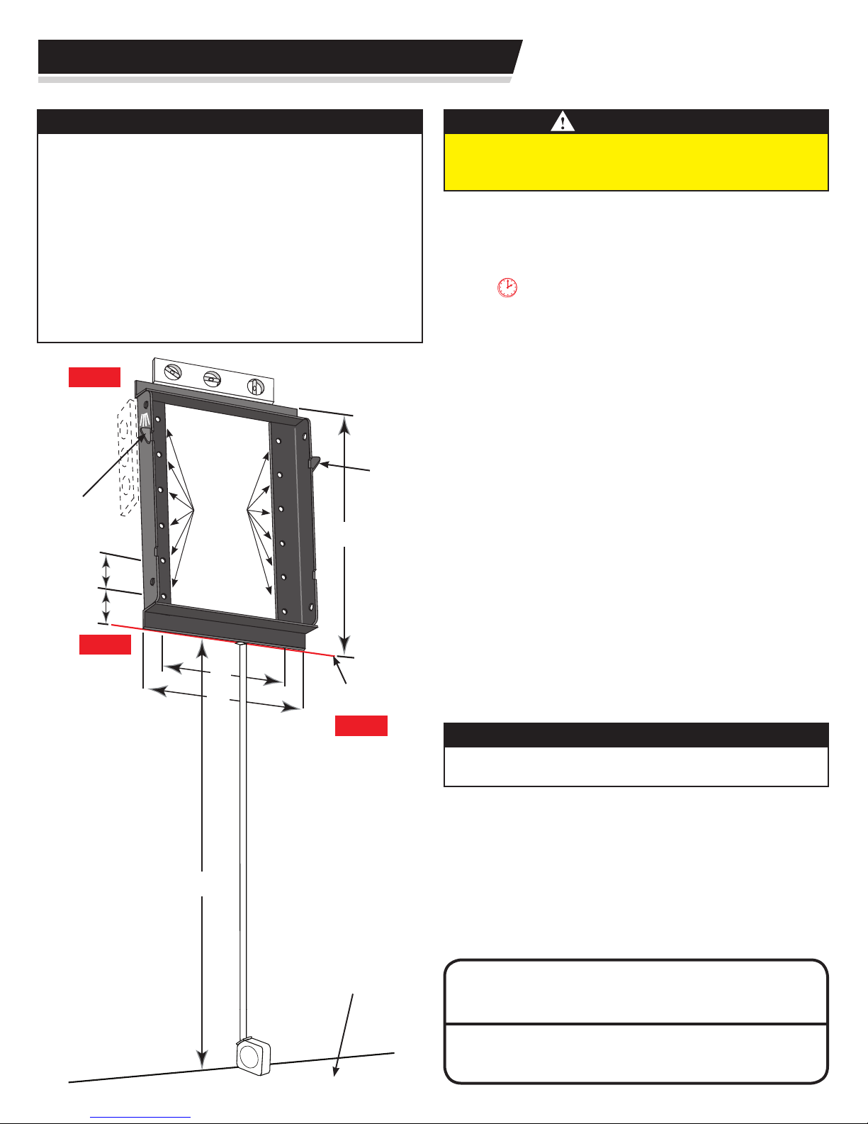
• With rim set at 6’-0” playing height, the minimum operational
height is 5’-4” (1.625 m) to the bottom of the backboard.
• DO NOT CLIMB OR HANG on the rim or any part of the goal
system. This includes the backboard, support braces and net.
The product is not designed for such use and property damage
or personal injuries such as cuts, broken bones, nerve, spinal
cord or brain injury or death could occur.
2
• Use caution when performing dunking activities with this product.
• During play keep players’ faces away from the backboard, rim and
net or serious injury could result.
• Players must wear a mouth guard to avoid dental injuries.
• Do not wear jewelry (rings, watches, necklaces, etc.) or other
loose objects that could become tangled in the net or injure
another player.
•
Before each use, check the goal system for loose hardware, exces-
sive wear and signs of corrosion. Repair the system before use.
• NEVER play on damaged equipment.
•
When adjusting the system height, keep hands and fingers away from
moving parts. DO NOT allow children to adjust the system height.
• Check the goal system frequently for signs of corrosion. Remove
surface rust and loose paint completely, and repaint with exterior
enamel paint. If rust or corrosion has penetrated or pitted any
components of the goal, DO NOT allow play and repair or replace
parts immediately.
• DO NOT use the goal system to lift or hoist anything.
• Use caution when using this goal system. Most injuries are
caused by misuse and/or not following these instructions.
IMPORTANT
Enclosed underneath the protective sheeting on your backboard
is a warranty registration card. YOU MUST FILL OUT AND
MAIL IN THIS CARD IN ORDER TO HAVE A VALID WARRANTY.
You may also fill out a warranty registration online at
www.goalsettersystems.com.
Retain this manual for future reference of operation, maintenance
and parts information.
The information in this manual is based on the latest information
available at the time of publication. Your goal may have product
improvements and options not yet contained in this manual.
Goalsetter Systems, Inc. reserves the right to make changes at any
time without notice or obligation.
Contact the manufacturer if technical assistance is required.
Additional copies of these instructions are available from:
Goalsetter Systems, Inc.
1-800-362-GOAL(4625)
www.goalsettersystems.com

3
Goal Specifications
A
B D
C
J
I
H
F
E
Playing Surface
G
Determine Installation Location
Consider the following to determine where to install your
Goalsetter Basketball Goal:
• The type and strength of structure to which the goal will
be attached.
• When extended, will backboard overhang obstruct driveway or
other important space? Maximum overhang: 69” (1.75 m) from
the mounting surface to the front of the rim.
• Is there room so vehicles backing out of driveway do not strike
backboard or rim?
• Will court markings be used?
• How much playing surface is needed?
• How much playing surface will be under the backboard?
(Having the edge of the playing surface directly underneath the
backboard can result in trip hazards and unpredictable ball action
following a shot. Try to have as much playing surface as possible
behind the backboard.)
• Other functions of playing surface (driveway, playground, etc.)
• Will the goal be at least 20 ft. (7 m) from any overhead power
lines? (No overhead power lines should be within a 20 ft. (7 m)
radius of the goal.)
Required Tools and Materials:
• Level • Phillips Screwdriver
• Rubber Mallet • 9/16”, 3/4” and 15/16” Sockets and Wrenches
• 12’ Tape Measure • Wall Fasteners (not included, provided
• Ratchet by customer or installer)
• Stepladder • Drill and Drill Bits (masonry
if necessary)
• 1 1/8” Wrench
GS72 GS60 GS54
Backboard Size: 42”x72” 38”x60” 36”x54”
Weight w/Acrylic: 225 lbs. 210 lbs. 185 lbs.
Weight w/Glass: 285 lbs. 260 lbs. 225 lbs.
(A) Height Range: 6’-10’ 6’-10’ 6’-10’
(B) Extension Distance:
at 10’ 33” 33” 33”
at 8’ 44” 44” 44”
at 6’ 39” 39” 39”
(C) Maximum Overhang: 69” 69” 69”
(D) Distance Rim to Backboard: 25” 25” 25”
(E) Distance Rim to Top of Goal: 33
3/4
”29
3/4
” 27
3/4
”
(F) Crank Distance:* 5”- 8” 5”- 8” 5”- 8”
(G) Crank Height:* 82” 82” 82”
(H) Height to Bottom of Frame: 88” 88” 88”
(I) Frame Size: 28” 28” 28”
(J) Top of Frame Height: 116” 116” 116”
6'-0"
19'-9"
50'-0" Optimum Inside Sidelines
15'-0"
19'-0"
25'-0"
63"
15"
12'-0"
4'-0"
Note: Lines are 2" wide.
Court Markings
(Reference Only):
Regulation Court Lengths
High School: 84’
College & Professional: 94’
IMPORTANT
Goalsetter Systems, Inc. cannot assume liability for the installation
of any wall-mounted structure. Goalsetter® Systems recommends
consulting a professional architect or contractor to determine a safe
wall anchoring system to match the wall construction being used in
your application.
* Dimensions (F) and (G) do not apply to xed height goals.

4
HARDWARE:
Wall Fasteners (determined and provided by customer and/or installer)
Frame Attachment
IMPORTANT
• Bottom of frame should be 88” up from playing surface. This
is needed to achieve full range of goal height adjustability.
• Wall hanging location is the responsibility of the customer
and/or installer.
• It is the responsibility of the customer and/or installer to
determine how many of the frame’s 12 mounting holes must
be used to safely secure the wall mount goal for play.
• Walls can contain electrical wires and other unseen hazards
and obstacles. It is the installer’s responsibility to locate and
avoid these hazards during installation. To avoid severe injury
or death, do not locate goal under power lines.
WARNING
Two or three people in good physical condition and capable of
lifting at least 90-100 lbs. (40-45 kg) each are recommended for
safe installation and assembly
.
Step 1: Determine where to place frame on mounting
surface. The frame is 28” high x 21” wide. The frame holes are
16” on center.
TIME OUT TIP: Use a level to make drawing
the horizontal line easier.
Step 2: Draw a horizontal line at least 21” (533 mm)
on the mounting surface that is 88” (2.235 m) up from the
playing surface.
Step 3: Unpack the frame. Lay aside extension arms, jack
mounting brackets and jack.
Step 4: Position and center frame bottom on the
horizontal line with the frame’s safety stops at the top.
Step 5: Level frame horizontally and vertically using a
level. Mark the mounting holes needed for attachment of frame.
Step 6: Set frame down.
Step 7: Drill appropriate size holes as needed in
mounting surface based upon type of wall fastener being used
by customer or installer.
Step 8: Loosely attach frame to mounting surface using
correct fasteners.
IMPORTANT
Fasteners to be determined and provided by the customer and/
or installer.
Step 9: Level frame horizontally and vertically using a
level and appropriately tighten fasteners.
TOOLS:
12’TapeMeasure,Level,
Drills and Wrenches (determined by customer and/or installer)
Step2
Step4
Step5
Safety
Stop
Horizontal
Line
Safety
Stop Mounting
Hole
(9/16”)
Playing
Surface
88”
16”
2½”
21”
4”
4”
28”

5
Step 4: Attach upper mount of jack assembly to jack
mount clevis on upper extension arm using the following:
one upper jack pivot bolt, two flat washers, and locknut.
NOTE: DO NOT over-tighten. Snug tighten only.
Step 5: Attach lower mount of jack assembly to
the upper and lower jack mounting brackets using
the following: one lower jack pivot bolt, two at washers, and
locknut. NOTE: DO NOT over-tighten. Snug tighten only.
Step 6: Tighten all extension arm bolts to extension
arms and mounting brackets. Tighten jack pivot bolts, but
make sure free movement is maintained at the pivot points.
Step 7:
Remove protective material from
extension arms.
Frame Assembly
WARNING
Two or three people in good physical condition and capable of
lifting at least 90-100 lbs. (40-45 kg) each are recommended for
safe installation and assembly
.
TIME OUT TIP: The lower extension arm says
“Best in BasketballTM” and the upper extension arm
says “Goalsetter.com”. The lower jack mounting
bracket is shorter (14 ½” (36.83 cm) long).
Step 1: Unpack extension arms and jack mounting
brackets.
Step 2: Making sure decal is right side up, align
lower extension arm holes to outside holes of the
frame ange. Then align holes in lower jack mounting bracket
to inside holes of the frame ange. Connect using the following:
two extension arm bolts, four at washers and two locknuts.
NOTE: DO NOT over-tighten. Snug tighten only.
Step 3: Making sure decal is right side up, attach
the upper extension arms and upper jack mounting
brackets to the frame ange following the same procedure
and hardware as in Step 2.
HARDWARE:
TOOLS:
Rubber Mallet, 15/16” Socket, 15/16” Wrench
5/8 x 21/2” Lower Jack Pivot Bolt (1) 5/8 x 21/2”ExtensionArmBolt(4)
5/8 x 41/2” Upper Jack Pivot Bolt (1) 5/8”Locknut(6) 5/8”FlatWasher(12)
Locknut
Upper Jack
Pivot Bolt
Lower Jack
Pivot Bolt
Jack Mount
Clevis
Step4
Step5
Lower Jack
Mounting
Bracket
Upper Jack
Mounting
Bracket
Flat
Washer
Flat
Washer
Jack
Assembly
Locknut
Locknut
Flat
Washer
Flat
Washer
Flat
Washer
Extension
Arm Bolt
Extension
Arm Bolt
Extension
Arm Bolt
Upper
Extension Arm
Lower
Extension Arm
Lower Jack
Mounting
Bracket
Jack
Mount Clevis
Extension
Arm Bolt Step 3
Step2
Upper Jack
Mounting
Bracket
Adjustable Height Goals Only
Flat
Washer

6
Step 5: Attach upper mount of stabilizer bar to jack
mount clevis on upper extension arm using the following:
one upper jack pivot bolt, two flat washers, and locknut.
NOTE: DO NOT over-tighten. Snug tighten only.
Step 6: Attach the stabilizer bar to the lower jack
mounting bracket using the following: one lower jack pivot bolt,
two flat washers, and locknut. NOTE: DO NOT over-tighten. Snug
tighten only.
Step 7: Tighten all extension arm bolts to extension
arms and mounting brackets. Tighten upper and lower jack
pivot bolts, but make sure free movement is maintained at the
pivot points.
Step 8: Remove protective material from extension arms.
Frame Assembly
WARNING
Two or three people in good physical condition and capable of
lifting at least 90-100 lbs. (40-45 kg) each are recommended for
safe installation and assembly
.
TIME OUT TIP: The lower extension arm says
“Best in BasketballTM” and the upper extension arm
says “Goalsetter.com”. The lower jack mounting
bracket is shorter (14 ½” (36.83 cm) long).
Step 1: Unpack extension arms and jack mounting
brackets.
Step 2: Making sure decal is right side up, align lower
extension arm holes to outside holes of the frame
ange. Then align holes in lower jack mounting bracket to
inside holes of the frame ange. Connect using the following: two
extension arm bolts, four at washers and two locknuts.
NOTE: DO NOT over-tighten. Snug tighten only.
Step 3: Making sure decal is right side up, attach
the upper extension arms and upper jack mounting
brackets to the frame ange following the same procedure
and hardware as in Step 2.
Step 4: Set stabilizer bar length to 21
7/8” (32.70 cm)
by turning the bar to lengthen or shorten. NOTE: After the goal is
raised, further adjustment may be necessary to achieve a 10’ or
desired height.
Step4
21
7/8” (32.70 cm)
Locknut
Locknut
Flat
Washer
Flat
Washer
Flat
Washer
Extension
Arm Bolt
Extension
Arm Bolt
Extension
Arm Bolt
Upper
Extension Arm
Lower
Extension Arm
Lower Jack
Mounting
Bracket
Jack
Mount Clevis
Extension
Arm Bolt Step 3
Step2
Upper Jack
Mounting
Bracket
Locknut
Flat
Washer
Flat
Washer
Upper Jack
Pivot Bolt
Stabilzer
Bar
Lower Jack
Pivot Bolt
Jack Mount
Clevis
Step6
Step5
Lower Jack
Mounting
Bracket
Upper Jack
Mounting
Bracket
HARDWARE:
TOOLS:
Rubber Mallet, 15/16” Socket, 15/16” Wrench
5/8 x 21/2”ExtensionArmBolt(4)
5/8 x 21/2” Upper Jack Pivot Bolt (1)
5/8”Locknut(6)
5/8”FlatWasher(12)
5/8 x 21/2” Lower Jack Pivot Bolt (1)
Fixed Height Goals Only

810
Flat
Washer
Flat
Washer
Backboard
Bolt
Backboard
Bolt
Backboard
Bolt Locknut
Step2
Step 3
Rim Mounting
Plate
WARNING
Backboards can weigh between 168 lbs. to 266 lbs.
Two or
three people in good physical condition and capable of lifting
at least 90-100 lbs. (40-45 kg) each are recommended for safe
installation and assembly
.
IMPORTANT
Extension arms MUST be in the lowered position.
TIME OUT TIP: Lay the unopened box with
Goalsetter® logo upside down AND let the lid open
up and fold away from the goal mounting surface.
Step 1: Open lid of box containing the backboard and
slide the backboard face down, with rim mounting plate facing
towards the goal mounting surface.
Backboard Attachment
Step 2: Carefully lift the backboard from the box and
align upper backboard holes with upper extension arm
holes using the following software: two backboard bolts, four
flat washers, and two locknuts. NOTE: This is a pivot point! DO
NOT over-tighten. Snug tighten, so that bushings in arms meet
bushings in backboard.
TIME OUT TIP: Extension arms attach to the
outside of backboard’s H-frame.
Step 3: Align lower backboard holes with the lower
extension arm holes using the same procedure and hardware
as in Step 2.
1/2” Locknut(4)
1/2x 21/2”
BackboardBolt(4) 1/2” Flat Washer (8)
HARDWARE:
TOOLS:
Rubber Mallet, 3/4” Socket, 3/4” Wrench
7

Step 3
Step4
Flat
Washer Factory Installed Bushing
(Backboard damage can result if not installed)
Flat
Washer
Flat
Washer
Backboard
Bolt
Backboard
Bolt
Lock
Washer Nut
8
Rim Attachment
NOTE: Use all steps of the following instructions to install a reex
rim. To install a static rim, follow all steps except Steps 2 and 6.
TIME OUT TIP: Your warranty card is located
behind protective sheeting. You MUST fill out and return
this card to activate your warranty.
Step 1: Unpack rim. Remove any remaining cardboard edge
protectors and protective sheeting from backboard.
IMPORTANT
• Four bushings are factory installed on the backboard. If loose,
make sure to have them seated properly when tightening rim
bolts. If missing, contact Goalsetter or dealer.
DO NOT install rim without bushings. If the bushings are
not in place, glass backboards can shatter and acrylic
backboards can crack!
• Correct sequence of hardware installation MUST be followed
during assembly.
Step 2: If not already removed, remove cover plate
screws and cover plate from rim assembly.
Step 3: Starting with the top two mounting holes,
loosely attach rim to backboard following the
hardware sequence as shown in the illustration below.
Snug tighten hardware.
Step 4: Repeat hardware sequence outlined in Step 3
for lower rim mounting holes.
Step 5: Level rim side to side and then fully tighten
hardware.
Step 6: Position cover plate and attach with cover
plate screws.
Step 7: Attach net to rim.
3/8 x 2”
BackboardBolt(4) 3/8” Flat Washer (8) 3/8” LockWasher(4) 3/8” Nut(4)
Cover Plate
Screw(4)
TIME OUT TIP: Level rim side to
side before tightening backboard bolts.
HARDWARE:
TOOLS:
Level, 9/16” Wrench, 9/16” Socket, Phillips Screwdriver
Step6
Cover Plate
Screw
Cover Plate
Screw
Cover
Plate

810
Step 3
Step4
Flat
Washer Flat
Washer
Stabilizer
Bar
Locknut
9
Raise and Adjust Backboard
WARNING!
To prevent serious injury or death, if using a stepladder, make
sure it is in good condition, setting on a level and stable surface
and do not exceed its weight rating.
Use two or three people to raise backboard assembly and hold
it at the 10’ position. They should be in good physical condition
and capable of lifting at least 90-100 lbs (40-45 kg) each.
Step 1: Measure the distance from the playing surface
to top of rim with a tape measure.
Step 2: Subtract the measured distance from 10’ – this
is the amount the goal will need to be adjusted.
Step 3: While one or two people hold up backboard,
remove the upper jack pivot bolt, washers and locknut
from the jack mount clevis on upper extension arm.
IMPORTANT
DO NOT over-extend threaded rod in stabilizer bar. If total length
needed is over 22
½”
(57.15 cm), DO NOT USE. Call Goalsetter
or your local dealer for a custom-length stabilizer bar.
Step 4: Lengthen or shorten the stabilizer bar
by
turning it ½ turn for every ¼” of adjustment needed (or 1 full turn
for every ½” adjustment needed).
Step 5: Re-attach stabilizer bar to the jack mount
clevis on upper extension arm
using the hardware removed
in Step 3.
Step 6: Repeat steps 1-5 until a rim height of 10’
is achieved.
IMPORTANT
After all height adjustments have been completed, make sure
all hardware is properly tightened, including stabilizer bar
locking nut. Nut should be tightened toward the top of threaded
rod, against top stabilizer bar section using a 11/8” wrench.
HARDWARE:
Removed and Reattached
TOOLS:
Stepladder,12’TapeMeasure,3/4” Socket, 15/16” Wrench, 1 1/8” Wrench
5/8 x 2
1/2” Upper Jack Pivot Bolt (1)
5/8”Locknut (1)
5/8”FlatWasher(2)
Stabilizer
Bar
Upper Jack
Pivot Bolt
Jack Mount
Clevis
Stabilizer Bar
Locking Nut
Upper
Extension Arm
Fixed Height Goals Only

Step 3
Step2
Step 1
10
Step 1: Position top of rim 10’ above playing surface by
turning crank handle.
Step 2: Measure distance with a tape measure for accuracy.
Step 3: Align height indicator bar decal with 10’ mark on
frame and attach to bottom of upper extension arm.
Height Indicator Attachment
TOOLS:
12’TapeMeasure
DECAL:
10’
Adjustable Height Goals Only

11
Goal Assembly, cont.
Operation
Crank handle turns
clockwise for goal to go up,
crank handle turns counter
clockwise for goal to go down.
Height indicator indicates
goal height from 6’ to 10’.
Maintenance
The life of your basketball goal system depends on many
variables. The climate, exposure to corrosives such as salt,
organic materials, pesticides, or herbicides, and excessive use
or misuse can all contribute to failure of the goal system, which
may cause property damage or personal injury. Before each
use, check the goal system for loose hardware, excessive wear,
abuse, or vandalism or signs of rust or corrosion.
For safety reasons, and to prolong the life of your basketball
system, you must take the following preventative measures:
• Check all nuts and bolts. Inspect the threads and replace if
necessary. If any are loose, tighten them.
• Check all parts for excessive wear and tear. If necessary,
replace any parts that have been worn or damaged through
usage.
• Check all sections of the goal system for visible rust or
chipped or cracked paint, and if present, repair appropriately.
See Paint Touch-Up on this page.
IF RUST OR CORROSION HAS PENETRATED ANY
COMPONENT, DO NOT ALLOW PLAY ON THE GOAL AND
REPLACE PARTS IMMEDIATELY.
• Contact Goalsetter Systems, Inc. for replacement parts. Only
use parts provided by Goalsetter Systems, Inc. Use of other
parts (a) may cause the goal system to fail, (b) could result
in death, serious injury or property damage, and (c) will void
the warranty.
• Inspect the Warning Sticker on the pole. If it is ripped, faded
or illegible, contact Goalsetter Systems, Inc. to request a
replacement Warning Sticker.
Cleaning
The exterior nish of your Goalsetter®goal is designed for
outdoor environments and should only require periodic cleaning
and inspection for imperfections that could develop over time.
When cleaning is necessary, Goalsetter recommends using water
and a mild dish detergent applied with a soft, non-abrasive cloth.
IMPORTANT
DO NOT use abrasive cleaners to clean the goal. Damage to the
finish may result.
Paint Touch-Up
Goalsetter Systems, Inc. uses a two-part acrylic-
enamel paint on the goals. With periodic inspection
and service when needed, the high-gloss finish is
designed to last for many years. A small bottle of
black paint with brush is provided in the hardware
kit for touch up of imperfections as they develop. If
more touch up is required, please contact Goalsetter
Systems, Inc. or your local Goalsetter Dealer.
Lubrication
The jack is pre-lubricated. As with any mechanical component,
periodic inspection and service is required. Goalsetter Systems,
Inc. recommends applying lubrication each spring and fall to keep
a smooth operation of the height actuator. Failure to do so could
result in jack failure and not be covered under warranty.
Lubricate jack. Add a liberal amount of lubricating oil to the oil
hole located at end of jack extension arm.
IMPORTANT
A general-purpose lubricating oil like “3-in-1” or lightweight
motor oil is recommended. DO NOT use a penetrating oil (i.e.
WD40.) Goalsetter has “Maintenance Kits” available which
would include a bottle of lubricating oil. Contact Goalsetter
Systems, Inc. or your local Goalsetter Dealer for details.
Black Touch-Up Paint
Ready to Play
Rubber
Boot
Drain
Hole
Oil
Hole

12
Warranties
IMPORTANT
Enclosed underneath the protective sheeting on your backboard
is a warranty registration card. YOU MUST FILL OUT AND
MAIL IN THIS CARD IN ORDER TO HAVE A VALID WARRANTY.
You may also fill out a warranty registration online at
www.goalsettersystems.com.
LIMITED WARRANTY
LIMITED LIFETIME WARRANTY: Subject to proper installation and normal, intended use, and subject to the
limitations set forth below, Goalsetter Systems, Inc. warrants to the original retail purchaser that all structural
components of Goalsetter® Systems Signature Series*, Extreme Series** and GS Wall-Mount Series*** basketball
systems are free of defects in material and workmanship for the duration of ownership by such original retail
purchaser or 5 years after discontinuation of the product by Goalsetter Systems, Inc..
*Signature Series – MVP, Captain, All-American, All-Star, Contender, Champion;
**Extreme Series – X672, X660, X560, X554, X454, X448;
***GS Wall-Mount Series – GS72 Wall-Mount, GS60 Wall-Mount, GS54 Wall-Mount, GS48 Wall-Mount; Tournament
Series – Elite, Classic; GS Portable Series – GS1000, GS2000, GS2500, GS3000, GS3500.
LIMITED WARRANTY: Subject to proper installation and normal, intended use, and subject to the limitations set
forth below, Goalsetter Systems, Inc. warrants to the original retail purchaser that all structural components of (a)
Goalsetter Systems Tournament Series* basketball systems are free of defects in material and workmanship for a
period of ve years from date of purchase (b) Goalsetter Systems GS Portable Series* basketball systems are free of
defects in material and workmanship for a period of two years from date of purchase.
Any warranty on a basketball system excludes the rim. Rim warranties are as follows: Rims shall be free from
defects in materials and workmanship from the date of purchase as follows: Single Ring Static Rim: two-year limited
warranty; Double Ring Static Rim: limited lifetime Warranty; Home Court Flex Rim: one-year limited warranty; Heavy
Duty Flex Rim: two-year limited warranty; GS Ultra Flex Rim: ve-year limited warranty; GS Collegiate Breakaway
Rim: ve-year limited warranty; Double Ring Static Galvanized Rim: limited lifetime warranty.
Padding Warranty: Padding shall be free from defects in materials and workmanship from the date of purchase
as follows: Multi-Purpose Backboard Edge Padding: one-year limited warranty; Indoor Backboard Edge Padding:
ve-year limited warranty (indoor only); Custom Fitted Pole Padding: one-year limited warranty; Wrap Around Pole
Padding: one-year limited warranty
MISC PRODUCT WARRANTIES: The following products shall be free from defects in materials and workmanship
from the date of purchase as follows:
Other Portable Systems: GS1000 – 2 year limited warranty; GS4500: 5-year limited warranty; GS5000: Base, 10-
year limited warranty; Pole, Backboard, Hand Crank, Padding and Rim, 5-year limited warranty; GS6000 & GS7000:
Portable structure, 10-year limited warranty; Backboard, limited lifetime warranty; Padding and Rim, 5-year limited
warranty
Playground Structures: All GS MAX & GS Double MAX Systems: 10-year limited lifetime warranty; RP775 3-1/2”
Gooseneck Pole: 10-year limited warranty; RP776 3-1/2” Adjustable Pole: 10-year limited warranty; RP777 4-1/2”
Gooseneck Pole: 25-year limited warranty; RP778 4-1/2” Adjustable Pole: 25-year limited warranty; RP780 Mega
Duty Pole: limited lifetime warranty
Gym Structures & Accessories: Stationary, Side Fold and Swing Up Wall Mounted Structures: limited lifetime
warranty; Height Adjuster: 10-year limited warranty; A11067 Wall Mount Power Winch: 5-year limited warranty;
A11068 Portable 110 Volt Winch: 1-year limited warranty; A11008 Fail-Safe Structure Catch: 10-year limited
warranty; A11200 Easy-Up Youth Mini Goal: 1-year limited warranty on structure and rim, limited lifetime warranty
on backboard
Rims & Nets: R10126 Single Ring Static: 2-year limited warranty; R10226 Double Ring Static: limited lifetime
warranty; R10326 Heavy Duty Reex: 2-year limited warranty; R10426 GS Ultra Flex: 5-year limited warranty;
R10554 GS Collegiate Breakaway: 5-year limited warranty; R10654 GS Pro Breakaway: 5-year limited warranty;
R10834 Home Court Reex: 1-year limited warranty; R10935 GS Premier Breakaway: 5-year limited warranty;
A11013 Steel Net: 2-year limited warranty
Institutional Backboards: CB4272RG 42x72 Competition Glass: limited lifetime warranty (indoor only);
CB4272RGCV 42x72 Competition Glass Conversion: limited lifetime warranty (indoor only); CB4872RG 48x72
Rectangular Glass: 20-year limited warranty (indoor only); RB4254GC 42x54 Glass Conversion: limited lifetime
warranty (indoor only); CB3954FG Fan-Shaped Glass: limited lifetime warranty (indoor only); RB4260RS 42x60
Rectangular Steel: 10-year limited warranty; RB3954RS 39x54 Rectangular Steel: 10-year limited warranty;
RB3954FS 39x54 Fan Steel: 10-year limited warranty; RB3954RA 39x54 Rectangular White Aluminum: limited
lifetime warranty on direct mount pole systems; RB3654FCA 36x54 Fan Cast Aluminum: limited lifetime warranty
on direct mount pole systems, otherwise 10-year limited warranty; RB3654FA 36x54 Fan White Aluminum: limited
lifetime warranty on direct mount pole systems, otherwise 10-year limited warranty; RB4272RF 42x72 Rectangular
Fiberglass: 10-year limited warranty; RB4254RP 42x54 Rectangular Polycarbonate: limited lifetime warranty;
RB4254RG 42x54 Rectangular Glass: limited lifetime warranty; RB3954FP 39x54 Fan Polyethylene: limited lifetime
warranty
The Limited Lifetime Warranty and the Limited Warranty shall cover damage or failure that occurs during the
course of NORMAL or INTENDED USE of the product. Normal or intended use shall be described as activity that is
necessary for the participation in the sport for which the equipment is designed. NOT COVERED is damage caused
by deliberate hanging, multiple player hanging, vandalism, non-basketball activities or any other activity that could
be regarded as abusive.
A limited lifetime warranty is effective for the duration of ownership by the original retail purchaser or 5 years after
discontinuation of the product by Goalsetter Systems, Inc.
Goalsetter Systems, Inc. shall have the right to require the purchaser to deliver at its expense the allegedly
defective product to Goalsetter for testing, repair or replacement. Goalsetter shall not be responsible for any
expenses associated with the replacement or removal of the product from its application for such delivery.
THE WARRANTY IS VOID IF THE PRODUCT HAS BEEN DAMAGED BY ACCIDENT, USE FOR PURPOSES
FOR WHICH IT IS NOT INTENDED, AS THE RESULT OF IMPROPER INSTALLATION, FAILURE TO FOLLOW
INSTALLATION, CARE OR MAINTENANCE INSTRUCTIONS PROVIDED WITH THE PRODUCT, USE OF PARTS
NOT PROVIDED BY GOALSETTER SYSTEMS OR ANY MODIFICATION OF ANY PRODUCT BY THE CUSTOMER
UNLESS APPROVED BY GOALSETTER SYSTEMS, INC., OR OTHER CAUSES NOT ARISING OUT OF DEFECTS IN
MATERIALS OR WORKMANSHIP,
The sole obligation of Goalsetter Systems, Inc., and the exclusive remedy under the applicable warranty, is repair
or replacement of any component part determined by Goalsetter Systems, Inc. to be defective and covered by the
warranty. Goalsetter Systems, Inc. will not be liable for any other damages or expenses. The applicable warranty
is expressly in lieu of all other warranties, express or implied. Goalsetter Systems, Inc. does not assume, and no
other person or representative is authorized to assume for Goalsetter Systems, Inc. any other liability in connection
with the sale of Goalsetter System products.
NOT COVERED BY WARRANTY
• Use in non-residential applications of Glass backboards on Signature Series systems.
• Use in non-residential applications of Extreme Series and Tournament Series complete systems.
• Any products subjected to abuse, negligence, improper installation, vandalism, acts of God, alteration of product
and any other events beyond the control of Goalsetter Systems, Inc.
• Paint or rusted parts. Touch-up paint is included in all hardware kits.
• Deterioration of product due to time or wear and tear.
Normal deterioration of products due to atmospheric conditions, weather, wear and tear (including scratching or
scufng paint from normal use), or other causes that do not affect functional use are not covered by Goalsetter
Systems, Inc. warranties. All warranties are valid only when product is used in the intended application & when
installed according to Goalsetter Systems instructions. Warranty may be void if maintenance instructions in the
Owner’s Manual are not followed. If you did not receive an Owners Manual, please call 1-800-362-4625 and one
will be mailed to you.
DISCLAIMERS: THE APPLICABLE WARRANTY IS EXPRESSLY IN LIEU OF ALL OTHER WARRANTIES, EXPRESS
OR IMPLIED. AND ALL OTHER WARRANITES ARE HEREBY DISCLAIMED, INCLUDING BUT NOT LIMITED TO
THE IMPLIED WARRANTIES OF MERCHANTABILITY AND FITNESS FOR A PARTICULAR PURPOSE. UNDER
NO CIRCUMSTANCES SHALL GOALSETTER SYSTEMS, INC. BE LIABLE FOR ANY INDIRECT, CONSEQUENTIAL,
SPECIAL, INCIDENTAL, PUNITIVE, OR EXEMPLARY DAMAGES OF ANY KIND.
THE PRODUCT IS INTENDED TO BE USED TO PLAY THE SPORT OF BASKETBALL. ALL SPORTS INVOLVE RISK
OF INJURY. THE USER ASSUMES ALL RISK OF INJURY RESULTING FROM THE USE OF THIS PRODUCT. ALL
PRODUCTS ARE SOLD ON THIS CONDITION AND NO REPRESENTATIVE OF THE COMPANY MAY WAIVE OR
CHANGE THIS POLICY.
Some states do not allow the exclusion or limitation of implied warranties or consequential or incidental damages,
so the above limitations or exclusions may not apply to you.
LEGAL REMEDIES: This warranty gives you specific legal rights, and you may also have other rights which may
vary from state to state.
WARRANTY CLAIMS: All returns must be arranged through the Goalsetter Systems, Inc. dealer where the product
was originally purchased. Warranties do not cover dealer service charges, labor charges, freight charges, and travel
expenses associated with replacement, repair or removal of warranty items. A Goalsetter Warranty Claim form
must be completed, and photos submitted, together with proof of purchase, for any item you wish to claim under
warranty. If the purchase was not made through a dealer, this form is available by email, fax or mail. In response
to your claim, you will receive an order conrmation as well as a notice stating whether Goalsetter Systems, Inc.
needs your warranty item returned. Goalsetter Systems, Inc. will notify you by fax or phone if we determine that the
item cannot be claimed under warranty. Goalsetter Systems, Inc. is not responsible for any charges for labor to
install or repair defective product without prior authorization. Goalsetter Systems, Inc. will determine the most
economical method to either repair or replace product before any work is to commence.
Questions or Comments?
Phone800.362.4625
Fax:641.594.3343
Email:[email protected]
www.goalsettersystems.com
GOALSETTER and GOALSETTER BASKETBALL logo are registered trademarks of Goalsetter Systems, Inc. in the
United States. GOALSETTER SYSTEMS and BEST IN BASKETBALL are trademarks of Goalsetter Systems, Inc.
This product is covered by various U.S. and Canadian patents, including U.S. Patent #5,211,393. Patent
infringement will be prosecuted.
No part of this manual may be reproduced in any form or by any means electronic or mechanical, including
photocopying, recording, or by any information storage and retrieval systems without the express written consent
of Goalsetter Systems, Inc.
Copyright 2006.
All rights reserved.
Revised 1/2011
Goalsetter Systems, Inc.
This manual suits for next models
3
Table of contents
Other Goalsetter Systems Accessories manuals