1. As a Wireless Studio Flash Trigger
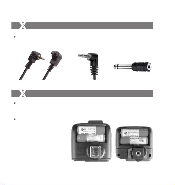
1.1 Mount the transmitter on camera hotshoe and turn it
on before turning on the camera.
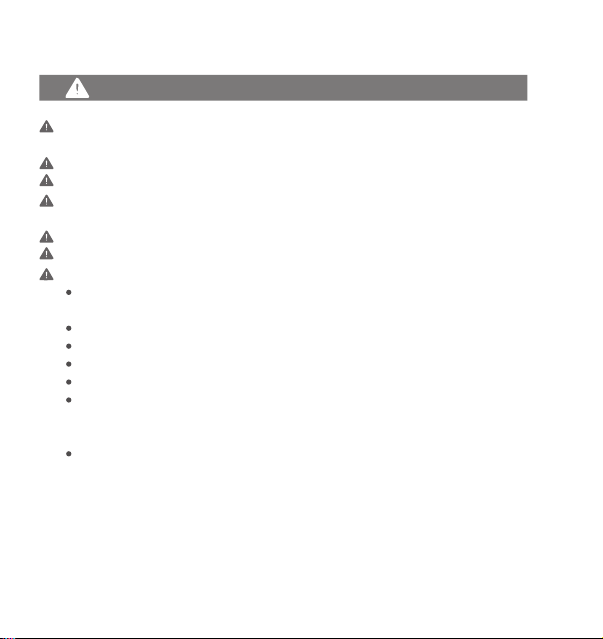
1.2 Connect the receiver to studio flash by Sync Cable
(one end in 2.5mm Shutter Release Port of the
receiver, the other end in sync port of studio flash)
before turning on the studio flash.
1.3 Set the transmitter and the receiver to the same
channel.
1.4 Press the camera shutter button, and the studio
flash will be triggered simultaneously. Status
Indicator Lamp of both transmitter and receiver
units turn red.
The flash trigger features the following functions:
Using the Flash Trigger
2. As a Wireless Speedlite Trigger
2.1 Mount the transmitter on camera hotshoe and turn it
on before turning on the camera.
2.2 Mount the speedlite to Hot Shoe Speedlite
Connection of receiver unit. Set the speedlite to M
mode.
2.3 Set the transmitter and the receiver units to the
same channel.
2.4 Press the camera shutter button, and the speedlite
will be triggered simultaneously. Status Indicator
Lamp of both transmitter and receiver units turn red.
- 31 - - 32 -
3. As a Wired Shutter Release
3.1 Connect the receiver and the camera by Remote
Cable (one end in receiver’s Shutter Release
Port, the other end in camera’s shutter port)
before turning on the camera.
3.2 Half press the <TEST> Trigger Button to focus.
When fully press the <TEST> Trigger Button to
shoot, the Status Indicator Lamp will turn red until
releasing the button.
Using the Flash Trigger
4. As a Wireless Studio Flash Trigger or Speedlite
Trigger with PC Sync Socket
4.1 The connection method of the receiver can be
found in As a Wireless Studio Flash Trigger and As
a Wireless Speedlite Trigger section.
4.2 The transmitter will control the flash on the
receiver end to fire via using PC Sync Socket as
input by default.
4.3 Press the camera shutter and use the PC Sync
Socket’s signal to control the flash.
4.4 PC Sync Socket can also be set as output. Long
press the <CH/OK> Button of the transmitter until
<Fn> is displayed on the panel. Then, set the
value of C.Fn-03 to ou, and the PC Sync Socket is
under output mode.