1.2 Long press the <Zm/CH> button to set
channel, group, mode and parameters (refers
to the contents of “Setting the Flash Trigger”).
1.3 Turn on the camera flash, press the
wireless setting button and the wireless
icon and <SLAVE> slave unit icon will be
displayed on the LCD panel. Press the <CH>
button to set the same channel to the flash
trigger, and press the <Gr> button to set the
same group to the flash trigger (Note: please refer to the relevant instruction manual when
setting the camera flashes of other models).
1.4 Press the camera shutter to trigger and the status lamp of the flash trigger
turns red synchronously.
Using the Flash Trigger
2.1 Turn off the camera and mount the
transmitter on camera hotshoe. Then,
power on the flash trigger and the
camera.
2. As a Wireless Outdoor Flash Trigger
2.2 Long press the <Zm/CH> button to set
channel, group, mode and parameters
(refers to the contents of “Setting the
Flash Trigger”).
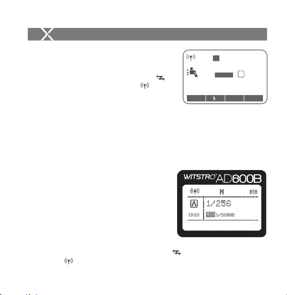
2.3 Power on the outdoor flash and press the wireless setting button and the
wireless icon will be displayed on the LCD panel. Long press the
Take AD600B as an example:
Using the Flash Trigger
3.4 Press the camera shutter to trigger. And the
status lamp of the camera flash and the flash
trigger both turn red synchronously.
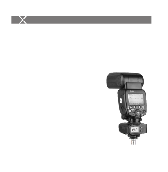
Take 600EX-RT as an example:
3.3 Attach the original flash to the X1R-C receiver.
Press the <CH> button on the receiver to set
the same channel to the flash trigger, and press
the <Gr> button to set the same group to the
flash trigger (Note: please refer to the relevant
instruction manual when setting the original
camera flashes).
3.2 Long press the <Zm/CH> button to set channel,
group, mode and parameters (refers to the
contents of “Setting the Flash Trigger”).
3. As a Wireless Original Flash Trigger
3.1 Turn off the camera and mount the transmitter
on camera hotshoe. Then, power on the flash
trigger and the camera.
GR
CH
- 30 -- 29 -
< >
< >
< >
< >
<GR/CH> button to set the same channel to the flash trigger, and short press
the < GR/CH> button to set the same group to the flash trigger (Note: please
refer to the relevant instruction manual when setting the oudoor flashes of other
models).
2.4 Press the camera shutter to trigger and the status lamp of the flash trigger turns
red synchronously.
M
A
CH19
1/128
Zoom 24
mm
SLAVE
Zm/C.Fn Gr CH
±
M