- 31 - - 32 -
Setting the Transmitter
[Note 1]
Min. refers to the minimum power output value that can be set in M/Multi mode. 1/128 or 1/256 can be
set according to C.Fn-05.
The minimum power output value is 1/128 and cannot be set to 1/256 for most of camera flashes.
However, the value can change to 1/256 when using in combination with Godox strong power flashes
e.g. AD600, etc.
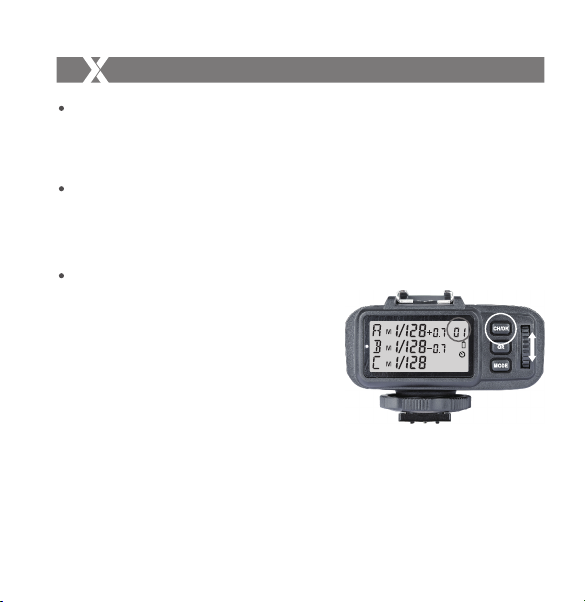
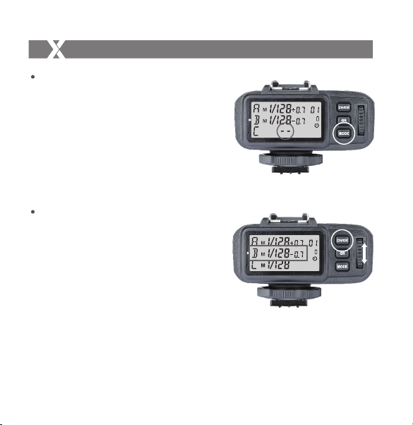
Multi Flash Group ON/OFF Settings
1. Open the multi flash in the C.Fn Custom
Functions (set C.Fn-04 as 1).
2. Short press the <GR> button to select the
group. Click to choose downwardly and
double-click to choose upwardly.
3. Short press the <MODE> Button to change
the mode of selected group.
4. The current group’s mode will be changed by
the order of on/-- (-- represents OFF, which
means that the current group will not fire
flashes in this mode).
Setting the Transmitter
Multi Flash Parameter Setting
1. Enter into multi flash mode before setting.
2. Press the <MODE> Button to enter multi flash
parameter setting menu.
3. Then, P (output value), T (flash times) and H
(flash frequency) will be displayed on the LCD
panel.
4. Short press the <GR> Button to choose the
settings. Turn the Select Dial to change the
blinking setting amount. Continue to press the
<GR> Button until all the amounts are set. Then,
short press the <MODE> Button to exit.
Note: As flash times are restricted by flash output value and flash frequency, it might get
automatic adjustment.
The times that transported to the receiver end are setting times,which is not related to the
camera's shutter setting.
To guarantee the normal times of stroboscopic rimes,please use the formula below to
calculate the shutter speed.
Number of Flashes/Firing Frequency=Shutter Speed.
Group Settings
1. Long press the <GR> Button to set all the groups that in the same modes
simultaneously.
2. The settings of the groups which are in the same mode with the current group will
blink. Turn the Select Dial to change the settings.
3. If the current group is in the M mode, all the other groups which are in the M mode will
change their power output value simultaneously. The power output value is
changeable from 1/1 full power to Min. power in 0.3 stop increments, until one of the