GOK Caramatic DriveOne User instructions

Originalanleitung / Artikel-Nr. 71 813 50 Ausgabe 07.2021
Montage- und Bedienungsanleitung
Caramatic DriveOne
Sicherheits-Gasdruck-Regelanlage für Gastanks
zum Betrieb von flüssiggasbetriebenen Gasgeräten
im Caravan und Motorcaravan während der Fahrt
INHALTSVERZEICHNIS
ZU DIESER ANLEITUNG..........................................................................................................................1
SICHERHEITSBEZOGENE HINWEISE ....................................................................................................2
TECHNISCHE ÄNDERUNGEN.................................................................................................................2
ALLGEMEINE PRODUKTINFORMATION ................................................................................................2
BESTIMMUNGSGEMÄSSE VERWENDUNG ...........................................................................................3
NICHT BESTIMMUNGSGEMÄSSE VERWENDUNG................................................................................4
QUALIFIKATION DER ANWENDER.........................................................................................................4
AUFBAU ...................................................................................................................................................4
ANSCHLÜSSE..........................................................................................................................................4
VORTEILE UND AUSSTATTUNG.............................................................................................................5
FUNKTIONSBESCHREIBUNG .................................................................................................................5
MONTAGE................................................................................................................................................6
DICHTHEITSKONTROLLE .......................................................................................................................7
BEDIENUNG.............................................................................................................................................7
INBETRIEBNAHME ..................................................................................................................................8
FEHLERBEHEBUNG ................................................................................................................................8
AUSSERBETRIEBNAHME .......................................................................................................................8
INSTANDSETZUNG .................................................................................................................................8
WARTUNG ...............................................................................................................................................8
AUSTAUSCH............................................................................................................................................9
LISTE DER ZUBEHÖRTEILE....................................................................................................................9
TECHNISCHE DATEN..............................................................................................................................9
ENTSORGEN ...........................................................................................................................................9
GEWÄHRLEISTUNG ................................................................................................................................9
ZERTIFIKATE ...........................................................................................................................................9
ZU DIESER ANLEITUNG
•
Diese Anleitung ist ein Teil des Produktes.
•Für den bestimmungsgemäßen Betrieb und zur Einhaltung der Gewährleistung
ist diese Anleitung zu beachten und dem Betreiber auszuhändigen.
•Während der gesamten Benutzung aufbewahren.
•Zusätzlich zu dieser Anleitung sind die nationalen Vorschriften, Gesetze und
Installationsrichtlinien zu beachten.
•Diese Anleitung im Fahrzeug aufbewahren!

Caramatic DriveOne
2 / 36 Artikel-Nr. 71 813 50
SICHERHEITSBEZOGENE HINWEISE
Ihre Sicherheit und die Sicherheit anderer ist uns sehr wichtig. Wir haben viele wichtige
Sicherheitshinweise in dieser Montage- und Bedienungsanleitung zur Verfügung gestellt.
Lesen und beachten Sie alle Sicherheitshinweise sowie Hinweise.
Dies ist das Warnsymbol. Dieses Symbol warnt vor möglichen Gefahren, die den
Tod oder Verletzungen für Sie und andere zur Folge haben können. Alle
Sicherheitshinweise folgen dem Warnsymbol, auf dieses folgt entweder das Wort
„GEFAHR", „WARNUNG" oder „VORSICHT". Diese Worte bedeuten:
bezeichnet eine Personengefährdung mit einem hohen Risikograd.
Hat Tod oder eine schwere Verletzung zur Folge.
bezeichnet eine Personengefährdung mit einem mittleren Risikograd.
Hat Tod oder eine schwere Verletzung zur Folge.
bezeichnet eine Personengefährdung mit einem niedrigen Risikograd.
Hat eine geringfügige oder mäßige Verletzung zur Folge.
bezeichnet einen Sachschaden.
Hat eine Beeinflussung auf den laufenden Betrieb.
bezeichnet eine Information
bezeichnet eine Handlungsaufforderung
TECHNISCHE ÄNDERUNGEN
Alle Angaben in dieser Montage- und Bedienungsanleitung sind die Ergebnisse der
Produktprüfung und entsprechen dem derzeitigen Kenntnisstand sowie dem Stand der
Gesetzgebung und der einschlägigen Normen zum Ausgabedatum. Änderungen der
technischen Daten, Druckfehler und Irrtümer vorbehalten. Alle Abbildungen dienen
illustrativen Zwecken und können von der tatsächlichen Ausführung abweichen.
ALLGEMEINE PRODUKTINFORMATION
Sicherheit für den Betrieb von flüssiggasbetriebenen Gasgeräten während der Fahrt -
mit einem Gastank
Sollen die an Bord befindlichen installierten Gasgeräte auch während der Fahrt betrieben
werden ( Eignung der Gasgeräte hierfür und Bedienungsanleitung der installierten
Gasgeräte beachten!), müssen spezielle Sicherheitseinrichtungen vorhanden sein, die bei
einem Unfall den Gasaustritt verhindern. Dies gilt auch für Fahrzeuge, die mit einem Gastank
ausgerüstet sind.
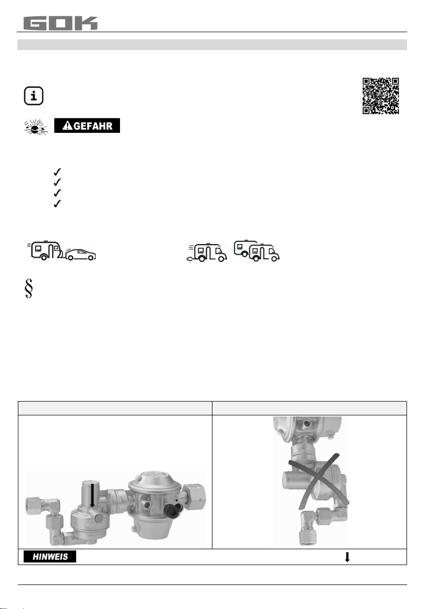
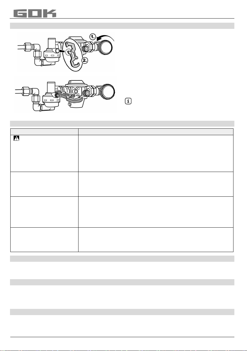
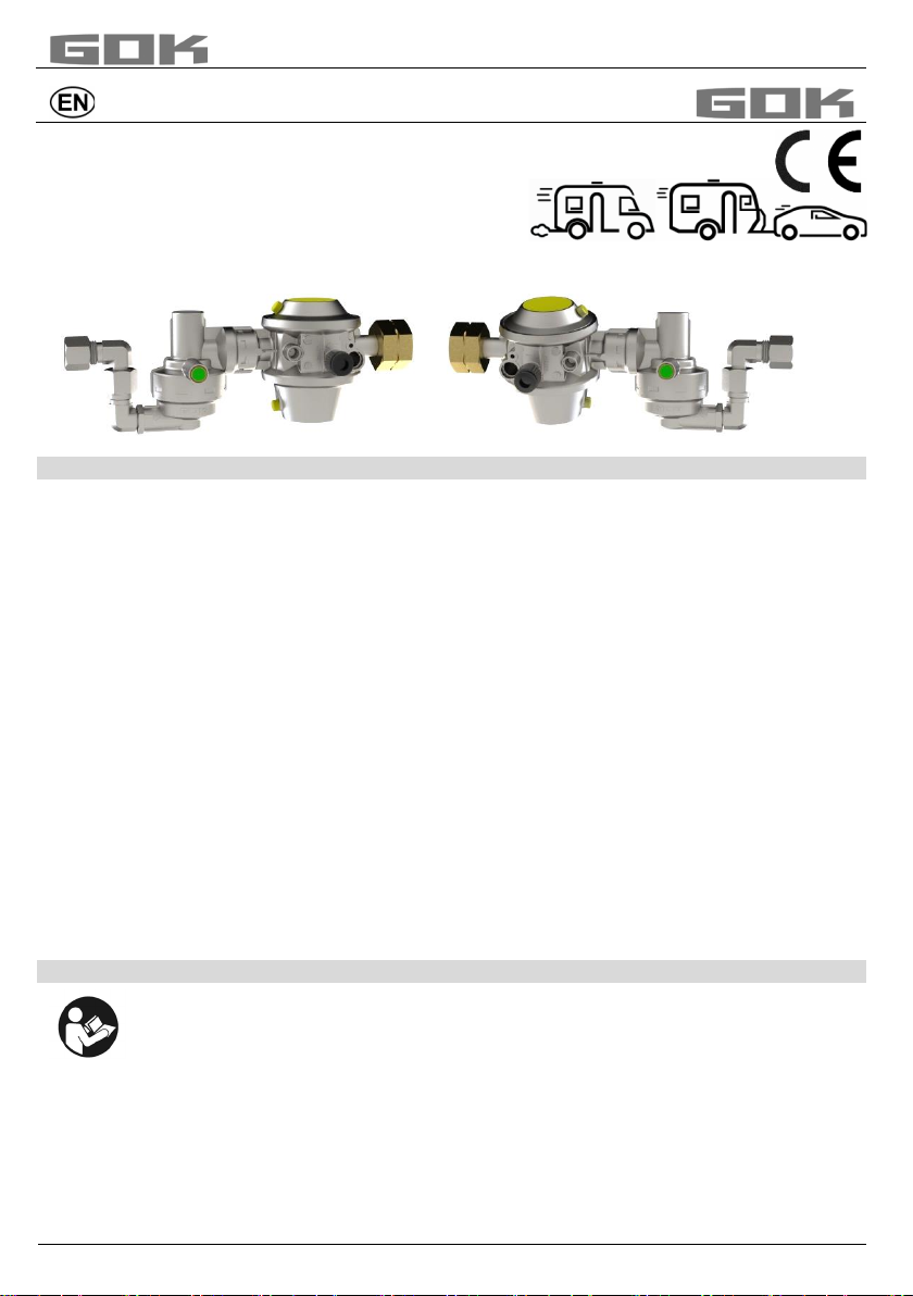
Für den sicheren Betrieb der Gasgeräte während der Fahrt muss diese Sicherheits-Gasdruck-
Regelanlage Caramatic DriveOne, bestehend aus einem zweistufigem Sicherheitsdruckregler
(S2SR) und einem mechanischen Crash-Sensor-Pendel direkt an das Gastankventil
angeschlossen werden.
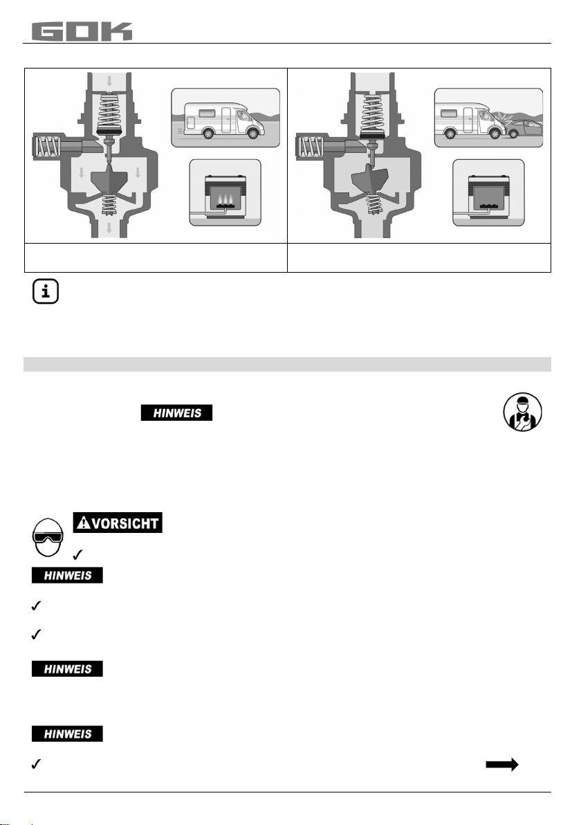
Der mechanische Crash-Sensor-Pendel, der bei einem Unfall mit einer waagerecht auf das
Auslöseelement einwirkenden Verzögerung von 3,5 g ± 0,5 g den Gasdurchgang absperrt,
erfüllt die Anforderungen für Sicherheit bei Betrieb während der Fahrt nach Verordnung (EG)
Nr. 661/2009 und UN/ECE-Regelung R 122 Heizungssysteme.
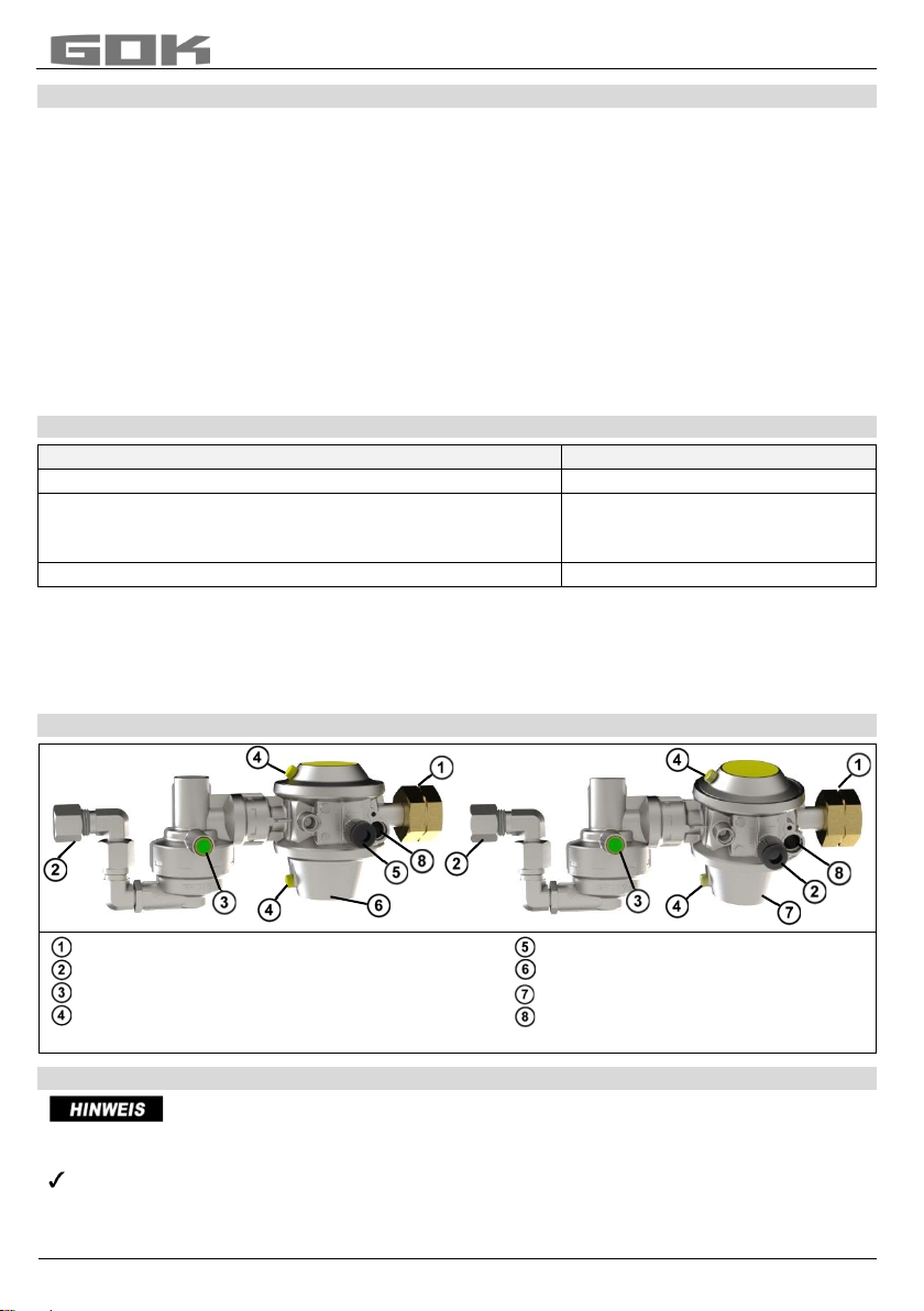
Der integrierte Druckregler der Caramatic DriveOne hält den auf dem Typschild angegebenen
Ausgangsdruck konstant, unabhängig von Schwankungen des Eingangsdruckes und
Änderungen von Durchfluss und Temperatur innerhalb festgelegter Grenzen.
Diese Montage- und Bedienungsanleitung beschreibt nicht die Montage eines
Gastanks und dessen Komponenten, wie Füllleitungen, Inhaltsanzeiger,
Sicherheits-, Gasentnahme- oder Füllventile!

Caramatic DriveOne
Artikel-Nr. 71 813 50 3 / 36
BESTIMMUNGSGEMÄSSE VERWENDUNG
Betriebsmedien
•Flüssiggas (Gasphase)
Eine Liste der Betriebsmedien mit Angabe der Bezeichnung,
der Norm und des Verwendungslandes erhalten Sie im Internet unter
www.gok.de/liste-der-betriebsmedien.
Ausströmendes Flüssiggas (Kategorie 1):
•ist extrem entzündbar
•kann zu Explosionen führen
•schwere Verbrennungen bei direktem Hautkontakt.
Verbindungen regelmäßig auf Dichtheit prüfen!
Bei Gasgeruch und UndichtheitFlüssiggasanlage sofort außer Betrieb nehmen!
Zündquellen oder elektrische Geräte außer Reichweite halten!
Entsprechende Gesetze und Verordnungen beachten!
Einsatzbereich
•Betrieb während der Fahrt oder bei stehendem Fahrzeug
•Caravans
•Motorcaravans
EN 1949 sowie in Deutschland DVGW-Arbeitsblatt G 607 beachten.
Bitte beachten Sie die gültigen nationalen Installationsvorschriften für Flüssiggasanlagen.
Betreiberort
•zum Anbau an einen Gastank:
•am Fahrzeugboden
•im Gastankkasten mit Lüftung
Einbauort
•zum Direktanschluss an einen Gastank
•an einen Gastank mit Gasflaschenanschluss
Einbaulage
Richtig
Falsch
Das Auslöseelement muss immer in senkrechter Position stehen.

Caramatic DriveOne
4 / 36 Artikel-Nr. 71 813 50
NICHT BESTIMMUNGSGEMÄSSE VERWENDUNG
Jede Verwendung, die über die bestimmungsgemäße Verwendung hinausgeht:
•z. B. Betrieb mit anderen Betriebsmedien, Drücken
•Verwendung von Gasen in der Flüssigphase
•Einbau entgegen der Durchflussrichtung
•Änderungen am Produkt oder an einem Teil des Produktes
•Verwendung bei Umgebungstemperaturen abweichend von: siehe TECHNISCHE DATEN
•Einbau abweichend von Einbaulage (siehe Seite 3)
•Betrieb im Innenbereich
•Einbau in Mobilheime und Sportboote
•Montage ohne Fachbetrieb, siehe QUALIFIKATION DER ANWENDER!
•Betrieb von Geräten während der Fahrt, die vom Hersteller nicht dafür freigegeben sind
•Betrieb von Kochgeräten oder Backöfen während der Fahrt
QUALIFIKATION DER ANWENDER
Tätigkeit
Qualifikation
MONTAGE, AUSTAUSCH
Fachpersonal, Kundendienst
BEDIENUNG, INBETRIEBNAHME,
AUSSERBETRIEBNAHME,WIEDERINBETRIEBNAHME,
INSTANDSETZUNG, ENTSORGEN,
Betreiber und Bediener
Dichtheitsprüfung
Sachkundiger*
*Sachkundige im Sinne dieser Technischen Regeln (Arbeitsblatt DVGW G 607 [A] sind
insbesondere in Deutschland die, durch den DVFG anerkannte Sachkundige,
die aufgrund ihrer Ausbildung, ihrer Kenntnisse und ihrer durch praktische Tätigkeit
gewonnenen Erfahrungen die Gewähr dafür bieten, dass sie die Prüfung ordnungsgemäß
durchführen.
AUFBAU
Eingangsanschluss
Ausgangsanschluss
grüner Druckknopf am Crash-Sensor-Pendel
Atmungsöffnung des Zweistufigen
Sicherheitsdruckreglers S2SR (ÜDS)
Prüfanschluss
Niederdruckregler 90°
Niederdruckregler (geneigt) 105°
Anschluss für Reglerheizung Eis-Ex
ANSCHLÜSSE
Anschlüsse können undicht werden, wenn sie verschmutzt oder beschädigt
sind. Deshalb müssen die Anschlüsse regelmäßig auf Dichtheit geprüft werden.
Gegebenenfalls das Produkt austauschen.
Alle Anschlüsse frei von Verschmutzungen halten, schon geringe Verunreinigungen
können zu Undichtheiten an den Anschlüssen führen.

Caramatic DriveOne
Artikel-Nr. 71 813 50 5 / 36
Eingang wahlweise
Handelsname und Abmessung
nach Norm
Montagehinweis
Großflasche (GF)
•mit Aluminium Dichtung
•G.4 = Gewinde W 21,8 x 1/14-LH
Schlüsselweite
SW 30
Sechskant
Kombinationsanschluss (Komb.A)
•mit Polyamid Dichtung
•G.5 = Gewinde W 21,8 x 1/14 LH
Schlüsselweite
SW 30
Sechskant
Kleinflasche (KLF)
•mit Überwurfmutter 5-Flügel
•G.12 = Gewinde W 21,8 x 1/14-LH ÜM
Handfest anziehen!
Ausgang
Handelsname und Abmessung
nach Norm
Montagehinweis
Schneidringverschraubung RVS
•H.9 = RVS 8, RVS 10
Alle G. und H. Anschlüsse nach EN 16129.
Dichtungen in den Anschlüssen (sofern vorgesehen) müssen unbeschädigt sein und
richtig in der Fassung liegen.
Anschluss
Handelsname und Abmessung
Montagehinweis
Prüfanschluss
Prüfschlauch G 1/4 LH-ÜM x Adapter für
Prüfeinrichtung x 750 mm
M11x1-UEM/PV
mit Innengewinde
VORTEILE UND AUSSTATTUNG
Sicherheits-Gasdruck-Regelanlage Caramatic
DriveOne zum Betrieb von flüssiggasbetriebenen
Gasgeräten im Caravan und Motorcaravan
während der Fahrt bestehend aus:
integriertem Niederdruckregler mit Zweistufigen
Sicherheitsdruckregler S2SR (ÜDS) und
mechanischen Crash-Sensor-Pendel mit
Bedienknopf.
Entspricht den berufsgenossenschaftlichen Anforderungen der DGUV Vorschrift 79
und ist für den Einsatz in gewerblich genutzten Caravans und Motorcaravans
geeignet!
•Prüfeinrichtung zur Dichtheitsprüfung der Flüssiggasanlage ohne Abbau des Produktes.
FUNKTIONSBESCHREIBUNG
Zweistufiger Sicherheitsdruckregler S2SR (ÜDS)
Der Zweistufige Sicherheitsdruckregler S2SR („S2SR“ Safety two Stages Regulator) ist eine
Kombination aus zwei, in Reihe geschalteten, Druckreglern. Fällt eine der beiden
Reglerstufen aus, z. B. durch Schmutz bzw. andere Fremdkörper am Ventil, übernimmt die
jeweils andere Reglerstufe eine Druckreduzierung auf maximal 150 mbar.

Caramatic DriveOne
6 / 36 Artikel-Nr. 71 813 50
Funktion Crash-Sensor-Pendel
Aktivierter Crash-Sensor-Pendel
Durchgang frei
Ausgelöster Crash-Sensor-Pendel
Durchfluß gesperrt
Der mechanische Crash-Sensor-Pendel sperrt bei einem Unfall mit einer waagerecht
direkt auf das Auslöseelement einwirkenden Verzögerung von 3,5 g ± 0,5 g den
Gasdurchgang ab. Diese Verzögerung entspricht bei einem mittleren Fahrzeug-
gewicht einer Aufprallgeschwindigkeit von ca. 15 bis 20 km/h auf ein festes
Hindernis.
MONTAGE
Vor der Montage ist das Produkt auf Transportschäden und Vollständigkeit zu prüfen.
Die MONTAGE ist von einem Fachbetrieb vorzunehmen! Siehe QUALIFIKATION
DER ANWENDER! Einbauort und Einbaulage beachten (siehe
BESTIMMUNGSGEMÄSSE VERWENDUNG).
Alle nachfolgenden Hinweise dieser Montage- und Bedienungsanleitung müssen vom
Fachbetrieb, Betreiber und Bediener beachtet, eingehalten und verstanden werden.
Voraussetzung für ein einwandfreies Funktionieren der Anlage ist eine fachgerechte
Installation unter Beachtung der für Planung, Bau und Betrieb der Gesamtanlage gültigen
technischen Regeln.
Verletzungsgefahr durch herausgeblasene Metallspäne!
Metallspäne können Ihre Augen verletzen.
Schutzbrille tragen!
Funktionsstörungen durch Rückstände!
Die ordnungsgemäße Funktion ist nicht gewährleistet.
Sichtkontrolle auf eventuelle Metallspäne oder sonstige Rückstände in den Anschlüssen
vornehmen!
Metallspäne oder sonstige Rückstände durch vorsichtiges Ausblasen unbedingt
entfernen!
Die Montage ist gegebenenfalls mit einem geeigneten Werkzeug
vorzunehmen. Bei Schraubverbindungen muss immer mit einem zweiten Schlüssel am
Anschlussstutzen gegengehalten werden.
Ungeeignete Werkzeuge, wie z. B. Zangen, dürfen nicht verwendet werden!
Beschädigung des Produktes durch falsche Einbaurichtung!
Die ordnungsgemäße Funktion ist nicht gewährleistet.
Einbaurichtung beachten (diese ist auf dem Produkt erkennbar mit einem Pfeil
gekennzeichnet)!

Caramatic DriveOne
Artikel-Nr. 71 813 50 7 / 36
Schraubverbindungen
Explosions-, Brand- und Erstickungsgefahr durch Undichtheit der Anschlüsse!
Kann durch Verdrehen des Produktes zu Gasaustritt führen.
Produkt nach der Montage und beim Nachziehen der Anschlüsse nicht mehr verdrehen!
Nachziehen von Anschlüssen nur in vollständig drucklosem Zustand!
Wenn der Druckregler in Fließrichtung nach einem anderen Druckregler
eingebaut wird, muss der Versorgungsdruckbereich mit dem geregelten Druckbereich des
davor liegenden Druckreglers übereinstimmen, unter Berücksichtigung des Druckverlustes
der dazwischen liegenden Rohrleitung.
DICHTHEITSKONTROLLE
Die Flüssiggasanlage muss vor der ersten Inbetriebnahme im Zuge von Überwachungs- und
Wartungsarbeiten, vor einer Wieder-Inbetriebnahme, nach wesentlichen Änderungen und
Instandsetzungsarbeiten durch einen Sachkundigen* auf Dichtheit geprüft werden.
Siehe QUALIFIKATION DER ANWENDER!
Prüfanschluss für Dichtprüfgerät
Im Rahmen der Druck- und Dichtheitsprüfung der Flüssiggasanlage kann am
Prüfanschluss ein Dichtprüfgerät angeschlossen werden.
1. Alle Absperrarmaturen der angeschlossenen
Verbraucher schließen.
2. Tankventil schließen.
3. Schraubkappe des Prüfanschlusses
abschrauben.
4. Prüfschlauch (Bestell-Nr. 02 618 06) an
Prüfanschluss anschrauben.
5. Dichtheitsprüfung mit Prüfpumpe mit
150 mbar durchführen.
6. Prüfschlauch abschrauben.
7. Anschluss mit schaumbildenden Mitteln nach EN 14291 (z. B. Lecksuchspray,
Bestell-Nr. 02 601 00) einsprühen.
8. Dichtheit am Anschluss prüfen, indem auf
weitere Blasenbildung im schaumbildenden Mittel geachtet wird.
9. Schraubkappe wieder auf Prüfanschluss schrauben.
*Sachkundige im Sinne dieser Technischen Regeln (Arbeitsblatt DVGW G 607 [A]
sind insbesondere in Deutschland die, durch den DVFG anerkannte Sachkundige,
die aufgrund ihrer Ausbildung, ihrer Kenntnisse und ihrer durch praktische Tätigkeit
gewonnenen Erfahrungen die Gewähr dafür bieten, dass sie die Prüfung ordnungsgemäß
durchführen.
BEDIENUNG
Benutzen Sie dieses Produkt erst, nachdem Sie die Montage- und Bedienungs-
anleitung aufmerksam gelesen haben.
Beachten Sie zu Ihrer Sicherheit alle Sicherheitshinweise dieser Montage- und
Bedienungsanleitung.
Verhalten Sie sich verantwortungsvoll gegenüber anderen Personen.

Caramatic DriveOne
8 / 36 Artikel-Nr. 71 813 50
INBETRIEBNAHME
1. Inbetriebnahme durch langsames Öffnen
der Gaszufuhr bei geschlossener
Absperrarmatur es angeschlossenen
Verbrauchers. Montage- und
Bedienungsanleitung des
angeschlossenen Verbrauchers
beachten!
Aktivierung des Crash-Sensor-Pendel
einmalig bei erster Inbetriebnahme:
2. Durch Eindrücken des grünen
Druckknopfes des Crash-Sensor-Pendel.
Dem Produkt beiliegenden Aufkleber im
sichtbaren Bereich der Sicherheits-
Gasdruck-Regelanlage anbringen.
FEHLERBEHEBUNG
Fehlerursache
Maßnahme
Gasgeruch
Ausströmendes
Flüssiggas ist extrem
entzündbar!
Kann zu Explosionen
führen.
Gaszufuhr schließen!
Keine elektrischen Schalter betätigen!
Nicht im Fahrzeug telefonieren!
Räume gut belüften!
Flüssiggasanlage außer Betrieb nehmen!
Fachbetrieb beauftragen!
Kein Gasdurchfluss
Tankventil oder Absperrarmaturen öffnen
Druckregler ist beschädigt, austauschen
Aktivierung des Crash-Sensor-Pendel
siehe INBETRIEBNAHME
Abnormales Flammenbild
bei fest eingestelltem
Druckregler
Nennausgangsdruck des Druckreglers mit
Nennanschlussdruck des angeschlossenen Verbrauchers
vergleichen:
bei Nichtübereinstimmung, Druckregler oder
Gasgerät austauschen
Zweistufiger
Sicherheitsdruckregler
S2SR (ÜDS), hat
angesprochen.
Am Gasgerät kurze Schübe Gas entweichen lassen,
um einen Druckausgleich zu erreichen.
Stellt sich kein Druckausgleich ein, Druckregler
austauschen.
AUSSERBETRIEBNAHME
Tankventil und dann Absperrarmaturen des Gasgerätes schließen.
Bei Nichtbenutzung der Flüssiggasanlage alle Ventile geschlossen halten.
INSTANDSETZUNG
Führen die unter FEHLERBEHEBUNG genannten Maßnahmen nicht zur ordnungsgemäßen
Wiederinbetriebnahme und liegt kein Auslegungsfehler vor, muss das Produkt zur Prüfung an
den Hersteller gesandt werden. Bei unbefugten Eingriffen erlischt die Gewährleistung.
WARTUNG
Das Produkt ist nach ordnungsgemäßer MONTAGE und BEDIENUNG wartungsfrei.

Caramatic DriveOne
Artikel-Nr. 71 813 50 9 / 36
AUSTAUSCH
Bei Anzeichen jeglichen Verschleißes und jeglicher Zerstörung des Produktes oder eines
Teiles des Produktes muss dieses ausgetauscht werden. Bei Austausch des Produktes
Schritte MONTAGE, DICHTHEITSKONTROLLE und INBETRIEBNAHME beachten!
Um unter normalen Betriebsbedingungen die einwandfreie Funktion der Installation zu
gewährleisten, wird empfohlen, die Einrichtung vor Ablauf von 10 Jahren nach dem
Herstellungsdatum auszutauschen.
Im gewerblichen Bereich nach DGUV Vorschrift 79 sind Teile von Verbrauchsanlagen,
die Verschleiß und Alterung*unterliegen, nach 8 Jahren auszutauschen. Dies gilt nicht,
wenn die ordnungsgemäße Beschaffenheit durch einen Sachkundigen bestätigt worden ist.
* Anlagenteile, die Verschleiß oder Alterung unterliegen, sind z.B. Membranen, automatische
oder manuelle Umschaltventile, Druckregler, Schlauchleitungen.
LISTE DER ZUBEHÖRTEILE
Caramatic TwoControl
Bestell-Nr.
Abdeckrahmen, Farbe: anthrazit
71 391 00
Reglerheizung Eis-Ex, Anschlusskabel 2 m
71 390 20
Informations- und Steuereinheit (Bedienpanel), Verbindungskabel 6 m
71 391 20
TECHNISCHE DATEN
Maximal zulässiger Druck PS
16 bar
Eingangsdruck p
0,3 bis 16 bar
Ausgangsdruck pd
wahlweise 30 oder 50 mbar
Nenndurchfluss Mg
1,5 kg/h
maximal erlaubte Druckabfall in der
nachgeschalteten Installation
∆P5
S2SR (ÜDS)
100 oder 150 mbar
Gehäusewerkstoff
Zinkdruckguss ZP0410
Umgebungstemperatur
-30 °C bis +60 °C
Weitere technische Daten oder Sondereinstellungen siehe Typschild des Produktes!
ENTSORGEN
Um die Umwelt zu schützen, dürfen unsere Produkte nicht mit dem Hausmüll
entsorgt werden.
Das Produkt ist über örtliche Sammelstellen oder Wertstoffhöfe zu entsorgen.
GEWÄHRLEISTUNG
Wir gewähren für das Produkt die ordnungsgemäße Funktion und Dichtheit
innerhalb des gesetzlich vorgeschriebenen Zeitraums. Der Umfang unserer
Gewährleistung richtet sich nach § 8 unserer Liefer- und Zahlungsbedingungen.
ZERTIFIKATE
Unser Managementsystem ist zertifiziert nach ISO 9001, ISO 14001 und
ISO 50001 siehe:
www.gok.de/qualitaets-umwelt-und-energiemanagementsystem.

Caramatic DriveOne
10 / 36 Artikel-Nr. 71 813 50
Assembly and operating manual
Caramatic DriveOne
safety gas pressure regulation device for gas tanks
for operating LPG-operated gas equipment
in the caravan and motor caravan while driving
CONTENTS
ABOUT THE MANUAL............................................................................................................................10
SAFETY ADVICE....................................................................................................................................11
GENERAL PRODUCT INFORMATION...................................................................................................11
INTENDED USE .....................................................................................................................................12
INAPPROPRIATE USE...........................................................................................................................13
USER QUALIFICATION..........................................................................................................................13
DESIGN ..................................................................................................................................................13
CONNECTIONS......................................................................................................................................13
ADVANTAGES AND EQUIPMENT .........................................................................................................14
FUNCTION DESCRIPTION ....................................................................................................................15
ASSEMBLY.............................................................................................................................................15
LEAK CHECK .........................................................................................................................................16
START-UP ..............................................................................................................................................17
TROUBLESHOOTING ............................................................................................................................17
SHUT-DOWN..........................................................................................................................................17
RESTORATION ......................................................................................................................................17
REPLACEMENT .....................................................................................................................................18
MAINTENANCE ......................................................................................................................................18
TECHNICAL DATA .................................................................................................................................18
LIST OF ACCESSORIES ........................................................................................................................18
DISPOSAL ..............................................................................................................................................18
WARRANTY ...........................................................................................................................................18
CERTIFICATE.........................................................................................................................................18
ABOUT THE MANUAL
•This manual is part of the product.
•This manual must be observed and handed over to the operator to ensure that
the component operates as intended and to comply with the warranty terms.
•Keep it in a safe place while you are using the product.
•In addition to this manual, please also observe national regulations, laws and
installation guidelines.
•Please keep these instructions in the vehicle!

Caramatic DriveOne
Artikel-Nr. 71 813 50 11 / 36
SAFETY ADVICE
Your safety and the safety of others are very important to us. We have provided many
important safety messages in this assembly and operating manual.
Always read and obey all safety messages.
This is the safety alert symbol.
This symbol alerts you to potential hazards that can kill or hurt you and others.
All safety messages will follow the safety alert symbol and either the word
“DANGER”, “WARNING”, or “CAUTION”. These words mean:
describes a personal hazard with a high degree of risk.
May result in death or serious injury.
describes a personal hazard with a medium degree of risk.
May result in death or serious injury.
describes a personal hazard with a low degree of risk.
May result in minor or moderate injury.
describes material damage.
Has an effect on ongoing operation.
describes a piece of information
describes a call to action
TECHNICAL CHANGES
All the information contained in this assembly and operating manual is the result of product
testing and corresponds to the level of knowledge at the time of testing and the relevant
legislation and standards at the time of issue. We reserve the right to make technical changes
without prior notice. Errors and omissions excepted. All figures are for illustration purposes
only and may differ from actual designs.
GENERAL PRODUCT INFORMATION
Safety during the operation of LPG-operated gas equipment while driving - with an LPG tank
If the gas equipment on board ( check suitability of the gas equipment here and observe
the operating manual of the installed gas equipment!) must also be operated while driving the
vehicle, a special safety device must be available which prevents gas escape in case of an
accident. This also applies for vehicles which are fitted with an LPG tank.
For the safe operation of this gas equipment, the safety gas pressure regulation device
consisting of a low pressure regulator with over-pressure safety device S2SR and mechanical
crash-sensor-pendulum is connected directly onto the LPG tank valve.
With the mechanical crash-sensor-pendulum which blocks the gas flow in case of an accident
with deceleration of 3.5 g ± 0.5 g, directly affecting the trigger element, the requirements for
safety during operation while driving are fulfilled in accordance with regulation (EC) no.
661/2009 and UN/ECE regulation R 122 on heating systems.
The integrated pressure regulator of the Caramatic DriveOne keeps the outlet pressure stated
on the type label constant within defined limits, regardless of fluctuations of the inlet pressure
and changes in flow rate and temperature.
This assembly and operating manual does not describe the assembly of an LPG
tank and its components such as filler lines, level gauges, safety valves, gas
removal valves or filler valves!

Caramatic DriveOne
12 / 36 Artikel-Nr. 71 813 50
INTENDED USE
Operating media
•LPG (gas phase)
You will find a list of operating media with descriptions, the relevant
standards and the country in which they are used in the Internet at
www.gok.de/liste-der-betriebsmedien.
Escaping liquid petroleum gas (category 1):
•is highly flammable
•may cause explosions
•severe burns in case of direct skin contact.
Regularly check connections for leak-tightness.
If you smell gas or detect a leak, shut the system down immediately.
Keep ignition sources and electrical devices out of reach.
Observe applicable laws and regulations.
Area of Application
for operating while driving or for a stationary vehicle
•Caravans
•Motor caravans
Observe EN 1949.
Observe the applicable national installation regulations for LPG systems.
Place of operation
•for installation on the LPG tank
•on the floor of the vehicle
•in the gas tank locker with ventilation
Installation location
•for direct connection to gas tank
•on a tank with a gas cylinder port
Installation position
Right
Wrong
The trigger element must always be in a vertical position.

Caramatic DriveOne
Artikel-Nr. 71 813 50 13 / 36
INAPPROPRIATE USE
All uses exceeding the concept of intended use:
•e.g. operation using different media, pressures
•use of gases in the liquid phase
•installation against the flow direction
•changes to the product or parts of the product
•use at ambient temperature varying from: see TECHNICAL DATA
•operate indoors
•installation in mobile homes and sports boats
•assembly without specialists, see USER QUALIFICATION!
•installation differs from installation position (see page 12)
•operation of devices while driving which have not been approved for this by the
manufacturer
•operation of cooking devices or ovens while driving
USER QUALIFICATION
Activity
Qualification
START-UP, SHUT-DOWN, RESTART,
RESTORATION, DISPOSAL,
user and operator
ASSEMBLY, REPLACEMENT,
qualified personnel, customer service
Leak check
expert*
*Experts are particularly those who, on the basis of their training, knowledge and experience
gained during practical activity, guarantee that they carry out the inspection properly.
DESIGN
Inlet connector
Outlet connector on the crash sensor
Green push button on the
crash-sensor-pendulum
Test connection
Low pressure regulator 90°
Low pressure regulator (inclined) 105°
Breather of S2SR Connection for Eis-Ex regulator heating
CONNECTIONS
Connections could become leaky, if they are contaminated or corrupted
Therefore, the connections must regularly be checked for leak-tightness.
Swap the product where appropriate.
Keep all connections free from contamination, even small amounts of dirt can cause
connections to leak.
Gaskets in the connections must not be damaged and be placed correctly in the frame.

Caramatic DriveOne
14 / 36 Artikel-Nr. 71 813 50
Inlet, optional
Trading name and dimensions
acc. to standard
Installation notes
Large cylinder connection GF
with aluminium gasket
G.4 = Thread W 21.8 x 1/14 lh
Spanner size 30
Hexagonal
Combinded fitting (Komb.A)
with polyamide gasket
G.5 = Thread W 21.8 x 1/14
Spanner size 30
Hexagonal
Small cylinder KLF
with 5-wing cap nut
G.12 = Thread W 21.8 x 1/14 ÜM
Tighten hand-tight.
Outlet
Trading name and dimensions
acc. to standard
Installation notes
Compression fitting RVS
H.9 = compr. fit 8 or compr. fit 10
All G. and H. according to EN 16129.
Connection
Commercial name and dimension
Assembly
information
Test connection
Test hose G 1/4 lh nut x adapter for
test device x 750 mm
M11x1-UEM/PV
with female thread
ADVANTAGES AND EQUIPMENT
Safety gas pressure regulation device
Caramatic DriveOne for operating LPG-
operated gas equipment in caravans and
motor caravans during the drive
consisting of: low pressure regulator with
over-pressure safety device S2SR and
mechanical crash-sensor-pendulum with
control knob.
•Test device for the leak testing of LPG systems without removing the product.

Caramatic DriveOne
Artikel-Nr. 71 813 50 15 / 36
FUNCTION DESCRIPTION
Safety two stages regulator S2SR
The safety two stages regulator S2SR is a combination of two series-connected pressure
regulators. If one of the two controller stages fails, e.g. because of dirt and other foreign
bodies in the valve, respectively, the other controller stage reduces the pressure to maximum
150 mbar.
Crash-sensor-pendulum function
Activated crash-sensor-pendulum
Flow rate free
Triggered crash-sensor-pendulum
Flow rate blocked
Operation while driving using the integrated mechanical crash-sensor-pendulum
which blocks the gas flow in case of an accident with deceleration of 3.5 g ± 0.5 g,
directly affecting the trigger element; with an average vehicle weight this corresponds
to crashing into a solid obstacle at about 15 to 20 km/h.
ASSEMBLY
Before assembly, check that the product is complete and has not suffered any damage during
transport. ASSEMBLY must be carried out by a specialised company.
See USER QUALIFICATION!
The specialised company and the operator must observe, comply with and understand all of
the following instructions in this assembly and operating manual. For the system to function
as intended, it must be installed professionally in compliance with the technical rules
applicable to the planning, construction and operation of the entire system.
Consider installation location and installation position (see instructions on INTENDED USE).
Risk of injuries due to blown-out metal chips!
Metal chips may cause eye injuries.
Wear safety goggles!
Malfunctions caused by residues! Proper functioning is not guaranteed.
Visually check that there are no metal chips or other residues in the connections!
It is important that metal chips or other residues are blown out!
Install with suitable tools, if required.
Regarding screw connections, use a second spanner to brace against the connection
nozzle. Do not use unsuitable tools, such as pliers.
Product damaged through incorrect installation direction
Proper functioning is not guaranteed.
Observe the installation direction (marked on the product with an arrow ).

Caramatic DriveOne
16 / 36 Artikel-Nr. 71 813 50
Screw connections
If connections leak, there is a danger of explosion, fire or suffocation!
Gas may escape if the product is turned.
Do not turn the product after it has been installed and the connections have been
tightened.
Tighten connections only when they are not pressurised.
The gaskets at the inlet connections (if provided) must be replaced when re-assembling!
Make sure that the gaskets sit properly in the mounting and that the screws are tightened.
If the pressure regulator is installed in the flow direction downstream from
another pressure regulator, the supply pressure range must correspond to the regulated
pressure range of the first pressure regulator, with consideration of the pressure loss in the
piping between the two devices.
LEAK CHECK
The liquefied gas unit must be checked for leaks by an expert* before the first start-up, during
checking and maintenance work, before the re-start and after important changes and repair
work. See USER QUALIFICATION!
Test connection for leak tester
A leak tester can be connected to the test connection for pressure and leak testing of the LPG
system.
1. Close all shut-off fittings on the connected
consuming devices .
2. Close the tank valve.
3. Unscrew the screw cap of the test connection.
4. Screw the test hose (order no. 02 618 06) on
the test connection.
5. Carry out leak testing with the test pump at
max. 150 mbar.
6. Unscrew the test hose and screw the screw cap back onto the test connection.
7. Spray the connection with a foam producing substance according to EN 14291
(e.g. leak detector spray, order no. 02 601 00).
8. Check the leak-tightness at the connection by seeing whether bubbles form
in the foam producing substance.
9. Screw the screw cap back onto the test connection.
Observe EN 1949.
Observe the applicable national installation regulations for LPG systems.
*Experts are particularly those who, on the basis of their training, knowledge and experience
gained during practical activity, guarantee that they carry out the inspection properly.
OPERATION
Use this product only when you have carefully read the assembly and operating
manual.
For your own safety, observe all the safety messages in this assembly and
operating manual.
Please also consider the safety of others.

Caramatic DriveOne
Artikel-Nr. 71 813 50 17 / 36
START-UP
1. Start the system by slowly opening the gas
supply while the shut-off fitting of the
connected consuming devices remains
closed. Observe the assembly and operating
manual of the connected consumption
equipment!
Activate the crash-sensor-pendulum the first
time you start the system:
2. By pushing the green push button on the
crash-sensor-pendulum.
Apply the adhesive accompanying the
product to a visible area of the Caramatic
DriveOne.
TROUBLESHOOTING
Fault cause
Action
Gas smell
Leaking LPG is extremely
flammable.
Can cause explosions.
Close the gas supply.
Do not use any electric switches.
Do not use a phone in the vehicle.
Ventilate rooms well.
Shut down the LPG system.
Contact a specialised company.
No gas flow.
Open the tank valve or the shut-off fittings.
Pressure regulator is defective, replace.
Activation of the crash-sensor-pendulum see START-UP.
Abnormal flame pattern of
non-adjustable pressure
regulator
Compare the nominal outlet pressure of the pressure
regulator with the nominal inlet pressure of the connected
consuming device:
if they do not correspond, replace the pressure regulator
or the gas appliance
Safety two stages regulator
S2SR reacted.
Allow short bursts of gas to escape from the gas
equipment to achieve pressure compensation.
If no pressure compensation is achieved, replace the
pressure regulator.
SHUT-DOWN
Close the tank valve and then the shut-off devices of the consumer unit. When the system is
not used, all valves must be kept closed.
RESTORATION
If the actions described in TROUBLESHOOTING do not lead to a proper restart and if there is
no dimensioning problem, the product must be sent to the manufacturer to be checked. Our
warranty does not apply in cases of unauthorised interference.

Caramatic DriveOne
18 / 36 Artikel-Nr. 71 813 50
REPLACEMENT
If there is any sign of wear or if the product or parts thereof are damaged, it must be replaced.
When the product has been replaced, observe the steps ASSEMBLY, LEAK TESTING and
START-UP.
To ensure that the installation works faultlessly under normal operating conditions, it is
recommended that you replace the device within 10 years of the date of manufacture.
MAINTENANCE
Upon proper ASSEMBLY and OPERATION, the product is maintenance-free.
TECHNICAL DATA
Maximum admissible pressure
PS 16bar
Inlet pressure p
0.3 to 16bar
Nominal regulated pressure
pd alternatively 30 or 50mbar
Nominal flow rate Mg
1,5 kg/h
Maximum permitted pressure drop in
the downstream installation
ΔP5
S2SR (OPC)
100 or 150mbar
Housing material
die-cast zinc ZP0410
Ambient temperature
-30°C to +60°C
For additional technical data or special settings, see type label of the product!
LIST OF ACCESSORIES
Caramatic TwoControl
Order no.
Cover frame, colour: anthracite
71 391 00
Eis-Ex regulator heating, 2m connection cable
71 390 20
Information and control unit (control panel), 6m connection cable
71 391 20
DISPOSAL
To protect the environment, our products may not be disposed of along with
household waste.
The product must be disposed of via a local collection station or a recycling station.
WARRANTY
We guarantee that the product will function as intended and will not leak during
the legally specified period. The scope of our warranty is based on Section 8 of
our terms and conditions of delivery and payment.
CERTIFICATE
Our management system is certified according to ISO 9001, ISO 14001 and
ISO 50001, see:
www.gok.de/qualitaets-umwelt-und-energiemanagementsystem.

Caramatic DriveOne
Artikel-Nr. 71 813 50 19 / 36
Notice de montage et de service
Caramatic DriveOne
installation de détente de gaz de sécurité pour réservoirs de gaz,
pour le fonctionnement d'appareils à gaz fonctionnant au gaz liquéfié
dans des caravanes et camping-cars pendant le trajet
TABLE DES MATIÈRES
À PROPOS DE CETTE NOTICE.............................................................................................................19
CONSIGNES DE SÉCURITÉ..................................................................................................................20
INFORMATIONS GÉNÉRALES SUR LE PRODUIT................................................................................20
GARANTIE..............................................................................................................................................21
UTILISATION CONFORME ....................................................................................................................21
UTILISATION NON CONFORME............................................................................................................21
QUALIFICATION DES UTILISATEURS ..................................................................................................22
STRUCTURE ..........................................................................................................................................22
RACCORDS ...........................................................................................................................................22
AVANTAGES ET ÉQUIPEMENT ............................................................................................................23
DESCRIPTION DU FONCTIONNEMENT ...............................................................................................23
MONTAGE..............................................................................................................................................24
CONTRÔLE D’ÉTANCHÉITÉ..................................................................................................................25
MISE EN SERVICE.................................................................................................................................26
COMMANDE...........................................................................................................................................26
DÉPANNAGE..........................................................................................................................................26
MISE HORS SERVICE............................................................................................................................26
RÉPARATION.........................................................................................................................................26
REMPLACEMENT ..................................................................................................................................27
ENTRETIEN............................................................................................................................................27
DONNÉES TECHNIQUES ......................................................................................................................27
LISTE DES ACCESSOIRES ...................................................................................................................27
ÉLIMINATION .........................................................................................................................................27
MODIFICATIONS TECHNIQUES............................................................................................................27
CERTIFICATS.........................................................................................................................................27
À PROPOS DE CETTE NOTICE
•La présente notice fait partie intégrante du produit.
•Cette notice doit être observée et remise à l’exploitant en vue d’une exploitation
conforme et pour respecter les conditions de garantie.
•À conserver pendant toute la durée d'utilisation.
•Outre cette notice, les prescriptions, lois et directives d'installation nationales
doivent être respectées.
•Conserver les présentes instructions dans le véhicule !

Caramatic DriveOne
20 / 36 Artikel-Nr. 71 813 50
CONSIGNES DE SÉCURITÉ
Nous attachons une importance cruciale à votre sécurité et à celle d’autrui. Aussi
avons nous mis à votre disposition, dans cette notice de montage et service, un grand
nombre de consignes de sécurité des plus utiles.
Veuillez lire et observer toutes les consignes de sécurité ainsi que les avis.
Voici le symbole de mise en garde. Il vous avertit des dangers éventuels
susceptibles d’entraîner des blessures ou la mort – la vôtre ou celle d’autrui. Toutes
les consignes de sécurité sont précédées de ce symbole de mise en garde, lui-
même accompagné des mots « DANGER », « AVERTISSEMENT » ou
« ATTENTION ». Voici la signification de ces termes :
signale un danger pour une personne comportant un niveau de risque élevé.
Peut entraîner la mort ou une blessure grave.
signale un danger pour une personne comportant un niveau de risque moyen.
Peut entraîner la mort ou une blessure grave.
signale un danger pour une personne comportant un niveau de risque faible.
Peut entraîner une blessure légère à moyenne.
signale un dommage matériel.
A une influence sur l’exploitation en cours.
signale une information
signale une incitation à agir
INFORMATIONS GÉNÉRALES SUR LE PRODUIT
Sécurité pour le fonctionnement d'appareils à gaz liquéfié pendant le trajet - avec un
réservoir de gaz
Si les appareils à gaz se trouvant à bord (( vérifier que les appareils à gaz sont prévus à
cet effet et respecter la notice d'utilisation des appareils à gaz installés !) doivent également
fonctionner pendant le trajet du véhicule, un dispositif de sécurité spécial doit être présent afin
d'empêcher toute fuite de gaz dans le cadre d'un accident. Ceci s’applique également aux
véhicules équipés d’un réservoir de gaz.
Afin de garantir un fonctionnement sécurisé de ces appareils à gaz, le installation de détente
de gaz de sécurité Caramatic DriveOne comprenant un détendeur basse pression avec
dispositif de sécurité contre surpression S2SR et d'un pendule du capteur de collision
mécanique est directement raccordée au réservoir de gaz est directement raccordée au
réservoir de gaz. Avec le pendule du capteur de collision mécanique qui, en cas d'accident,
coupe le circuit de gaz avec un retard de 3,5 g ± 0,5 g agissant directement sur l'élément de
déclenchement, les exigences en matière de sécurité lors du fonctionnement pendant le
trajet, établies par le règlement (CE) n° 661/2009 et le règlement UN/ECE R 122 relatif aux
systèmes de chauffage, sont satisfaites.
Le détendeur de pression intégré du Caramatic DriveOne maintient la pression de sortie à
une valeur constante spécifiée sur la plaque signalétique, indépendamment des variations de
la pression d'entrée ainsi que des changements du débit et de la température dans les limites
fixées.
La présente notice de montage et de service ne décrit pas le montage d'un
réservoir de gaz et des composants de ce dernier, tels que les conduites de
remplissage, la jauge, les robinets de sécurité, de soutirage ou de
remplissage !
Table of contents
Languages:
Other GOK Water Filtration System manuals
Popular Water Filtration System manuals by other brands

AmeriWater
AmeriWater MediQA MSP Operation & maintenance manual

WALKER FILTRATION
WALKER FILTRATION 20HP25 Installation & maintenance instructions

Pentair
Pentair FLECK 9000 SXT Installer manual

Whirlpool
Whirlpool WHEUFF Installation and operation manual

Weh
Weh TSF2 H2 operating instructions

HEBU medical
HEBU medical HB9304 operating manual