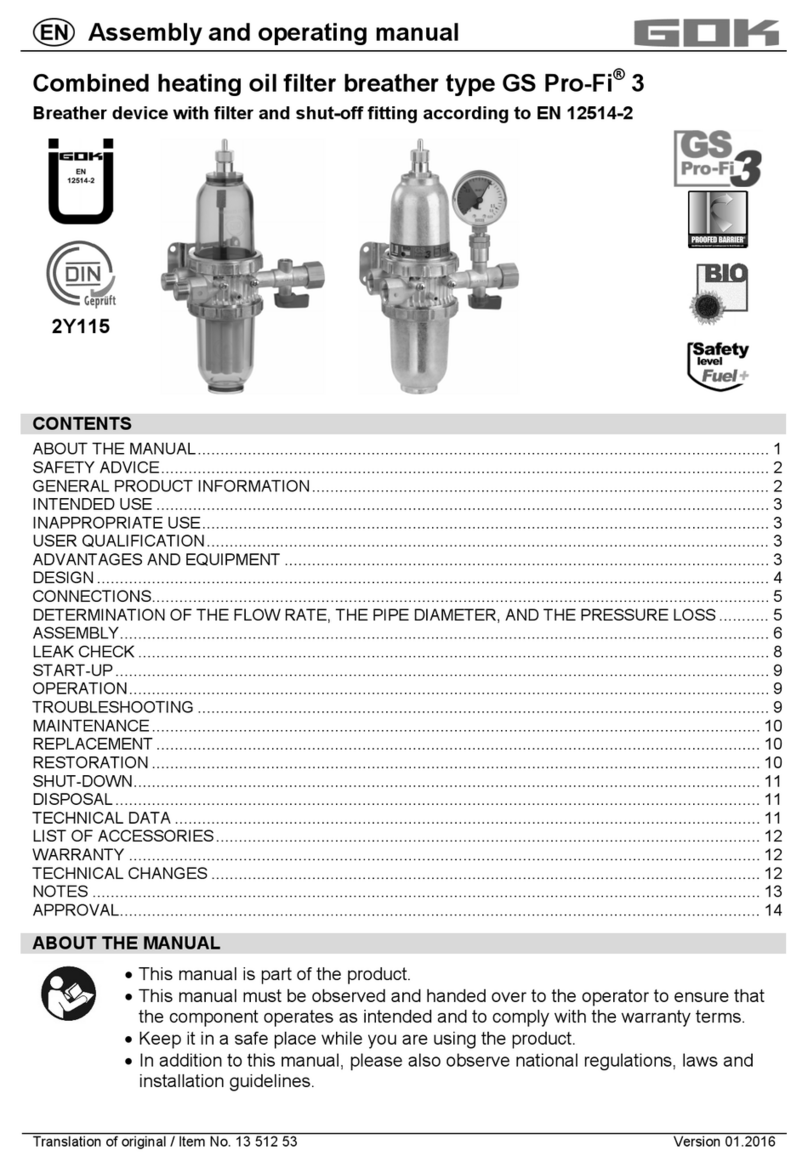
GOK 13512 Series User manual

Installation and Operating Manual
Art. No. 13512-.../13513-...
Version 10.2012 Page 1
Fuel Oil Filter and Deaerator
Combination
2Y115/05
Deaeration Device with Filter and
Quick-Acting Valve acc. to EN 12514-2
Legend
①– Deaerator screw
②– Deaerator cover
③– Retaining ring
④– With or without Vacuum gauge (as a special version,
optionally also available with rotating connection),
⑤– Connection for tank line (suction line)
⑥– Quick-acting valve
⑦– Filter element
⑧– Filter cover
⑨– Fixing plate for wall installation
⑩– Connection of burner return line
⑪– Connection of burner flow line
⑫– Screw heads for mounting the fixing panel
⑩+ ⑪– optionally available with female thread
This deaerator can be used with fuel oil
with bio-components (see OPERATING
MEDIA)
CONTENT
General
Safety note
Design
Operating media
Connections
Labeling
Installation
Page 1
Page 1
Page 2
Page 2
Page 2
Page 2
Page 3
Start-up
Operation
Performance check
Maintenance
Overhaul / Repair
Additional technical data
List of accessories
Page 5
Page 5
Page 6
Page 6
Page 6
Page 7
Page 7
GENERAL
The fuel oil filter-and-deaerator combination GS Pro-Fi 3 is a Professional Filter deaeration system of the 3.
generation. It is designed as a closed system (“Geschlossenes System” - GS). It corresponds to the
requirements of EN 12514-2:2000 the code of practice for oil firing according to BS 5410-1 and ‘OFTEC
Technical Book 3 chapter 2.2.
In the GS Pro-Fi 3, a deaeration device is combined with a filter and a quick-acting valve connected upstream. It
filters the fuel oil while simultaneously discharging the gases released during the suction process. The gases are
not “deaerated“ into the environment but within the “Closed System” via the burner nozzle into the combustion
chamber. Thus, the system works odour-free.
It is intended only for installation into the suction line of supplying units which are designed in single-pipe system
with return feed for suction drain operation.
For usage to the intended purpose and ensuring the warranty, please observe this Installation and Operating
Manual and give it to the operator.
SAFETY NOTE:
Operating media as for example fuel oil pollute water! Any material leakage occurring during
maintenance must be collected. Observe the respective legal regulations on water pollution
control! The GS Pro-Fi 3 must be installed, commissioned, serviced and repaired by skilled
craftsmen. It is imperative that you observe the following notes on installation and operation!
①
②
③④
⑤
⑥
⑦
③
⑫
⑩
⑪
⑨
⑧

Installation and Operating Manual
Art. No. 13512-.../13513-...
Version 10.2012 Page 2
DESIGN
The GS Pro-Fi 3 consists of the following individual assemblies:
•Deaeration device within the deaerator cover and the housing
•Deaerator screw ①at deaerator cover ②,only used during start-up
•Filter ⑦inside the filter cover ⑧,filter elements consisting of any of the following materials: felt, sintered
plastic, stainless steel, easy-change filter, or micro-filter
•Filter cover and filter are available either in standard or in long version (with the exception of easy-change
filter and micro-filter)
•Check valve in the input port ⑤
•Quick-acting valve ⑥integrated in the housing
•Fixing panel ⑨for wall mounting in both installation directions
•Connections ⑤, ⑩, and ⑪for mounting of pipe or hose lines, depending on the design
OPERATING
MEDIA
Kerosene C2 and Gas oil D acc. to BS 2869
Kerosene C2 and Gas oil D with max. 30 % FAME acc. to EN 14213 or EN 14214
FAME acc. to EN 14213 or EN 14214
Bio-Liquids for combustion purposes acc. to OPS 24
Diesel acc. to EN 590
CONNECTIONS
Connection
Dimension
according to standard
④
Manometer
blindscrew
Female thread G 1/8 with O-ring EN ISO 228-1
⑤Tank line
(tank side)
Female thread G 3/8 EN ISO 228-1
Cutting ring connection RVS 6 (RVS 8, RVS 10) EN ISO 8434-1
GOK universal connection fittings UA 6/8/10 mm
Screwed clamping ring connection, brass
Initial testing of construction
products by a notified body (ÜHP)
⑪Burner flow line Female thread G 3/8 or
male thread G 3/8 A with A-KN (60° inside cone) EN ISO 228-1
prEN 12514-4:2009
⑩Burner return line
LABELING
The GS Pro-Fi 3 bears the following labels:
Label
Significance
Explanation
Manufacturer’s sign
GOK Regler- und Armaturen-Gesellschaft mbH & Co. KG
Tank line ⑤Connection of the pipeline on container side, flow direction indicated
Burner flow line ⑪Connection for pipe/hose line, flow direction indicated
Burner return line ⑩Connection for pipe/hose line, flow direction indicated
The label on the upper filter cover shows the flow diagram and the version of the GS Pro-Fi 3
with the stated article number.
The Ü sign is the evidence of initial testing of construction products by a notified body (ÜHP)
pursuant to Construction Regulation List A Part 1.
Test report no. S 51 2005 Z2 by TÜV Immissionsschutz und Energiesysteme GmbH
DIN CERTCO Certificate of Conformity, register number 2Y115/05 with EN 12514-2:2000
Certification Program Oil Supply Systems for Oil Burners
PA/4186/05 - Test report quality label “PROOFED BARRIER“ by Fraunhofer-Institut
Verfahrenstechnik und Verpackung of 2005-12-15 / see Annex 2
This device meets the requirements of the OFTEC OIL FIRING PRODUCT STANDARD
OPS 23 :11-2007 / see Annex 1

Installation and Operating Manual
Art. No. 13512-.../13513-...
Version 10.2012 Page 3
INSTALLATION
Check the GS Pro-Fi 3 for completeness and any transport damages before start of the installation.
A skilled person must be commissioned to install the unit. This requirement also applies to commissioning,
maintenance and repairs.
Notes on installation
Expert installation under observation of the technical regulations for planning, construction and operation of the
system as a whole is the precondition for faultless functioning of the fuel oil system.
Above all, make sure to observe the following:
•The pipeline from the tank must be installed in a frost-resisting manner; if necessary, provide for technical
equipment for heating with installation in domes or in the open air.
•For installation, use only open-end spanners of corresponding width. No gas wrenches may be used.
•Mount the device free of any tensile, bending, or torsion stress
•Before installation, check the connections visually for metal chips or other matter. Be sure to remove any
such matter (e.g. by blowing out) to avoid malfunctioning.
•The bleeder line dimensions should provide for a mean fuel flow rate of 0.2 to 0.5 m/s. If the diameter of the
pipes is too large, low flow rates occur which can result in formation of undesirable gas bubbles.
Calculation of the flow rate w in m/s
Installation in a
⇒
single-pipe system
two-pipe system
flow system
Calculation
.
V
=
- volume flow of
operating medium in
l/h
≈
combustion capacity
in kW / 10
=
Gearwheel
capacity of oil
burner pump
=
flow rate of the
feed pump
ID – inside diameter of pipe (mm)
For fuel oil appliances, the following mean flow rate applies:
Suction drain operation: 0.2 ÷0.5 m/s Pressure operation: 1.0 ÷1.5 m/s
Under observation of suction line length,
geodesic height, suction height and fuel
oil volume flow rate, the following
approximate values are recommended
for selecting a pipeline ⇒
fuel oil ID
Cu pipe •Lower flow rates in suction
operation cause formation of
undesirable gas bubbles.
•Pipelines with inside
diameters smaller than 4 mm
are not recommended!
1
÷
10 l/h
4 mm
8
÷
45 l/h
6 mm
25
÷
130 l/h
8 mm
90 ÷170 l/h 10 mm
Or see
acc. OFTEC Technical Book 3 chapter 2.2.6
Maximum total pressure loss of all components in the suction line = 0.4 bar
See the diagram for pressure loss of the GS Pro-Fi 3 as a function of fuel oil volume flow and filter element used.
w= 0,3537
•
.
V
/ ID2

Installation and Operating Manual
Art. No. 13512-.../13513-...
Version 10.2012 Page 4
The installation of the GS Pro-Fi 3 is permitted:
•in single-pipe oil-fired installations with return feed (suction line)
•
above and below the oil tank top height
Installation position and fixing
The installation position is always vertical: filter cover ⑧with filter element ⑦below, deaerator cover ②on top.
The GS Pro-Fi 3 is supplied with a pre-mounted fixing panel ⑨for wall mounting. It can optionally be mounted at
the opposite side of the housing. You do not need to remove the screws ⑫. Simply pull the fixing panel down,
take it off, attach it at the opposite side of the housing and push it back up again.
Installation of the connections of individual components
The connections for the tank line ⑤, the burner flow line ⑪and the burner return line ⑩differ in accordance with
the selected option.
Connections with female threads are not designed for flat packings. Please always use the enclosed O-rings for
this option - see Installation of the connections female thread G3/8
In all installation work, hold up with open-end spanner SW 24 at the integrally cast connecting
branch, or with the appropriate open-end spanner at the respective screwed connection. Avoid
any twisting or torsion of the device. Be careful with the plastic parts!
Installation of the connections with female thread G 3/8
Female thread G 3/8 acc. to EN ISO 228-1
O-ring (enclosed) = seal!
Single-screw connection, e.g. screwed plug
EN ISO 1179-4 or prEN 12514-4:2009 shape
Installation of a screwed connection with brass or steel cutting ring (for your information)
Component
Connection via
Explanations
GS Pro-Fi 3
Connecting branch
in RVS 6, 8, 10, or 12, optionally
available as factory-mounted version Screwed connection with brass or steel
cutting ring acc. to EN ISO 8434-1
Connection Pipe or socket piece of the connecting
hose line with 6, 8, 10, or 12 mm
outside diameter
•copper pipe, e.g. according to EN 1057
•Aluminum pipe, e.g. according to EN 1746
•Precision steel pipe, e.g. according to EN 10305-1,
steel cutting ring recommended!
IMPORTANT: Always use a reinforcing insert for copper and aluminum pipe!
Installation pursuant to the GOK Installation Manual for screwed connections with cutting rings according to
EN ISO 8434-1. Available for download from www.gok-online.de under “Service“.
Installation of the GOK Universal connection fitting type UA
The female thread can also take the GOK universal
connection set type UA, which corresponds to a
compression joint type G acc. to prEN 12514-4:2009
Annex D.
Piping used:
Copper pipe with outer diameter 6, 8 or 10 mm, e.g. acc.
to EN 1057
Installation acc. to Installation Manual for GOK clamp ring connection: UA Universal connection fittings.
Available for download from www.gok-online.de under “Service“.
Installation of male thread G 3/8 A with KN (60 ° inside cone) Recommended tightening torque: 10 Nm
Component
Connection via
Explanations
GS Pro-Fi 3 Connecting branch to
housing, with inside cone KN
Pipe thread: cylindrical male thread G 3/8 in tolerance
class A according to EN ISO 228-1 with 60° inside cone
Connection Hose fitting with ball nipple
connection and union nut
Union nut with female thread G 3/8 according to
EN ISO 228-1, hose nozzle with ball seal

Installation and Operating Manual
Art. No. 13512-.../13513-...
Version 10.2012 Page 5
Optional installation of metal filter cover PS = 16 bar
•Turn retaining ring anti-clockwise to loosen it, hold and remove filter cover
•Take care not to damage the O-ring. Replace it if necessary (a new O-ring must be oiled!)
•Hold the metal filter cover and the O-ring in position and tighten by hand by turning the retaining ring
clockwise.
•Check for existing leaks, make sure no leaks will occur!
START-UP
If a pressure test is required before starting up the oil-fired installation, e.g. according to OFTEC Technical Book
3 section 5, the GS Pro-Fi 3 can be subjected to a test pressure of a maximum of 6 bar with plastic cover, or 16
bar with metal cover. Avoid any pressure increase beyond 6 bar or 16 bar caused by heating of the test medium.
Higher test pressures can damage the GS Pro-Fi 3.
Before start-up, the GS Pro-Fi 3 and all the connections must be checked for leaks. This test can be included in
the pressure, leak, or function test of the oil-fired installation. Any leaks must be sealed, e.g. by re-assembly of
the connections with new conical nipples or tightening of the screwed connections.
Observe the safety information under MAINTENANCE!
Unless defined otherwise in the start-up
instructions of the burner/furnace
manufacturer, proceed as follows:
Deaerate the installed oil lines (burner flow
and return lines) and the deaerator with a
suction pump and fill them with fuel. To this
end, open the quick-acting valve and the
deaeration screw . Connect the suction
pump directly at the deaeration screw by
means of the enclosed adapter, Art. no.
13610-60. We recommend continuing the
suction process until the upper cover is filled
with oil as well. After that, re-tighten the
deaeration screw.
OPERATION
In ongoing operation of the oil-fired installation, the GS Pro-Fi 3 does not require any attendance. Set the
integrated quick-acting valve - a ball valve - to the ‘open’position by turning the handle in flow direction, as
shown in the figure on Page 1.
Turn the handle of the quick-acting valve to ‘closed’ position – vertical to the flow direction – for longer standstill
periods or MAINTENANCE measures.
Due to the intelligent design of the GS Pro-Fi 3, the full fuel oil column will be available on burner start-up without
any noticeable air particles.
INFORMATION ON THE FILTER ELEMENT :
There is no universal filter element. Select a filter element according to the specification of the burner
manufacturer, taking into account filter fineness and the respective operating conditions. The IWO Institute for
Economically Efficient Fuel Oil Heating Systems recommends filter elements of sintered plastic of a mesh width
of 30 to 75 µm. For oil-fired installations with so-called “low NOx burners“ and burners of lower thermal output,
GOK filter elements FEINFILTERUNG of a mesh width of < 35
µ
m are recommended.
SAFETY FUNCTION
In case of hose rupture in the flow or return line , the aspired ambient air will cause the burner to go to
“lock out” state.
For pressure testing, unscrew the manometer blind screw and screw in the manometer G 1/8.
Make sure that the O-ring remains in the manometer blind screw.
After testing, unscrew the manometer and screw in the manometer blind screw with O-ring.
Diagram:
Fuel oil filter-and-deaerator combination GS Pro-Fi 3

Installation and Operating Manual
Art. No. 13512-.../13513-...
Version 10.2012 Page 6
PERFORMANCE CHECK
Provided the construction and the pipeline dimensioning are correct, the air cushion formed in the upper cover
during start-up will disappear fast. If, after longer period of operation, air is released in the deaerator cover , or
if the burner goes to lock out state, there is a leak in the oil line. More air is aspired than can be handled by
addition of air to the fuel oil. The leak must be repaired to avoid any risk of fuel oil leakage while the installation is
at standstill.
A clearly audible noise from the burner pump can be a sign of a clogged-up filter element . See
MAINTENANCE for replacing the filter element.
Filter cover not filled to the top
Air and lightly volatile oil components may outgas from the operating medium and collect before the moistened
filter element. This applies in particular to single-pipe filters and low flow volumes. However, the invisible interior
of the filter element is completely filled with the operating medium, so that safe operation is not affected if the
filter cover is not filled to the top.
Should the filter cover level drop or should the cover fall dry, there is a leak in the system.
MAINTENANCE
The following checks are recommended in the course of annual maintenance or after prolonged standstill:
•Check the deaerator and the connections for leaks
•Visually check the plastic filter cover and the deaerator cover for damage: tears or deformation
•
Replace the filter element
A damaged or destroyed plastic filter cover must be replaced for a new one. Steps to take when changing the
filter element:
The deaerator cover can only be replaced as a complete assembly, i.e. together with deaerator screw ①.
If the system has been submerged, any outside soiling of the filter should be cleaned off with a commercially
available household cleaning agent.
Do not use cleaning agents containing solvents as they might damage the plastic filter cover or other plastic
parts, e.g. the handle. For spares, see List of spare parts
Replacing the filter element
Switch the burner off and stop the oil column from returning into the oil storage container - close the stop valves.
Use the collecting device!
Type 500
Type 500 with easy-change filter
Turn retaining ring anti-clockwise to loosen it, hold and
remove filter cover Loosen the easy-change filter by turning it
anti-clockwise
Hold up the adapter with open-end spanner
SW 70.
Take care not to damage the O-ring. Replace it if necessary (a
new O-ring must be oiled!) Only use red GOK O-rings!
Unscrew the old filter element
Clean the sealing area and the O-ring
Oil the O-ring of the new easy-change filter
Insert new filter element , ensure tight fit.
Hold the filter cover and the O-ring in position and tighten by
hand by turning the retaining ring ③clockwise. Hold the new easy-change filter in position
and tighten it by turning it clockwise.
Check for existing leaks, make sure no leaks will occur!
Take special care to clean lengths of line to be installed downstream of the filter thoroughly before mounting.
To continue, see START-UP and OPERATION
OVERHAUL / REPAIR
If the measures explained under the headings START-UP, OPERATION and MAINTENANCE fail to achieve
regular re-START, and provided the construction and dimensions are correct, the GS Pro-Fi 3 must be removed
and sent to the manufacturer’s for a check-up. Any unauthorized handling will result in loss of the qualification
approval and any warranty claims.

Installation and Operating Manual
Art. No. 13512-.../13513-...
Version 10.2012 Page 7
ADDITIONAL TECHNICAL DATA
Minimum/maximum
permissible temperature TS
-10 °C ÷+60 °C
(operating medium and environment)
Maximum permissible
pressure
PS = 6 bar with plastic cover
PS = 10 bar with easy-change
filter element
PS = 16 bar with metal cover
Material of housing
Metal ZP0410
Normal flow ratings
110 l/h
Venting copacity 10 l/h according to prEN 12514-3
For pressure operation and as internal deaerator device, please always use metal covers!

Installation and Operating Manual
Art. No. 13512-.../13513-...
Version 10.2012 Page 8
GOK Regler- und Armaturen-Gesellschaft mbH & Co. KG
Obernbreiter Straße 2-16, D-97 340 Marktbreit, Phone +49 9332 404 0 Fax +49 9332 404 43
E-mail: info@gok-online.de Internet: www.gok-online.de
Art. no. 13514-53c (new version for GS Pro-Fi 3) GB
This manual suits for next models
1
Table of contents
Other GOK Water Filtration System manuals
Popular Water Filtration System manuals by other brands

Watts
Watts OneFlow OF140-4 Installation, operation and maintenance manual

Clean Water
Clean Water 7500-REV4 installation guide

inventum
inventum IPF750PL user manual

Pure Pressure
Pure Pressure Axis Service manual

velda
velda Floating Combi Filter 2500 User instructions

CRH
CRH NRFS 04-04 Operation & maintenance manual

Oase
Oase Filtoclear 3000 operating instructions

Filters itm
Filters itm HYDRAULIC-100-V user manual

Watts
Watts PWSCAB30K Pure Water Installation, operation and maintenance manual

Wilkerson
Wilkerson M31 Installation & service instructions

asecos
asecos UFA.025.030.XL user manual

TCL
TCL Breeva A3 quick start guide