GOLDEN STATE INSTRUMENT GS-16CH264 User manual

1
l
GS-16CH264
GS-8CH264
GS-4CH264
16, 8, 4 CHANNEL
H.264 DIGITAL VIDEO RECORDER
─
User Manual
GS-4/8/16CH264 REV 3 VER 1.0
This document contains preliminary information and subject to change without notice.
2
This symbol is intended to
alert the user to the presence
of unprotected “Dangerous
voltage" within the product's
enclosure that may be strong
enough to cause a risk of
electric shock.
T
his symbol is intended to
alert the user to the presence
of important operating and
maintenance (servicing)
instructions in the literature
accompanying the appliance.
WARNING
TO REDUCE THE RISK OF FIRE OR
ELECTRIC SHOCK, DO NOT EXPOSE
THIS APPLIANCE TO RAIN OR
MOISTURE.
NOTE:
This equipment has been tested
and found to comply with the limits for a
class digital device, pursuant to part 15 of
the FCC Rules. These limits are designed
to provide reasonable protection against
harmful interference when the equipment is
operated in a commercial environment.
This equipment generates, uses, and can
radiate radio frequency energy and, if not
installed and used in accordance with the
instruction manual, may cause harmful
interference to radio communications.
Operation of this equipment in a residential
area is likely to cause harmful interference
in which case the user will be required to
correct the interference at hisown expense.
Disposal of Old Electrical & Electronic Equipment
(Applicable in the European
Union and other European countries with separate collection systems)
This symbol on the product or on its packaging indicates that this product shall not be treated
as household waste. Instead it shall be handed over to the applicable collection point for the
recycling of electrical and electronic equipment. By ensuring this product is disposed of
correctly, you will help prevent potential negative consequences for the environment and
human health, which could otherwise be caused by inappropriate waste handling of this
product. The recycling of materials will help to conserve natural resources. For more detailed
information about recycling of this product, please contact your local city office, your household
waste disposal service or the shop where you purchased the product.
Notice: Ghosting or fractured images may occur on the screen when there is a suddenly surge
or lightning stroke which cause damage on IC in the DVRs.

3
Table of Contents
CHAPTER 1 MAIN MENU SETUP____________________________________4
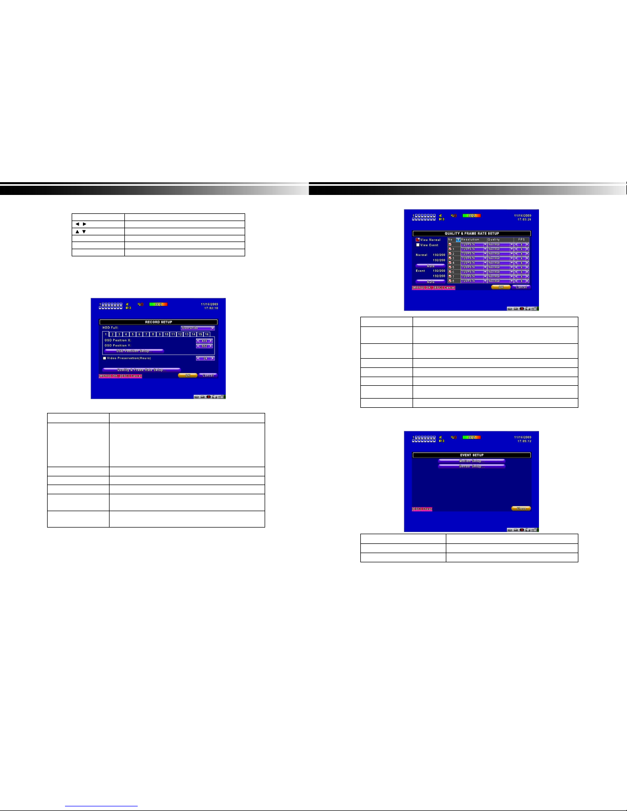
1-1 RECORD SETUP ____________________________________________5
1-1.1 Quality & Frame Rate Setup _____________________________6
1-2 EVENT SETUP______________________________________________6
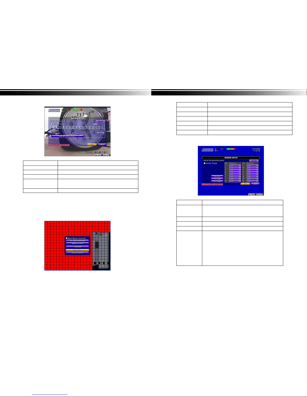
1-2.1 MOTION SETUP ________________________________________7
1-2.1.1 MOTION AREA SETUP______________________________7
1-2.2 SENSOR SETUP________________________________________8
1-3 SCHEDULE SETUP __________________________________________9
1-3.1 Schedule Record Setup _________________________________9
1-3.2 Holiday Setup_________________________________________10
1-4 CAMERA SETUP ___________________________________________10
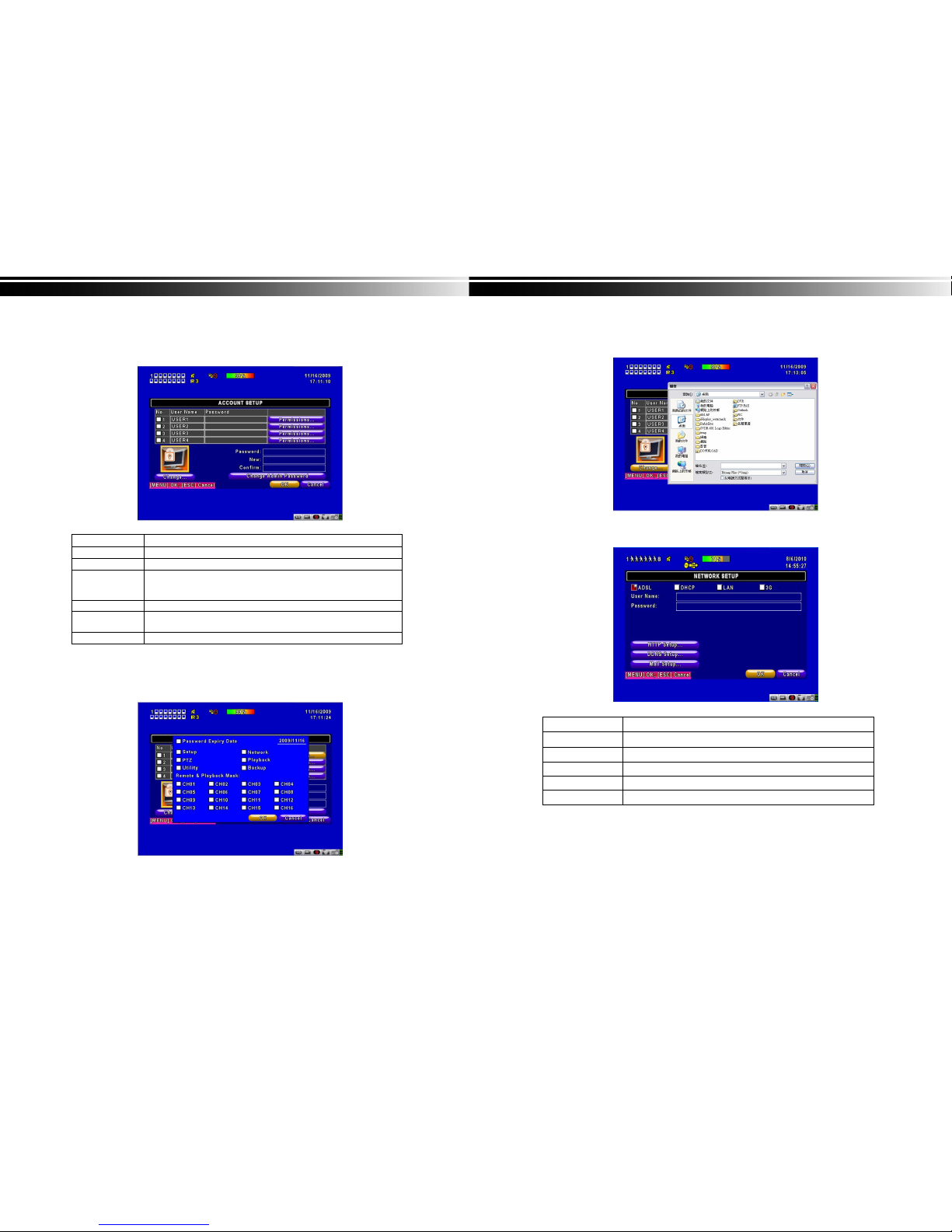
1-5 ACCOUNT SETUP __________________________________________11
1-5.1 Permission Setup______________________________________11
1-5.2 User Picture Setup ____________________________________12
1-6 NETWORKING SETUP_______________________________________12
1-6.1 NETWORKING SETUP__________________________________13
1-6.1.1 DHCP ___________________________________________13
1-6.1.2 LAN_____________________________________________13
1-6.1.3 ADSL ___________________________________________14
1-6.1.4 3G______________________________________________14
1-6.2 HTTP Setup___________________________________________15
1-6.3 DDNS Setup __________________________________________16
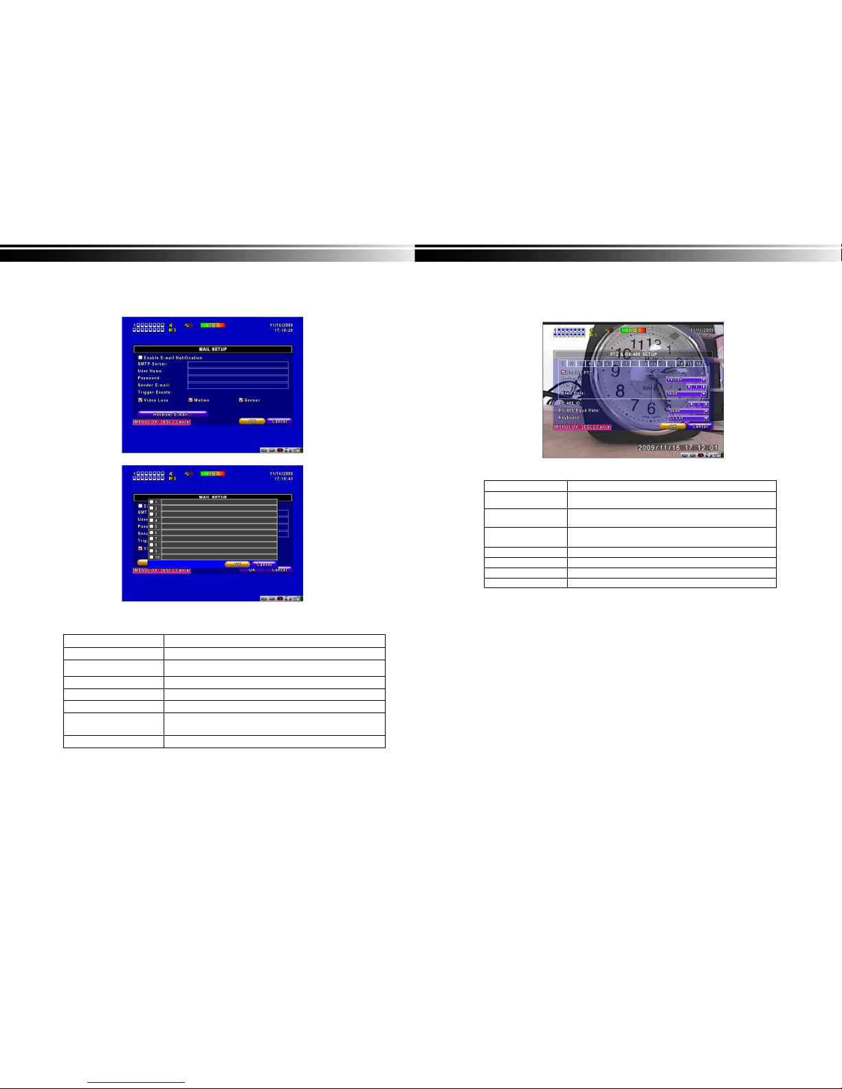
1-6.4 Mail Setup____________________________________________17
1-7 PTZ & RS485 SETUP _______________________________________18
1-8 SYSTEM SETUP____________________________________________19
1-8.1 DISPLAY SETUP_______________________________________19
1-8.2 DATE/TIME SETUP_____________________________________20
1-8.2.1 CHANGE DATE & TIME____________________________21
1-8.2.2 TIME ZONE AND DAYLIGHT SAVING TIME SETUP ____21
1-8.2.3 INTERNET TIME SETUP ___________________________22
1-8.3 BUZZER & RELAY SETUP ______________________________22
1-8.4 SPOT SETUP _________________________________________23
1-9 UTILITY SETUP ____________________________________________24
1-10 DIAGNOSTIC _____________________________________________25
CHAPTER 2 BACKUP & SEARCH___________________________________26
2-1 BACKUP SETUP ___________________________________________26
2-2 SEARCH SETUP ___________________________________________29
2-2.1 EVENT SEARCH_______________________________________29
2-2.1.1 CRITERIA SETUP FOR EVENT SEARCH______________30
2-2.2 TIME SEARCH ________________________________________31
CHAPTER 3 Remote Software Installation and Setup____________________32
3-1 Remote Software Installation and instruction___________________32
3-2 How to do remote monitoring through IE _____________________34
3-3 How to do remote monitoring through JPEG VIEWER(Only Monitor
Function) _____________________________________________________35
3-4 Remote Viewing Software Instructions ________________________37
4
CHAPTER 1 MAIN MENU SETUP
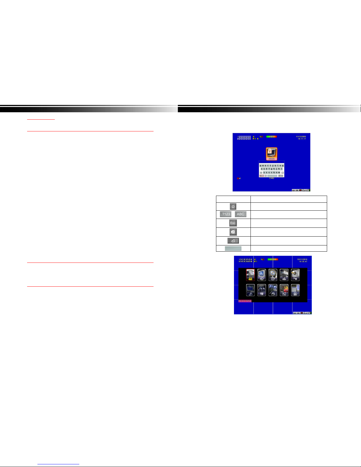
To enter the main menu and set up DVR, log-in account and user password are required.
The default password of the administrator is “123456”. Please check the “Account Setup” for
related setup of other log-in users.
Table 1-0.1 Some definition of virtual keyboard.
Item Description
Switch between capital and small letters.
/ Switch between numbers and letters.
Press to cancel the setup, and re-choose the login
account.
Delete the last character.
Enter to identify the password. It will enter the set
up menu, If the password is verified.
Space key

5
Table 1-0.2 The operation of remote control under the setting menu
Item Description
Switch to different options under one item
Switch to different items
MENU Save setup and back to LIVE mode
ESC Back to Upper level of menu without saving
ENTER Enter the menu, or display virtual keyboard
PS. The initialization of new-installed HD is required before recording, please refer to “ UTILITY
SETUP” for detail.
1-1 RECORD SETUP
Item Description
HDD FULL
Select STOP to stop recording or OVERWRITE to reuse the
HDD when HDD is full
「Stop」:Stop Recording
「Overwrite」:Start to overwrite that begin from the oldest data
of HDD, and continue to record.
OSD position X Setup OSD X axis
OSD position Y Set up OSD y axis
OSD position setup Set up OSD axis
Video Preservation Setup the video preservation period. Recorded video will be
deleted automatically after expiry of preservation period.
Quality & Frame Rate
Setup Setup the quality and frame rate for each channel under normal
recording and event recording type.
Note:4CH DVR will display 4 channels and 8CH DVR will display 8 channels.
6
1-1.1 Quality & Frame Rate Setup
Item Description
Normal setup/
event setup Select recording mode
Resolution Select recording resolution: NTSC:360x240, 720x240, 720x480
PAL:352X288,704X288,704X576
Record Type You can setup quality and FPS separately for record type.
No. Check/uncheck the box enable/disable selected channel recording
Quality Select quality: Below Basic/ Basic/ Normal/ High/ Highest
FPS Select recording frame rate.
(The number of sheets in accordance with the actual models)
Auto Assign each channel with itsmaximum accessible fps
Note:4CH DVR will display 4 channels and 8CH DVR will display 8 channels.
1-2 EVENT SETUP
Item Description
Motion Setup Enter to set up motion detection
Sensor Setup Enter to set up sensor detection

7
1-2.1 MOTION SETUP
Item Description
Alarm Duration(Seconds) When motion detect,the number of seconds continuous alarm
1~16 You can setup independently for each channel.
Enable Check the box to Enable/Disable motion detection for each channel.
Sensitivity Drag the white bar or press ◀▶to set up Sensitivity from a
Value of 0 to 10 for each channel. The higher value you set t
he more sensitive it will be.
Motion Area Setup Enter to setup motion detection area
Note:4CH DVR will display 4 channels and 8CH DVR will display 8 channels.
1-2.1.1 MOTION AREA SETUP
The motion detection has been divided into 22x18 grids. The default detection area is
full screen as it marked in transparent for local DVR and purple for remote access.
Areas deselected for motion detection are marked in red for both local and remote site.
8
Item Description
Mask Mouse Selection Switch between “select” and “deselect” for cursor-dragging function
All Area Detection Select entire screen as detection area.
Mask All Area Deselect entire detection area.
Continue Continue setup
Exit & Save Save setup and leave
Exit & Discard Cancel setup and leave
1-2.2 SENSOR SETUP
Item Description
Sensor Popup Check the box to Enable/Disable popup screen function for all
channels. When Sensor is detected in LIVE mode, the detected
channel image will pop up in full screen display.
All Off Set all sensor off
All Low Set all sensor polarity low
All High Set all sensor polarity high
Sensor Polarity Click or press ▼to select between HIGH, LOW voltage for
triggering sensor detection or OFF to turn off polarity for each
channel
Low Polarity:Sensor has not been triggered. When connected,
sensor will be turned on..
High Polarity:Sensor has been triggered. When connected, sensor
status will be turned off..
Off :Sensor is deactivated, and will not be turned on/off.
Note:4CHDVR will display 4 channels and 8CH DVR will display 8 channels.

9
1-3 SCHEDULE SETUP
Except from starting recording manually, you can also setup the recording time by weeks
and schedule including normal, motion detect, and recording type.
Item Description
Page Each page provides 10 schedules for setup. 5 pages in total.
Holiday Setup Enter to setup holiday, up to 50 days, other than weekends,.
View Event/ Motion/
Sensor Setup View Normal/ Motion/Sensor
Note:4CH DVR will display 4 channels and 8CH DVR will display 8 channels.
1-3.1 Schedule Record Setup
Click on the time on the left side. The setup menu will be displayed. You can have
detail setup by dates, Time and event.
10
1-3.2 Holiday Setup
Since holidays are different by different country and region, you can setup the holiday of
your location accordingly.
1-4 CAMERASETUP
Item Description
1~16 You can setup independently for each channel.
Mask Check the box to Enable/Disable mask function for LIVE mode
Sharpness Drag the bar or press ◀▶to adjust Sharpness of your camera from value 0 to 15.
Brightness
Drag the bar or press ◀▶to adjust Brightness of your camera from value 1 to 255.
Contrast Drag the bar or press ◀▶to adjust Contrast of your camera from value 1 to255.
Saturation Drag the bar or press ◀▶to adjust Saturation of your camera from value 1 to 255.
Name Set up name of each channel
Volume Audio volume under LIVE mode and recording mode can be adjusted.
Note:4CH DVR will display 4 channels and 8CH DVR will display 8 channels.

11
1-5 ACCOUNT SETUP
The Account Setup menu is used to provide role-based permission independently setting for
each user (maximum of 4 users) to access DVR over network. The default admin account and
password is “admin” and “123456”
(The default password remains the same after firmware upgrade)
Item Description
No. Check to activate the user’s account.
Username Set up user name
Password Set up a password for each user. Password is required to have 8
characters and can be a combination of letters and numbers and is
case sensitive.
Permissions Set up Permissions for each user
Change Admin
Password Change administrator’s password
Picture Change the user’s picture
1-5.1 Permission Setup
TheAccount Setup is set to provide individual user (maximum of 4 users) role-based
permissions, including access to Setup menu, Network operation, PTZ function, Playback,
Utility, Backup, Password expiry date and Mask on specific channels while playing back.
12
1-5.2 User Picture Setup
Users can upload a selected picture from a remote computer
1-6 NETWORKING SETUP
Item Description
Connect type Setup mode for network connection: (ADSL、DHCP、LAN、3G).
HTTPSetup Enter to set up HTTP
DDNS Setup Enter to set up DDNS
Mail Setup Enter to set up mail
3G Setup Enter to set up 3G network

13
1-6.1 NETWORKING SETUP
There are three ways to connect to the network as followed.
1-6.1.1 DHCP
When DHCP is selected, IP address will be assigned by DHCP server automatically.
1-6.1.2 LAN
Select LAN to manually input the network settings
Item Description
IPAddress Enter IP address provided by ISP
Subnet Mask Enter IP address of Subnet Mask provided by ISP
Gateway Enter IP address of Gate way provided by ISP
DNS Enter DNS address provided by ISP.
(Note: The correct DNS address must be entered for DDNS function).
14
1-6.1.3 ADSL
Select ADSL for network connection, the following information is required.
Item Description
User Name Enter user name provided by ISP
Password Enter password provided by ISP
1-6.1.4 3G
Select 3G for network connection, the following information is required.
Item Description
Dial-up Number Dial-up Number,Determined as the ISP
PIN Enter SIM card password
APN Enter ”internet”
Advance Setting The advanced settings (Taiwan ISP outside)

15
Item Description
Enable Enable advance setting
User Name Enter ISP username
Password Enter ISP password
IPAddress Enter the ISP provides a fixed IP address。
(if the client uses the Internet only need to enter a fixed IP)
PS:This feature currently only supports the Huawei 3G card
1-6.2 HTTP Setup
Item Description
Enable HTTP
Server Check to enable HTTP server. Users can remotely access into the
DVR over the network if the HTTP function is activated.
Port Enter a valid port value from 1 up to 65000. The default value is 80.
Auto Assign each channel with itsmaxima accessible fps
No. Channel number
Quality Set up remote view quality( below basic, basic, normal, high, highest
FPS Set up remote view FPS
16
1-6.3 DDNS Setup
Item Description
Enable DDNS Enable/disable DDNS function.
DDNS Server Enter the registered DDNS Server:
ez-dns*、I-DVR.NET*、DYNDNS.ORG、NO-IP.ORG、3322.ORG
Host Name Enter the completed registered SMTP Server.
(Including username + Server)
If the user name is h.264 and you choose i-dvr as your server,
you should enter: h.264.i-dvr.net
User Name Enter user name.
Password Enter password.
*For more detailed I-DVR.NET,ez-dns operation instruction,please refer to appendix

17
1-6.4 Mail Setup
When an event occurs (VLOSS, MOTION), an email will be sent to the receiver’s account
automatically. If you select Motion, you will be emailed a snapshot of the event.
Item Description
Enable E-mail Notification Check the box to enable/disable E-mail Notification function.
SMTP Server Enter to set up SMTP Server Address
User Name Enter to set up User Name.
Password Enter to set up Password.
Sender E-mail Enter to set up e-mail address of receivers.
Trigger Event Enter to select events to send out E-mail notifications when below
circumstances happen: Motion, Sensor andVloss (Video Loss).
Receiver E-mail Enter to set up e-mail addresses for up to 10 receivers individually.
18
1-7 PTZ & RS485 SETUP
The DVR allows users to control PTZ functions of your camera. To enable PTZ function,the 485
cable should be connected to the RS-485 port of DVR.
Item Description
Enable PTZ Click the box to Enable/Disable PTZ function for each channel.
Protocol Set up the protocol of PTZ cam. The supported protocols are
PELCO-P, PELCO-D, KND, LI-LIN, SAMSUNG, LG, AVTECH.
PTZ ID Click or press ◀▶to set up PTZ ID. The valid ID value is from 1
to 64.
Baud Rate Select Baud Rate for PTZ from 2400, 4800, 9600,19200
RS-485 ID Select RS-485 ID from 1 to 64
RS-485 Baud Rate Select RS-485 Baud Rate from 2400. 4800, 9600,19200
Keyboard Select Keyboard.
Note:4CH DVR will display 4 channels. 8CH DVR will display 8 channels.

19
1-8 SYSTEM SETUP
Item Description
DVR Name The name of DVR will be shown when users login from remote access.
DVR Location The location of DVR will be shown when users login fromremote access
Language Click or press ▼to select OSD language.
Remote ID Default ID is 0. DVR is controlled by standard remote control,
Display Setup Enter to set up Display
Date/Time Setup Enter to set up Date/Time
Device Setup Enter to set up Buzzer & Relay
Spot Setup Enter to set up Spot
1-8.1 DISPLAY SETUP
20
Item Description
Auto-Seq Interval Set up duration time in seconds for the interval between channels
under Auto-Seq mode.
Show OSD Turn On / Off OSD display
Show DVR Status Turn On / Off DVR illustration and record status display
Show Date/Time Turn On / Off date and time display
Show Channel Name Turn On / Off channel name display
Border Color Set up the color of border in LIVE , PLAYBACK mode.(Red,
Green, Blue)
1-8.2 DATE/TIME SETUP
Item Description
Hour Format 12HOURS/ 24HOURS
Date Format MM-DD-YY/DD-MM-YY/YY-MM-DD
Date/Time Position Choose the position of Time and Date display
Change Date & Time Setup time and date of DVR
Time Zone Setup Set up GMT and Daylight Saving Time.
Internet Time Setup Setup automatic synchronization with internet server

21
1-8.2.1 CHANGE DATE & TIME
Setup date and time of DVR manually according to user’s local time.
1-8.2.2 TIME ZONE AND DAYLIGHT SAVING TIME SETUP
Set up time zone and activate Daylight Saving Time function according to user’s DVR location.
Item Description
Select Time Zone Enter to modify GMT from GMT- 13 to GMT+ 13
Daylight Saving Time Turn on/ off Daylight Saving Time
22
1-8.2.3 INTERNET TIME SETUP
Synchronize your DVR time with internet time server.
Item Description
Automatic
Synchronization
Check to enable DVR automatic synchronization function.
Effective by this option selected, DVR will automatically
synchronize the time upon rebooting or by every 24 hours after
booting.
Update Now Synchronize with the NTP server immediately
1-8.3 BUZZER & RELAY SETUP
Item Description
Mouse Speed Select the mouse cursor speed, the further to the right the faster
the mouse will move
Buzzer & Relay Setup Into the buzzer & relay setup.

23
Item Description
Key Tone Enable/Disable Audible button presses for remote and panel
Buzzer Enable/Disable buzzer operation when the alarm is triggered for
sensor, motion and vloss (Video Loss).
Relay Enable/Disable the signal to be sent to the RELAY OUT blocks
when the alarm is triggered for sensor, motion and vloss.
1-8.4 SPOT SETUP
Main monitor output is enabled by default out of the BNC composite output and is
selectable to be a Spot Monitor output
Item Description
SPOT MODE Channels display in spot for two different modes:
Disable: The screen is same the main screen with VGA output,
Enable: Spot Mode
Interval (Seconds) The duration time in seconds for the interval between channels
under SPOT mode.
Skip Video Loss Channel Whether to skip channels without video signal.
24
1-9 UTILITY SETUP
Item Description
HDD Initialization Select to enter hard disk initialization menu. Please stop
recording before entering this menu. Enter the menu,
system will show all the data (model, volume) of HDD that
installed in DVR. Check the HDD you’d like to initialize
then press “Start”. HDD initialization is successful when
the status shows “Succeed”
USB Initialization Clean up all data on USB. Enter USB initialization and
press YES to clean up all data on your USB. The
initialization is done when it’s showed “Succeed”.
System Recovery Restore DVR to factory Defaults
Reset System Events Reset the event list
Copy Setup to USB Copy configuration to a USB device. There will be a file
named 「sdvr_conf.dat」on your USB.
Download Setup from USB Download configuration from a USB device into DVR.
Upgrade Upgrade DVR through USB.
Please stop recording and backup setup configuration
before upgrading.
System will reboot automatically when the upgrade is
completed.
Notice! DO NOT TURN OFF POWER OR UNPLUG USB DEVICE DURING THE UPGRADE
as it may cause incomplete firmware upgrade and damage to the DVR.

25
1-10 DIAGNOSTIC
Item Description
Version The current firmware version of DVR
IP The connected IP address of DVR. If disconnected from
network, the screen will display
” NETWORK DISCONNECT”.
MAC MAC Address of DVR
No. HDD number
Volume HDD Capacity
Used Rate Percentage of space used on HDD.
Status
Shows HDD status.
USING: means the HDD is being used for recording now
GOOD/BAD: means the HDD has a known/unknown
format for the DVR. (Note: Please initialize your
newly-installed HDDbefore using it.)
HDD Status
Format Time The latest format time of HDD
26
CHAPTER 2 BACKUP & SEARCH
2-1 BACKUP SETUP
User can backup any segment of recorded datain a specified time frame. To do so, either a CD
R/W or storage device, like USB, must be connected to the DVR. The format of backup file is
IRF file that can be played by both “Ifileplay” and “CMS”
*:Use the USB flash backup, the system will automatically copy "Ifileplay" to the USB
Item Description
From The start time ofbackup file
To The end time of backup file
Device Select CD/DVD, USB or PC as the backup device
Free Space The available space in your backup device. (not available for PC backup)
Refresh Recalculate the available space of backup device. (not available for PC backup)
Required Space Show the size of the backup file
Calculate Calculate the size of backup file
Start Start backup operation.
Be sure to calculate the size of backup file BEFORE operating backup.
Note! Do not unplug the USB device or turn off the DVR during the backup process to
avoid unrecoverable error.

27
iFileplay Instructions
Step 1: install「iFileplay」software to your PC. You can get「iFileplay」file fromthe CD with DVR
Contents
PS: When you using USB to backup file, iFileplay.exe will copy to USB with the backup
file automatically.
Step 2:Run「ifileplaypack.exe」。
Step 3:Click「open」,select the DVR backup file。
28
Step 4:Ifileplay software will play the irf file automatically.
Step 5:Ifthere is no display on the screen, the backed up file is not our DVR recording format.
Please check it.

29
2-2 SEARCH SETUP
Item Description
Event Search Event search menu
Time Search Enter time search menu
2-2.1 EVENT SEARCH
The DVR automatically records events with type, time and channel information included. If there
is recording data for an event, a yellow signal will be shown on the left side of time
information. Rest your cursor under the line and press “enter”, or left click your mouse to
playback the recording data.
P.S. Event Records will still be generated even when hard disk is not installed or the
record function is not activated. However, the data can’t be viewed after selecting it.
30
Item Description
Criteria Setup conditions of event search
Page Switch between pages of events
Date/Time Date/time when event occurred.
Event type, defined as following
MOTION Motion Detected
Video Loss Video Loss
Remote Login user log-in over the network
Remote Logout user log-out over the network
Power On DVR Power on
HDD Full HDD Space FULL
HDD Error Detect HDD error
Event Type
Reboot DVR Reboot
Info The channel where event occurs or login user
2-2.1.1 CRITERIA SETUP FOR EVENT SEARCH
The amount of events can be numerous. Therefore, you can facilitate event sorting by setting
up “criteria”. Setup “start time” and “end time” for event search, then the search result will be
limited to this specific period of time. Only checked events and channels will be sorted in event
search.

31
2-2.2 TIME SEARCH
TIME SEARCH can search for the specific time of recording data to playback. Press “Enter” or
left click on the desired date to playback. Note that dates with recording data are marked with a
red square “ □“System will start playing back according to the date you selected. Calendar
will be shown by using mouse to click on “year” and “month”.
Click “date” to display recorded time of that specific date with the time bar. You can change time
(hour/minute/second) or click on a specific time of time bar by mouse then press “ok”. DVR will
playback the selected recorded data.
32
CHAPTER 3 Remote Software Installation and Setup
3-1 Remote Software Installation and instruction
Remote software:「DVR Remote Desktop」can allow you to remotely access and control the
DVR from a PC or Mac .
p.s. Operation system currently supports Windows XP SP2(above) and Windows
Vista, Windows 7, and Mac OSX 10.6 or above
Step One:Enter the IP address of DVR in internet browser
Step Two: Windows as below will show up. Please enter the user name and password. Default
user name and password is admin/123456. Other related setup about user account
and password, please check “4-5 Account Setup. “
Step Three: Click on the link to start downloading the Remote software.

33
Step Four: Run or Save our remote software.
Step Five: If you choose to run the software, Start window will be shown up. Please enter
information of login DVR: IP, Port, Username and Password, or choose “Play
Recorded File” to open backup files in your PC.
Step Six: You’ve logged into the DVR
34
3-2 How to do remote monitoring through IE
Step One:Enter the IP address of DVR in IE browser. The address appeared in this image is
only for demonstration.Actual address isdepending on the setup of on-site DVR.
Step Two: Windows as below will show up. Please enter the user name and password. Default
user name and password is admin/123456. Other related setup about user account
and password, please check “4-5 Account Setup. “ The user name and password
appeared in this image is only for demonstration. Actual user name and password
will depend on the setup of the on-site DVR.
Step Three: Click on “Internet Explorer 6, 7, and 8”to start downloading the software. ( The first
option is for IE view, please refer to next chapter for more information)
p.s. There will be IE connection security issue when clicking this link for the first time.
Please refer to index II for Remote Monitoring IE ActiveX Control Installation Instruction.

35
Step Four: DVR images appear.
3-3 How to do remote monitoring through JPEG VIEWER(Only Monitor Fun
ction)
Step One:Enter the IP address of DVR in IE browser. The address appeared in this image is
only for demonstration.Actual address isdepending on the setup of on-site DVR.
Step Two: Windows as below will show up. Please enter the user name and password. Default
user name and password is admin/123456. Other related setup about user account
and password, please check “4-5 Account Setup. “ The user name and password
appeared in this image is only for demonstration. Actual user name and password
depend on the setup of on-site DVR.
36
Step Three: Click on “Jpeg Viewer”
Step Four: DVR images appear.
PS : Only for live viewing, no control functions.

37
3-4 Remote Software Operation
Open the file “DVRemoteDesktop.exe”; enter the information of DVR “IP address”, “Port”
“Username” and “Password” and click “OK”. You should be able to login DVR successfully and
start touse the software. The default username and password is 「admin/ 123456」
“DVRemoteDesktop.exe” Remote software provides some extra functions for remote users.
Please check Table 3-4.1 for minimum system requirements for “DVRemoteDesktop.exe”
operation.
Table 3-4.1 System Requirements forAP software
CPU Intel Pentium 4 above
OS Microsoft Windows 7、Windows Vista、Windows XP SP2 above
RAM 512M above
VGA Card Needed to support DirectX9.0c (Above) Note 1
Others DirectX 9.0c or above
Note 1:
Known VGA card that support DirectX9.0 currently:
NVIDIA: Geforce FXseries, Geforce 6series, Geforce 7series, Geforce 8series, Geforce
9series, Geforce 200series, etc.
Or
visit:http://en.wikipedia.org/wiki/Comparison_of_Nvidia_graphics_processing_units
ATI: Radeon R300series, Radeon R400series, Radeon R500series, Radeon R600series,
Radeon R700series, Radeon HD 3xxx IGPseries, Mobility Radeonseries (9500
above), Mobility Radeon Xseries, Mobility Radeon HDseries, or FireGLVseries etc.
Or visit: http://en.wikipedia.org/wiki/Comparison_of_ATI_graphics_processing_units
SiS: SiS 67Xseries, or SiS 77Xseries etc.
Or visit: http://www.sis.com/support/support_compare.htm
Intel: 91Xseries, 94Xseries, 96Xseries, G3Xseries, orG4Xseries, etc.
Or visit: http://en.wikipedia.org/wiki/Intel_GMA
This manual suits for next models
2
Table of contents
Other GOLDEN STATE INSTRUMENT DVR manuals