Goldenman Petroleum Equipment XQ140/30-SM User manual

Goldenman Petroleum Equipment Co., Ltd
CONTENTS
1. Safety Guide
2. Overview
3. Technical Parameters
4. Installation
5. Setting up
6. Operation instructions
7. Maintenance and Lubrication
8. Storing and Shipping
9. Troubleshooting
Annexed table 1: Spare parts list
Annexed table 2: Recommended spares for one year

Goldenman Petroleum Equipment Co., Ltd
Warning
XQ140/30 tubing power tong is a kind of high mechanical torque wrench. To ensure safety,
operator should follow the safety information described in this manual.
1.
Safety Information
1.1
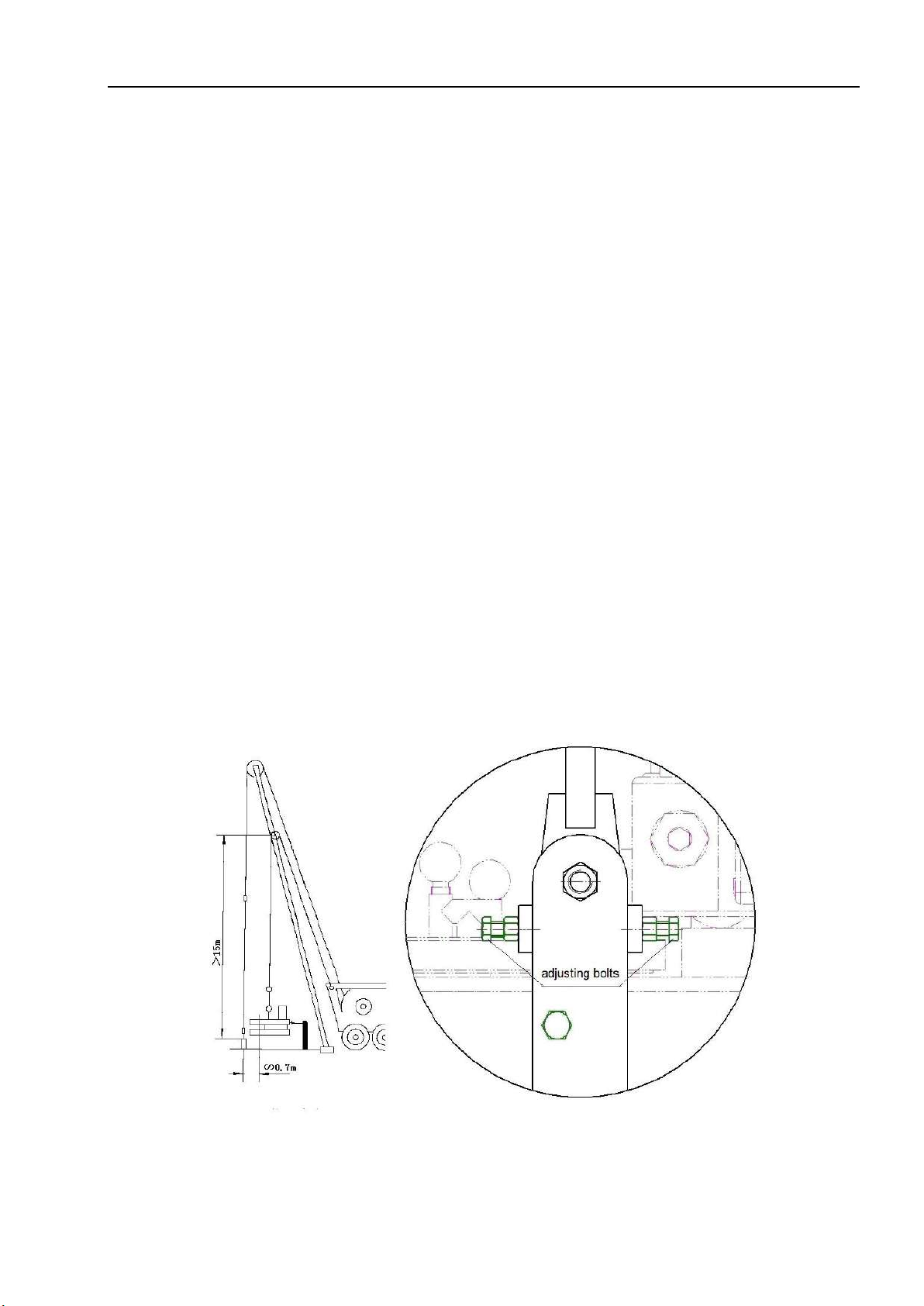
Hanging of power tong
Use a wire rope not less than 1/2in (dia.) as hanging and fixing rope.
Warning: Prior to hang the tong, check wire rope, pulley, shackle and other attachments if worn or
damaged, if well maintained, and lock device if effective. It will cause serious damage on man and
rig equipment in the process of handing the power tong if failure of hanging happens.
1.2
Fixing of safety rope
Use a wire rope not less than 5/8in(dia.) to connect the tong tail, as safety rope.
Warning: During working, the tong tail part is easy to impact. It is necessary to attach a safety rope
against sliding of backup tong. Bearing connecting, check the rope and its attachments such as
shackles for worn and damage, and check lock device if effective. Failure of wire rope in the
process of handling the power tong will cause severe personal injury and equipment damage.
1.3
Connecting of hydraulic hoses
Warning: Ensure joints completely sealed. Improper maintenance and operation may cause leaking
of hoses, which will cause environmental pollution. Operators should be familiar with the operation
procedures and
1.4
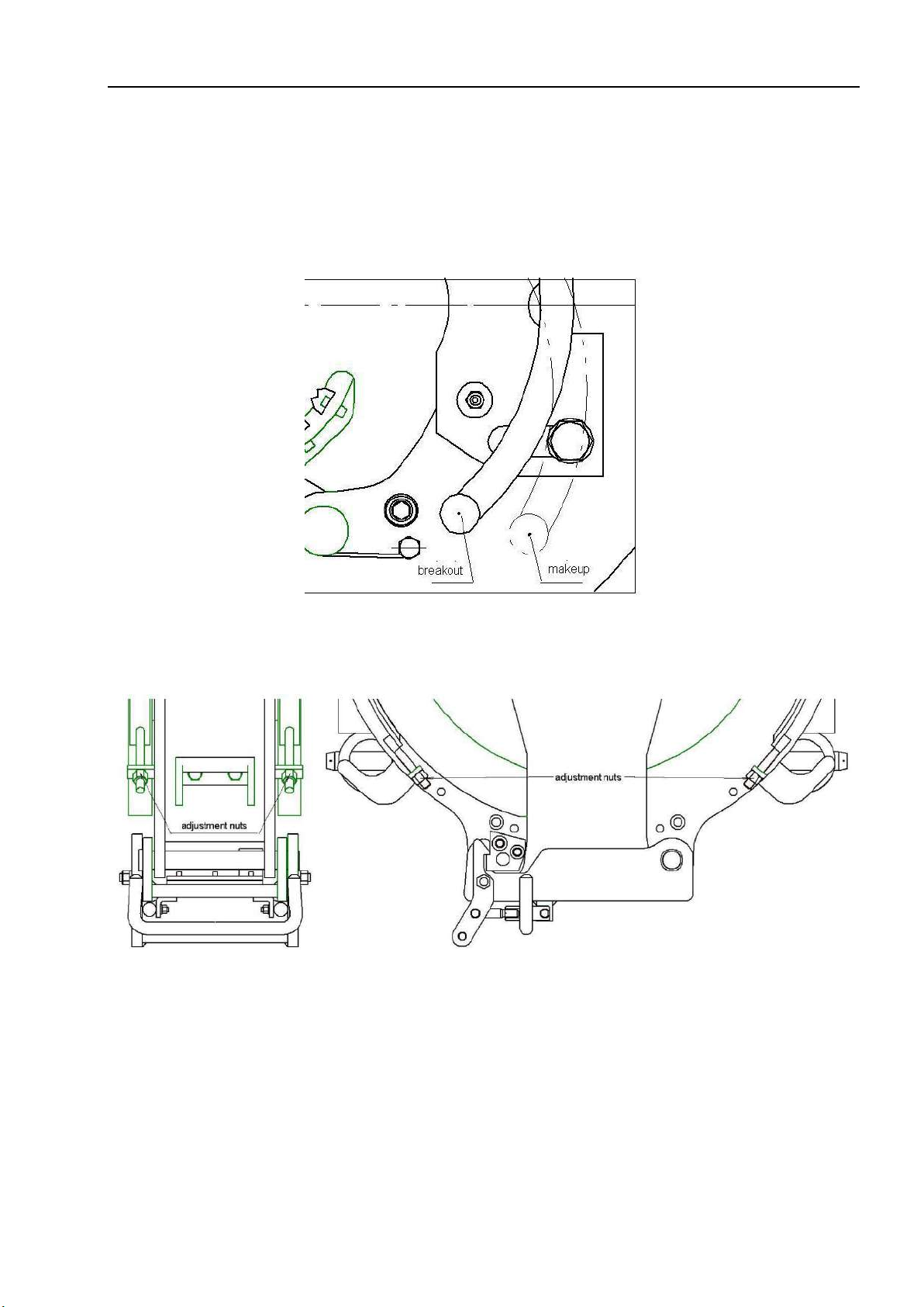
Operating of power tong
Warning: Avoid any part of human body or clothes near the rotating area of the power tong.
Operator and other people should keep away from tong tail power direction to prevent personal
injury and equipment damage.
Warning: Do remember to shut off power unit when replacing jaws of the power tong.
Warning: Never allow to operate the tong when the tong door is open.
Warning: Do not put the tong operation handle at the same location under any situation, or the tong
will fail to control.
1.5
Others
Warning: Do not adjust, maintain, dismantle or lubricate the power tong when the power unit is n.
Warning: Hydraulic hose and seal rings for replacing should be proof pressure tested under 21MPa
(3000psi).
Warning: Remember to use genuine parts manufactured by Goldenman Company.
2.
Overview
As one kind of open throat power tong used for making up and breaking out pips in the well

Goldenman Petroleum Equipment Co., Ltd
workover operation in oil field, XQ140/30 tubing power tong is applicable to tubing, small drill
pipe or small casing within the scope of 60-140mm. It is applicable to both land and offshore
oilfields. Featured by simple structure, convenient operation, broad range of application and large
output torque, it can reduce the labor strength of oil field and improve the working efficiency and
workover quality.
3.
Technical Parameters
3.1
Scope of application
3.2
Rated power supply pressure
60-140mm (23/8-51/2”)
20Mpa
3.3 Working flow
120-160L/min
3.4 Maximum high-gear torque
4740 N. m
3.5 Maximum low-gear torque
30 kN. m
3.6 High-gear speed
34-45 rpm
3.7 Low-gear speed
8-10.5 rpm
3.8 Weight
860 kg
3.9 Overall dimensions of combined tong
1180×1000×1 680mm
4.
Installation
4.1
Suspension
Connect spring hanger (or lifting hydraulic cylinder) with hanging rod of master tong and hoist the
tubing power tong on the derrick of workover rig. The suspension point shall be more than 15m
from the wellhead. The center of tong head should be about 0.7m far away from wellhead under
free suspension state. The suspension height is proper if the back-up tong just can grip tool joint or
the coupling of tubing or casing. Refer to Fig.1.
Fig.1 Installation over wellhead Fig.2 Balance Adjustment
4.2
Leveling

Goldenman Petroleum Equipment Co., Ltd
Adjust the adjusting screw on the hanger rod to make the tubing power tong always horizontal.
Clamping will be a failure if the tubing power tong is not kept horizontal. Refer to Fig.2.
4.3
Installation of sensor
Refer to Fig. 3 for installation of sensor according to working status of makeup or breakout.
Fig.3 Location of the sensor Fig.4 Local view of Tong foots
4.4
Installation of jaw plate
Select proper jaws based on the pipe to handle. During the installation, always make sure the
opening of brake disc and notched gear is consistent. In this way, the pulling rod is at the back side,
which will facilitate the installation of jaws. Pay attention to the right and left direction during the
installation process, refer to Fig.5. Add lubricating grease to jaw pins and fix them with cotter pins.
Refer to Table 1 for jaw specification details.
4.5
Connection of hydraulic pipeline
Prior to starting the hydraulic power station, connect the high pressure hose and oil return hose to
the power tong and hydraulic power unit.
4.6
Additional information
It is necessary to remove front tong feet before operating the tong, and loosen the nuts below the
connection. Refer to Fig.4.
Table 1: Jaw Specification of the Tong

Goldenman Petroleum Equipmen
t Co., Ltd
No.
Part No.
Description
No.
Part No.
Description
1
RS201.187.00AL/R
23/8 jaw left/ right
5
RS201.186.00AL/R
41/2 jaw left/right
2
RS201.184.00AL/R
27/8 jaw left/ right
6
RS201.181.00AL/R
5 jaw left/right
3
RS201.182.00AL/R
31/2 jaw left/ right
7
RS201.183.00AL/R
51/2 jaw left/right
4
RS201.185.00AL/R
4 jaw left/ right
8
RS202.189.00A
6.05 jaw backup
Fig. 5 Left and right jaws Fig.6 Two Position Tee Valve
5.
Setting up
5.1
Torque
Torque control on tubing power tong XQ140/30 includes manual control and automatic control.
Manual control is to set the red pointer on torque meter to required value. Then operate multi-way
valve handle to take torque value to this point and then back to middle position. Tong head stops
working. Automatic control is to connect tension sensor and solenoid valve of power unit with the
computer. Preset required torque value in the computer. It tong torque is up to required value, the
computer it will control the power unit to unload. So the tong head stops working.
5.2
Pressure of backup tong
5.2.1
Hydraulic system of backup tong includes one pressure reducing valve and one increasing
valve. Firstly reduce pressure to 10MPa, the increase pressure via the increasing valve. Refer to
Fig.7 for pressure reducing valve. Loosen lock nut and adjust the screw, you can control pressure of
backup tong.
5.2.2
Operate the multi-way valve handle for backup tong, from the pressure gauge of backup tong
you can see the cylinder pressure value is on the increase. Release the valve handle, pressure will
not change anymore and remain unchanged.

Goldenman Petroleum Equipment Co.,Ltd
5.2.3
Pressure setup of backup tong depends on pipe size and thickness, and actual torque needs for
makeup and breakout, ranging from 2 MPa to 40 MPa.
6.
Operation Procedure
6.1
Put two-position tee valve to the side of suspension cylinder, then push left handle of
combination valve forward to raise the tong up and align against tubing coupling. Refer to Fig.6. If
need to adjust a little downwards, operate the manual valve on the combination valve, refer to
Fig.12. Warning: Never to operate the combination valve handle.
6.2
Control of combination Valve

Goldenman Petroleum Equipment Co.,Ltd
The left handle of combination valve of this power tong can control the positive and negative
rotation of tong head, while the right handle can control the cylinder of back-up tong to clamp or
release, and the suspension cylinder to lift.
6.3
Adjust the nut at one end of brake band to make brake band tighten brake disc, refer to Fig.10.
6.4
Turn shifting lever assembly to its required position, makeup or breakout. Refer to Fig.9.
Fig. 9 Shifting Lever Position of Main Tong for Makeup/Breakout
Fig.10 Adjustment of Brake Band
6.5
Operate the right and left handles of combination valve, to open the openings of the main tong
head and back-up tong respectively.
6.6
Push forward the power tong and entangle pipe column with tong head. The pipe column should
be in the middle of jaws.
6.7
Close the main tong door.

Goldenman Petroleum Equipment Co.,Ltd
6.8
Operate right handle of the combination valve, to make back-up tong clamp pipe column. Refer
to Fig.8 for its gripping torque.
6.9
Operate left handle of the combination valve to clamp/release the pipe column, and then rotate
tong head reversely to move jaws apart from pipe.
6.10
Open the main tong door, and move power tong from pipe.
6.11
Shut down the power unit.
7.
Maintenance and Lubrication
7.1
Prior to job each day, check if all tightening screws are loose and fasten them if necessary.
7.2
Prior to job each day, add sufficient lubricating greases to all transmission parts, refer to Fig.11.
7.3
Check the tong after each time use. Remove water or sludge timely (if any).
7.4
Replace brake band when its thickness is below 8mm (original 10mm) after worn.
7.5
Clean the tong with diesel oil after completion for one well and coat grease on all rotation parts
after cleaning.
7.6
Never allow to clean the tong with steam to avoid damaging bearings due to oil-lacking and
water invasion.
7.7
Hydraulic oil temp shall be no over 65℃since being overheat will make the sealing of
hydraulic system invalid.
7.8
Always make hydraulic oil clean and ensure the oil filter can work normally. Change oil
immediately once it becomes dirty.
7.9
Selection of hydraulic oil:
7.9.1
YC-N46 low-freezing hydraulic oil, which is applicable to -20℃~+50℃;
7.9.2
YB-N46 anti-wearing hydraulic oil, which is applicable to -10℃~+50℃;
7.9.3
YA-N46common hydraulic oil, which is applicable to 0℃~+50℃。

Goldenman Petroleum Equipment Co.,Ltd
Fig. 11 Grease Points

Goldenman Petroleum Equipment Co.,Ltd
7.10
Table 2 Lubrication (grease)
No.
Points to grease
Tool
Frequency
Qty., grease points
1
Door lock
Brush
Once a day
1
2
Brake band
Brush
Once a day
2
3
Gear box
Grease gun
100g/week
1
4
Handles, high and low gear
Brush
Once a week
1
5
Operating lever
Brush
Once a week
2
6
Sensor shaft
Brush
Twice a week
2
7
Pin 插销
Brush
Once a day
4*2(master, backup)
8
Bearings, for rollers on upper and
lower tracks of notched gear
Brush
Once a day
2
9
Gear shaft
Grease gun
Twice a week
3
8.
Storing and shipping
Do avoid bumping during storing and shipping the power tong. Cover the tong with plastic bag and store it in
dry and ventilating place.
9.
Common Faults and Troubleshooting (Table 3)
Common faults
Cause
Troubleshooting
Tong die slips
The tong die groove is filled with
solid articles
Remove the foreign matters in tong
die groove
Tong die is worn too seriously
Change new tong die
The tong is not horizontal
Level the tong (master tong and back
tong)
The head of master tong fails to
align opening.
The stop pin is not included by reset
knob
Reset after switching reset knob
The power tong can not
generate sufficient torque
The pressure set is too low
Improve the pressure to the rate one
Valve is blocked
Check if the valve contains dirt and
clean the valve
Valve leaks
Check if oil seal or oil rod is blocked
Oil motor is worn
Repair or change the worn parts
The tong head rotates slowly
The flow of power unit is too low.
Increase pump flow
Insufficient oil in oil tank
Refueling
Too low or high oil viscosity
Change oil
Backup tong can not pressurize.
Pressure increasing valve is out of
function.
Replace the valve.
Check valve fails to open.
Replace the valve.
No torque show or torque value
shows incorrect.
Mounting position for tension sensor
is not correct.
Refer to Fig.3 for correction position.
Connection rod on the other side is
not installed.
Install the link.
Bushing is not installed at connection
site of the sensor.
Install the bushing.

Goldenman Petroleum Equipment Co.,Ltd
Annexed table 1 Spare Parts List (Table 5)
No.
Part No.
Description
Qty.
No.
Part No.
Description
Qty.
1
RS201.100-04
Left torsion spring
2
11
RS201.110-07
Pin 20*185
4
2
RS201.100-05
Right torsion spring
2
12
RS201.124-01
Thrust ring
1
3
RS201.110-02
Cam
3
13
JB/T7940.1
Grease fitting M10*1
1
4
RS201.140-03
Spring
2
14
JB/T7940.2
Grease fitting
45°M10*1
3
5
RS201.160.00
Brake band body
2
15
RS201.111.00
Left roller rack
1
6
RS201.170-05
Pinion
1
16
RS201.114.00
Left roller rack
1
7
RS201.181-02
Die
100
17
SCE2620
Needle bearing
1
8
JB/T7940.1
Grease fitting M8*1
2
18
RLM2225
Needle bearing
3
9
RS201.200-05A
Spring
2
19
Filter elementφ30*H32
1
10
RS201.110-06
Pin 20*220
2
Annexed table 2 Recommended spares for one year(Table 6)
N
o.
Part No.
Description
Qty.
No.
Part No.
Description
Qt
y.
1
RS201.100-04
Left torsion spring
2
9
RS201.110-06
Pin 20*220
2
2
RS201.100-05
Right torsion spring
2
10
RS201.110-07
Pin 20*185
4
3
RS201.140-03
Spring
2
11
RS201.124-01
Thrust ring
1
4
RS201.160.00
Brake band body
2
12
JB/T7940.1
Grease fitting M10*1
1
5
RS201.170-05
Pinion
1
13
JB/T7940.2
Grease fitting 45°M10*1
3
6
RS201.181-02
Die
1000
14
RLM2225
Needle bearing
3
7
JB/T7940.1
Grease fitting M8*1
2
15
SCE2620
Needle bearing
1
8
RS201.200-05A
Spring
16
Filter elementφ30*H32
2
Fig.12 Adjustment Valve for Lowering Suspension Cylinder

Goldenman Petroleum Equipment Co.,Ltd
Fig.13 Outline of XQ140/30 Tubing Tong

Goldenman Petroleum Equipment Co.,Ltd
Table 7 Parts Lists, Master Tong (See Fig.14)
No.
Part No.
Description
Qty
.
No.
Part No.
Description
Qty.
1
RS202.150.00A
Brake band
2
34
GB/T93
Washer 8
4
2
GB/T6170
Nut 10
4
35
RS201.100-03
Retainer plate
4
3
GB/T70.1
Screw M12*35
8
36
RS201.100-02
Small pillar
4
4
GB/T93
Washer 12
8
37
RS202.130-01A
Top face plate
1
5
GB/T119.1
Pin 12*50
4
38
GB/T70.1
Screw M10*25
27
6
RS202.110-02
Brake disc
2
39
GB/T93
Washer 10
29
7
GB/T70.1
Screw M10*30
4
40
GB/T119.1
Pin 10*25
12
8
GB/T93
Washer 10
4
41
GB/T810
Round nut M30*1.5
16
9
GB/T119.1
Pin 16*35
2
42
RS201.122-03
Pin Φ12*25
16
10
RS201.140-07
Upper door support lump
1
43
GB/T119.1
Pin 4*16
16
11
JB/T7940.4
Grease fitting 8
36
44
RNA22/8.2RS
Support roller
Φ12*Φ24*11.8
16
12
RS202.121-01
Guide roller shaft
36
45
RS202.122-01
Small roller support
16
13
NUTR17
Support roller
72
46
NATV15PP
Support roller
Φ15*Φ35*19
16
14
GB/T93
Washer 16
36
47
RS201.122-02
Pin Φ15*40
16
15
GB/T6170
Nut M16
36
48
RS202.110-04
Locating block
1
16
RS201.110-06
Pin 20*220
2
49
RS201.100-05
Right torsion spring
1
17
RS201.100-04
Left torsion spring
1
50
RS201.114-03
Roller Ⅱ
2
18
RS201.110-07
Pin 20*185
2
51
RS201.114-02
Pin 30*46
2
19
24.130-04
Safety pin 2*20*65
10
52
RS201.114-01
Right roller rack
1
20
RS201.111-01
Left roller rack
1
53
RS202.110-03
Jaw rack
1
21
GB/T879.1
Pin 5*40
3
54
GB/T 70.1
Screw M12*55
3
22
RS201.111-03
Pin 30*60
1
55
GB/T70.1
Screw M12*65
3
23
RS201.111-02
Roller I
1
56
GB/T119.1
Pin 销20*20
3
24
JB/T7940.1
Grease fitting M8*1
3
57
25
GB/T93
Washer 12
6
58
RS202.131.00
Side plate
1
26
GB/T93
Washer 8
3
59
GB/T70.1
Screw M10*25
10
27
GB/T70.1
Screw M8*40
3
60
RS203.132.00
Handle
5
28
RS201.110-02
Cam
3
61
Motor gearbox assy. See Fig.18
29
RS201.110-01
Notched gear
1
62
Dual gear assy. See Fig.20
30
RS201.140-08
Lower door support lump
1
63
Idle gear assy. See Fig.19
31
RS201.140-09
Copper sleeve
2
64
RS202.130-02
Bottom face plate
1
32
Makeup/breakout handle assy. See Fig. 15
65
RS202.170.00
Fixture support
1
33
GB/T5782
Bolt M8*45
4
66
GB/T70.1
Screw M10*40
2

Goldenman Petroleum Equipment Co.,Ltd
Fig.14 Master Tong

Operating Instruction of XQ140/30 Tubing Power Tong
Fig.15 Makeup/breakout Handle Assembly
Table 8 Parts List of Makeup/breakout Handle Assy.(Fig.15)
No.
Part No.
Description
Qty.
No.
Part No.
Description
Qty.
32.1
RS203.110-07
Handle
1
32.5
RS201.110-04
Washer
1
32.2
RS201.113.00
Shifting lever assy.
1
32.6
GB/T93
Washer 12
1
32.3
RS26.100-14
Spring 1.2*8*25
1
32.7
GB/T6170
Nut M12
1
32.4
GB/T308
Steel ball 10
1
Table 9 Parts List, Door Assembly (Fig.16)
No.
Part No.
Description
Qty.
No.
Part No.
Description
Qty.
1
GB/T5782
Bolt M6*40
2
8
GB/T6184
Nut M10
2
2
GB/T95
Washer 6
12
9
GB/T5782
Bolt M6*30
2
3
RS201.142.00
Door hook
1
10
RS201.140-06
Door pin
1
4
GB/T6184
Nut M6
4
11
RS201.140-10
Stud M10*240
1
5
RS201.140-01
Pin
2
12
RS201.141.00
Door
1
6
RS201.140-03
Spring
2
13
GB/T91
Cotter pin 5*45
1
7
GB/T95
Washer 10
2
Table 10 Parts List, Hanger Assembly (Fig.17)
No.
Part No.
Description
Qty.
No.
Part No.
Description
Qty.
1
RS202.141.00A
Hanger rod
1
6
GB/T5781
Bolt M16*35
4
2
GB/T6170
Nut M20
2
7
GB/T93
Washer 16
4
3
GB/T31.1
Bolt M20*75
2
8
RS201.150-01
Bolt
4
4
GB/T91
Pin 4*30
2
9
GB/T6170
Nut M12
4
5
RS201.153.00
Left seat
1
10
RS202.142.00A
Right seat
1

Operating Instruction of XQ140/30 Tubing Power Tong
Fig.16 Door Assembly
Fig.17 Hanger Assembly

Operating Instruction of XQ140/30 Tubing Power Tong
Table 11 Parts List, Motor Gearbox Assy.(Fig.18)
No.
Part No.
Description
Qty.
No.
Part No.
Description
Qty.
1
RS201.300-07
Flange
1
26
RS201.170-06
Dual gear
1
2
HM76-F200J1
Gear motor
1
27
RS201.170-05
Pinion
1
3
RS201.300-03
Flange
1
28
RS202.160-01
Internal-external
gear shaft
1
4
ASME
Screw
7/16″-14UNC*1.5″
8
29
RS201.170-13
Lower thrust
washer
1
5
ASME
Washer 7/16″
8
30
JB/ZQ4224
O-ring 31*3.53
1
6
JB/ZQ4224
O-ring 45*3.5
2
31
JB/ZQ4450
Plug M20*1.5
1
7
GB/T91
Cotter pin 3.2*16
3
32
RS201.170-10
Gearbox body
1
8
GB/T882
Pin 10*35
2
33
GB/T75
Screw M10*16
1
9
RS201.172.00
Handle
2
34
26.100-14
Spring 8*25
1
10
GB/T5781
Bolt M12*40
2
35
GB/T308
Steel ball 8
1
11
GB/T93
Washer 12
4
36
RS203.170-04
Upper bearing seat
1
12
GB/T6170
Nut M12
4
37
GB/T70.1
Screw M8*20
6
13
RS201.171.00
Handle support
1
38
NUP207
Bearing
1
14
GB/T5781
Bolt M10*20
1
39
RS201.170-15
Locating sleeve
1
15
GB/T93
Washer 10
7
40
GB/T893.1
Circlip 72
1
16
26.100-23
Lock block
1
41
OS-G45*72*8
Oil seal
1
17
RS201.170-02
Shaft head
1
42
RS202.160-02
Gear
1
18
GB/T879.1
Pin 6*26
1
43
GB/T894.1
Circlip 32
1
19
RS201.170-03
Box cover
1
44
RS201.170-19
Stud M12*180
2
20
RS201.170-11
Shifting fork shaft
1
45
RS201.170-18
Stud M12*150
2
21
RS201.170-12
Shifting fork
1
46
GB/T93
Washer 10
10
22
RS201.170-08
Gear shaft
1
47
GB/T70.1
Screw M10*30
6
23
RS201.170-09
Paper gasket
1
48
RS202.160-03
Lower bearing
seat
1
24
RS201.170-07
Upper thrust washer
1
49
JB/ZQ7940.1
Grease fitting
M10*1
1
25
RLM2225
Needle bearing
3
50
GB/T120.1
Pin 8*30
1

Operating Instruction of XQ140/30 Tubing Power Tong
Fig.18 Motor Gearbox Assy.

Operating Instruction of XQ140/30 Tubing Power Tong
Table 12 Idle Gear Assy. (Fig.19)
No.
Part No.
Description
Qty.
No.
Part No.
Description
Qty.
1
GB/T6176
Nut M24*2
4
6
GB/T893.1
Circlip 72
4
2
GB/T95
Washer 24
4
7
RS201.123-04
Spacer sleeve
2
3
RS201.123-01
Locating sleeve
2
8
RS202.123-01
Idle gear
4
4
RS203.122-03
Oil baffle
4
9
RS202.123-02
Idle gear shaft
4
5
GB/T283
Bearing NUP207
4
10
JB/T7940.2
Grease fitting
45°M10*1
2
Table 13 Dual Gear Assembly (Fig.20)
No.
Part No.
Description
Qty.
No.
Part No.
Description
Qt
y.
1
GB/T6176
Nut M24*2
2
15
PI 222620
Bushing
2
2
GB/T95
Washer 24
2
16
GB/T893.1
Circlip 50
1
10
JB/T7940.2
Grease fitting
45°M10*1
1
17
RS201.124-03
Bushing
1
11
RS201.124-01
Thrust ring
1
18
RS202.124-01
Dual gear
1
12
GB/T893.1
Circlip 62
1
19
RS202.124-03
Locating sleeve
1
13
GB/T276
Bearing 6007
1
20
RS202.124-02
Dual gear shaft
1
14
SCE 2620
Needle bearing
2
Table of contents
Popular Power Tools manuals by other brands

Triton
Triton TRA001 Operating/safety instructions

Bomag
Bomag BPR 25/40 D Operating and maintenance instructions

Fayat Group
Fayat Group Bomag BVP 10/36 Operating Instruction, Maintenance Instruction

Makita
Makita XSJ02 instruction manual

Stanley
Stanley FATMAX FMES550 Original instructions

tormek
tormek SVD-185 manual