goldwinch GW 4000 T 2S User manual

0
GOLDWINCH
SERVICE MANUAL
WARTUNGSHANDBUCH
GW 4000 (kg) T 2S 230-400 V
@ 2013

0
CONTENTS/ INHALTSVERZEICHNIS
INTRODUCTION / EINFÜHRUNG
2
MOUNTING DRAWING / MONTAGE ZEICHNUNG T 2S
5
EXPLODED VIEW GW 4000 T 2S
9
PARTS LIST GW 4000 T 2S
10
DATA GW 4000 T 2S
13
DRAWING ZEICHNUNG GW 4000 P 2S
15

2
INTRODUCTION / EINFÜHRUNG
Congratulations on your purchase of this very high quality winch. We design and
build winches to strict specifications and with proper use and maintenance this winch
should bring you years of satisfying service.
Herzlichen Glückwunsch zum Kauf dieses qualitativ sehr hochwertiger Winde. Wir
entwerfen und bauen Seilwinden nach strengen Vorgaben. Mit der richtigen
Gebrauch und Wartung dieser Winde sollte Ihnen viele Jahre lang befriedigenden
Nützung gesichert sein.
WARNING –Read the user Manual also
WARNUNG –Lesen Sie auch die Bedienanleitung
WARNING –NEVER cut, weld, or modify any part of the winch or cable.
WARNUNG –Nie schneiden, schweißen, oderTeile ändern an Winde oder Seil.
WARNING –A minimum of five wraps of cable around the drum barrel is necessary
for pulling and holding the rated load.
WARNUNG –Um die Last halten zu können sind am wenigsten 5 Wicklungen auf der
Trommel notwendig.
WARNING –When re-spooling the
cable ensure that the cable spools in the
under-wind position with the cable entering
the drum from the bottom, not the top. If
you change the wire rope and do this
wrongly the load will not be hold by the
winch brake for this works only at full
strength in the right spooling direction.

3
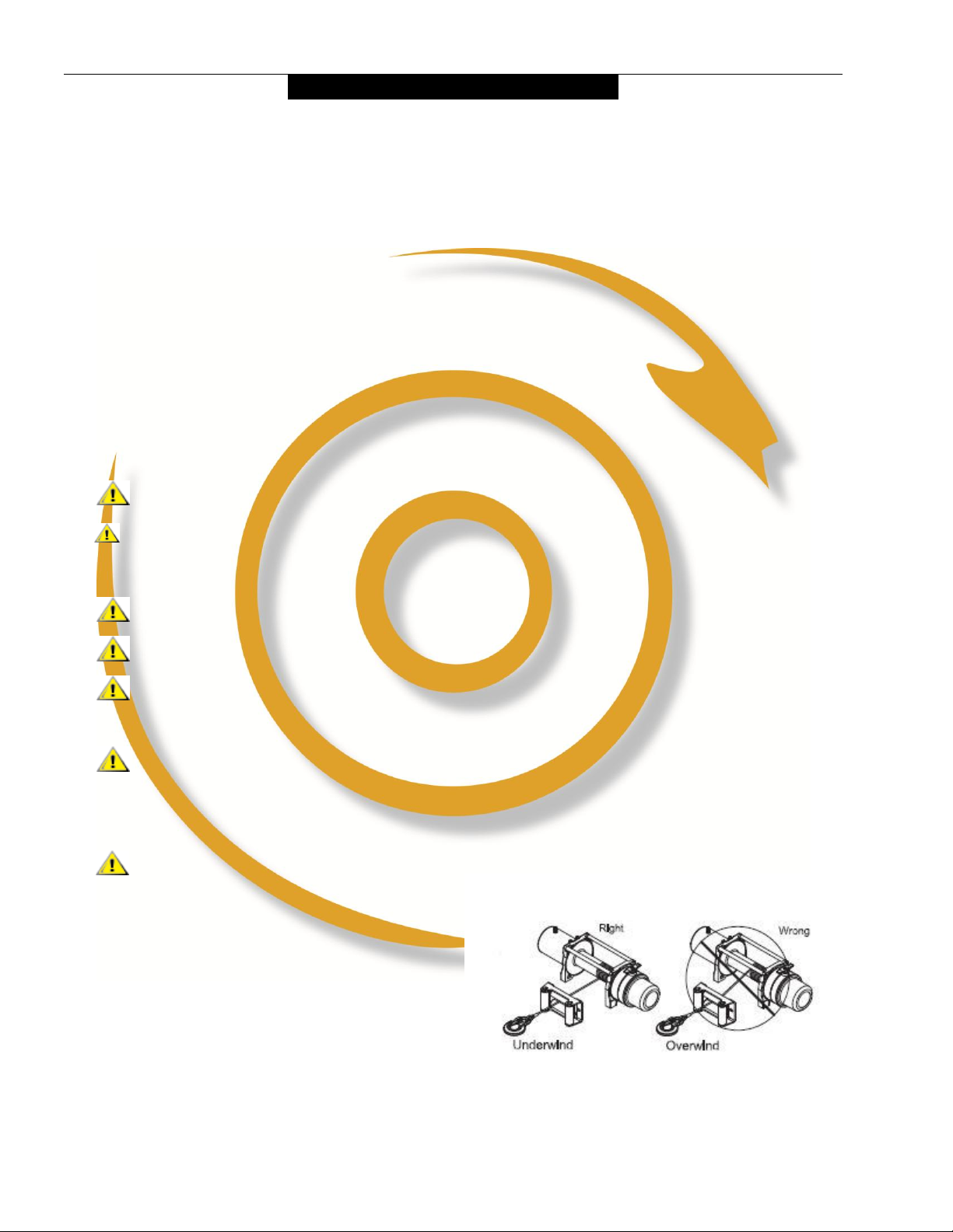
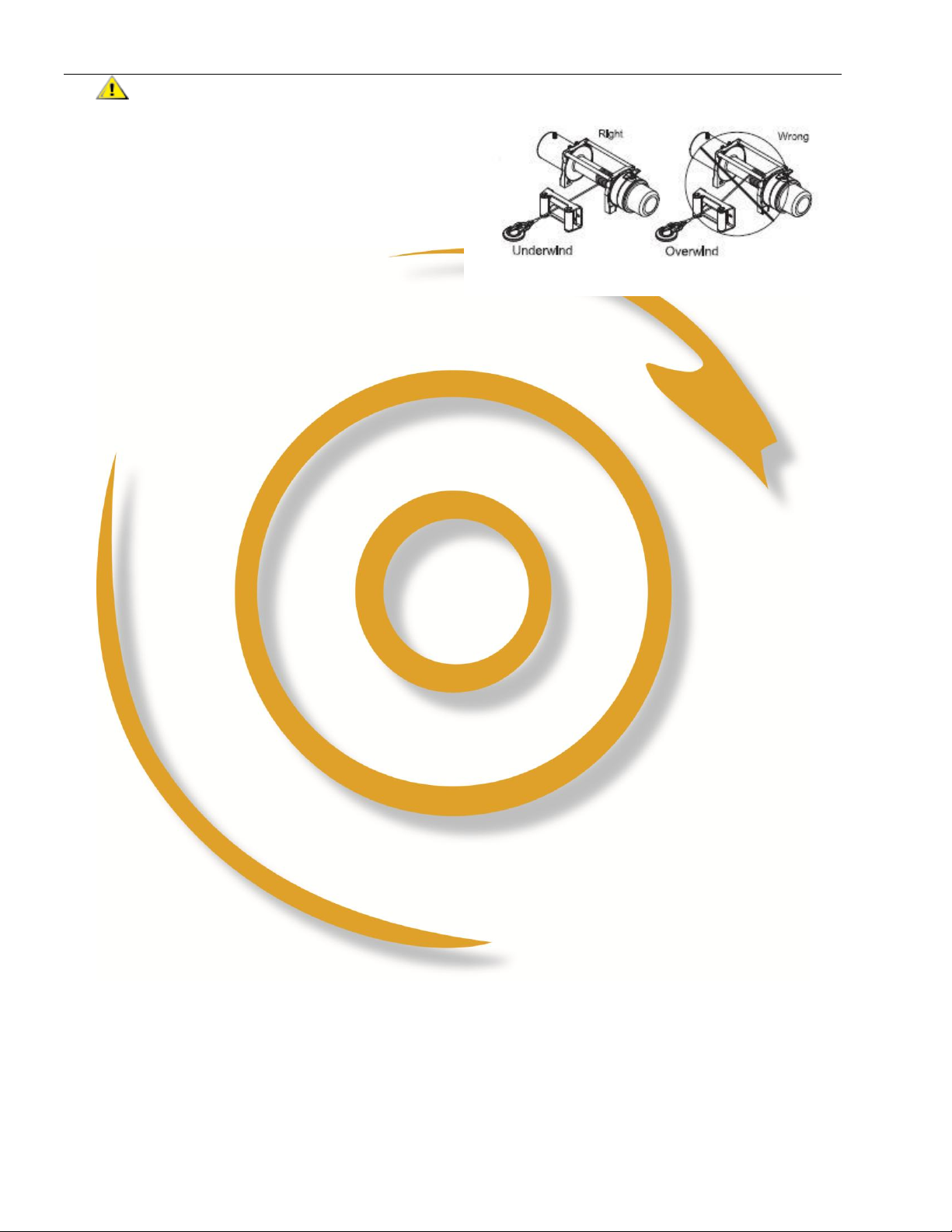
WARNUNG –Beim neu Aufwickeln
des Kabels sicherstellen das das Seil von
unten auf der Trommel gewickelt wird.
Ansonsten ist die Bremswirkung nicht
funktionell. Die Last wird runter schlüpfen
können.
Inspect the winch installation and bolts to ensure that all bolts are tight before each
operation. Use only the bolts which were delivered with the winch. Too long bolds will
damage the casted sides of the winch an may cause braking of the winch foots. Too
short bolds will not hold the load.
Inspektiere die Bolzen bevor Einsatz. Nehme nur die mitgelieferte Bolzen. Zu lange
Bolzen drücken innerhalb die Winde die Seiten der Drum völlich kaput. Dies leitet zur
abbruch der Winde von seiner Grundplatte. Zu kurze Bolzen halten nicht die Last.
Any winch that appears to be damaged in any way, is found to be worn, or operates
abnormally shall be removed from service.
Ein anscheinlich beschädigter Winde oder verschlissen sollte Mann direkt tauschen und
nicht gebrauchen.
The P winch should be fitted with a safety switch
Die P Winde sollte einen Abschalter des Haubtstroms haben entweder Manuel oder mit
ein Magnetschalter (Relais)
An (automatic ?) Amperage switch or fuse can be used to prevent overload of P winch. Use
a fuse of the max. indicated Amperage + 20 % (slow type ).
Ein (automatische) Ampere Sicherung vermeidet überlastung des Motors von P Winde.
Nehme dazu die Max Amperage + 20 % die angegeben wird für die Winde, nehme eine
‘langsahme’ Sicherung.

4
The winch must be properly mounted to a base which must be strong enough.
Die Winde muß Sachgemäß montiert warden auf genügend sterke Grundplatte oder boden.
Connect the battery and motor leads with thick enough electric wiring usable for given
Amperages for P Winch.
Nehme geiegneter Elektrikkabel für genügend Stromdurchlas für die auch auf der Ausenseite
der Verpackung angdeutete Amperes ( Strom ) für P Winde.
Take off the rope not needed of the drum. Too much rope must be removed.
Nie mehr Seil auf der Trommel lassen als nötig ist. Zuviel Seil also entfernen.
CAUTION: Always leave at least five turns of cable on the drum
VORSICHT: Immer aber 5 Wicklungen auf der Trommel lassen
Most winches don’t stop immediately for they have to drain some energy still, get used to
this phenomena.
Die meiste Winden stoppen nicht gleich, die Energie des Motors soll erst verschwinden,
gewönen Sie sich an dieses Phänomen.

5
MOUNTING DRAWING / MONTAGE ZEICHNUNG ELECTRIC P 2S

6
WARNING - Adjustment braking angle method: The
right adjustment between the two notches should be an
angle off 20°±5°. Check this, after some wear the angle
has to be adjusted.
WARNUNG - Nachstellung der Bremsbetätiger. Die
Haube mit Nocken nimmt in eine Drehrichtung die
Auflaufbremse mit. Um Verschleiß zu kompensieren muß
die Winkel adjustiert werden zwischen die Nocken aufs
Bild hierneben auf 20°±5°.
wn
bb

7
EXPLODED VIEW GW 4000 T 2S

8
PARTS LISTGW 4000 T 2S
No.
Part #
Qty
Description
Remark
1
P0800001
3
Terminal Protect
2
P0800100-U
1
Motor Assembly
Used in U and S type winch
P0800100-F
Used in F type winch
3
P0800002
6
Cap Screw M10 x 35
4
P0800003
6
Lock Washer Φ10
5
P0800004
6
Think Flat Washer Φ10
6
P0800005
4
Hex Nut M10
7
P0800200
1
Break / Shaft Assembly
8
P0800006
2
Bushing—Drum
9
P0800300
1
Gear Carrier Assembly (Input)
10
P0800007
1
Driving Sleeve
11
P0800008
2
Tie Bar
12
P0800009
2
Ring Seals
13
P0800400
1
Drum Assembly
14
P0800010
4
Locking Washer Φ8
15
P0800011
4
Cap Screw M8 x 30
16
P0800012
1
Cap Screw M8 x 10
17
P0800013
10
Screw M4 x 25
18
P0800014
10
Lock Washer Φ4
19
P0800015-U
1
End Bearing
Used in U and S type winch
P0800015-F
Used in F type winch
20
P0800016
1
Gasket
21
P0800500
1
Gear—Ring Assembly
22
P0800600
1
Gear Carrier Assembly (Output)
23
P0800700
1
Gear Carrier Assembly (Intermediate)
24
P0800017
1
Transmission Shaft
25
P0800018
1
Trust Washer
26
P0800800
1
Clutch Axes Assembly
27
P0800019
1
Slide Bushing
28
P0800020
1
Spring
29
P0800021
1
Clutch Housing
30
P0800022
1
Spring
31
P0800023
1
Cover-Gear Housing
32
P0800014
5
Lock Washer Φ4
33
P0800024
5
Screw M4 x 15
34
P0800900
1
Clutch Handle Assembly
35
P0800025
1
Screw M8 x 30
36
P0800026
2
Locknut M10
37
P0801000
1
Roller Fairlead
38
P0800027
1
Mounting Channel
By Choice
39
P0801100
1
Remote Control Switch(RC3)
40
P0801200
1
Cable Assembly
41
P0800028
1
Strap
42
P0801300
1
Control Section Of U Type Winch
By Choice
43
P0801400
1
Control Section Of SType Winch
By Choice
44
P0801500
1
Control Section Of F Type Winch
By Choice

9
DATA GW 4000 T 2S 230 V
Rated line pull
4082 kgf
Motor: series wound
230 V AC 2.2 kW
Gear reduction ratio
256:1(Low speed); 35:1(Fast speed)
Cable (Dia × L)
Ø8.3mm×29m
Drum size (Dia × L)
Ø63mm×223 mm
Mounting bolt pattern
254mm×114.3 mm 4 x M10
Item
Overall dimensions
(L×W×H)
594mm×192mm×283mm
Weight
kg
59.0
Low speed
Fast speed
Line Pull
Line Speed m/min
Line Pull
Line Speed m/min
kgf
230 V DC
kgf
230 V DC
0
5.3
0
42.1
1000
3.1
120
30.1
2000
2.6
210
23.2
3000
1.8
350
15.9
Layer
Rated line pull kgf
Total rope on drum m
1
3000
6.1
2
2500
13.5
3
2350
22.0
4
2000
29.0

10
WINCH g
DRAWING /
ZEICHNUNG GW 5500 P 2S

11
Table of contents
Popular Winch manuals by other brands

Ingersoll-Rand
Ingersoll-Rand Man Rider MR150K Series Product information

Wahlberg
Wahlberg 239.701 user manual

Kolpin Outdoors
Kolpin Outdoors KAWASAKI MULE PRO-FX Assembly & owners manual

Berger & Schroter
Berger & Schroter 31593 Instructions for use

goliath
goliath CS Series user manual

Antal
Antal XT40EH installation manual