golmar EL632/G+/48 User manual

WEB CLIENT
IP G+
EL632/G+/48
Web Client EL632/G+/48 REV0121 V04|ENGLISH
QUICK GUIDE

CATEGORY 1_HEADERCATEGORY 2_HEADER
2Footer Infos
INDEX
1. Before starting..................................................................................................................................................3
2. Access the web client........................................................................................................................................3
3. Web client.........................................................................................................................................................5
3.1. Settings.................................................................................................................................................................. 5
3.2 Push buttons.......................................................................................................................................................... 5
3.3. Calls via SIP protocol .......................................................................................................................................... 6
3.3.1. Add SIP device ............................................................................................................................................ 6
3.3.2. SIP servers.................................................................................................................................................... 8
3.4. Devices.................................................................................................................................................................. 9
3.5. Event log ............................................................................................................................................................... 12
3.6. About..................................................................................................................................................................... 12
www.golmar.es 2
IP G+ WEB CLIENT EL632/G+/48

3
CLIENTE WEB EL632/G+/48 IP G+
www.golmar.es
For the system conguration is not necessary any computer or soware, as the management panel assigns an IP address and registers
the monitors in the system. In case of advanced congurations, such as the SIP devices inclusion or additionals cameras, the use of the
web client will be necessary. In turn, as we will see in this guide, it also oers us other functions of interest, such as the export of system
conguration or the log events of the system.
To access the web client we will need to connect a computer to the installation.
For this, we will connect an ethernet wire from th IN of a D4L-G+/POE switch of our installation to the computer.
1. BEFORE STARTING
2. ACCESS THE WEB CLIENT
In installations where POE switches are used, for example to power CCTV cameras, it will be possible make use of an UP-LINK port
of this one to connect the laptop.
2
2
2
PRI 230V50/60HZ
SEC: 12V6VA
12V
230V
TF-104
TF-104
D1 D2
IN OUT
D3 D4
D4L-G+/PoE
+-
18Vdc
Power
Columna
Riser
Local
D4L-G+/PoE
11:40
AM
20-02-2019 Wed
Doorpa nel Intercom Recordings Settings
FA-G+
UTP UTP
UTP
12340100 FA-G+
Local
Local Power
2
2
2
PRI 230V50/60HZ
SEC: 12V6VA
12V
230V
TF-104
TF-104
D4L-G+/PoE
11:40
AM
20-02-2019 Wed
Doorpa nel Intercom Recordings Settings
FA-G+
UTP UTP
UTP
12340100 FA-G+
UTP
SW-104
POE UP-LINK
1 2 3 4 5-UP 6-UP
S
V
P
V
N S
UP-LINK
PORTS
POE
PORTS
SW-104
D1 D2
IN OUT
D3 D4
D4L-G+/PoE
+-
18Vdc
Power
Columna
Riser
Local
UTP
Once the laptop is connected, we must connect to the IP address of the management panel through a web browser (Chrome,
Explorer…).
In case that we are connecting to the management panel and we have selected the automatic IP address, the assigned IP address
will be 10.0.14.9. If the panel has not been previously congured, its factory IP address will be 10.0.0.254. In case of not knowing
the management panel IP address having assigned it manually, you can see it accessing to the “About” section of any monitor of the
installation. Other option is to search all the IP addresses in the system through the “Device Manager” soware.
Nexa panel with
EL632/G+ module
Nexa panel with
EL632/G+ module
NOTE. To know how access to the “About” section of a monitor, see the ART 7/G+ user manual that you will nd in the downloads
section of the product’s website.

4
WEB CLIENT EL632/G+/48IP G+
www.golmar.es
Type the IP address in the web browser:
GO
10.0.14.9
Search
GO
10.0.14.9
Search
e password to access is 888999.
Before typing the management panel IP address in the web browser, we must make sure that the network connection of the computer is
on the same IP range. For this we will follow the next steps:
In this moment the computer is congurated to work in the same IP range as the management panel.
Only will le:
Access the Web Client:
Go to network settings in control panel. Change the active Ethernet network.
Enter into “properties”. 4Select Internet
protocol IPv4.
5Set the IP range.
IP address should start by 10.
Next three numbers should
have a value lower than 255.
Assign 10.0.0.1 as Gateway.
Do not assign DNS
(blank elds). Conrm settings.
1 2
3

5
IP G+
www.golmar.es
Below, the dierent sections of the web client are described:
3. CLIENTE WEB
In the push buttons section we will be able to set the address to which we will call when we press one push buton or other. We will also be able
to select if it is a single push button module panel or double push button module panel.
3.2. Push buons
From the rst settings screen we can modify the entry panel conguration. It also allows to change the panel IP address and set a
dierent one that the system automatically assigns.
3.1. Sengs
Date and time setting
Allow/Not allow changes in the device
conguration.
Floor number where the device
is(1-96).
(Necessary if the LCU-16/G+ li controller unit
is available).
Openning button operataion mode.
0 = Normally open / 1 = Normally closed
Openning time delay time.
Door openning time (1-15s).
DOOR PANEL
Apply
Settings
Push buttons
Event log
About
SIP servers
Devices
Next
Network
Automatic settings
Local IP
Gateway
Server IP
Subnet Mask
10.0.14.9
IP Address 10.0.14.40
10.0.0.1
255.0.0.0
255.0.0.0
Set as main
Associate camera
Floor number
Door panel number
Block number
Dialing code length
1
1
1
5
Devices edition allowed
DNS 8.8.8.8
Time
Date
16:59
23/ 11 / 20
Manual IP address entering.
Remember that the Server IP address
is the management panel IP address.
Apply
Settings
Push buttons
Event log
About
Devices
Illumination leds *
Prompt messages **
2
0
* Illumination modes
** Prompt modes
0 OFF - 1 ON - 2 Auto
0 OFF 3 Dutch
1 Spanish 4 English
2 Danish 5 French
6 Greek
7 Portuguese
DOOR PANEL
Previous
SIP servers
Lock 1
Unlock time
Exit button delay time
3
0
0
Exit button unlock mode *
Lock 2
Unlock time
* Unlock modes
0 Normally Open - 1 Normally Closed
3
8 Ring tones
Exit button delay time
0
0
Exit button unlock mode *
Camera disabled
Illumination leds mode.
0 = OFF / 1 = ON / 2 = Automatics
Enable/Disable the camera.
Prompt messages modes.
0 = OFF / 1-8 = Dierentes languages
Save changes set.
Go to the previous screen.
Go to the next screen.
Log out from the web client.
CLIENTE WEB EL632/G+/48
Dialing code length.
Block number.
Panel number.
(*) When you do a preview of the entry panel, the diplayed image will be from the assciated camera.
Associate an IP camera.
Camera IP address.
(*)Set as main camera.
Settings
Push buttons
Event log
About
10 20 30
9 19 29
66 8 18 28
7 17 27
6 16 26
5 15 25
4 14 24
3 13 23
2 12 22
1 11 21
Devices
Apply
010 020 030
009 019 029
66 008 018 028
007 017 027
006 016 026
005 015 025
004 014 024
003 013 023
002 012 022
001 011 021
PUSH BUTTONS
Next
Right
Built-in push buttons
Reset
SIP servers
Single push button type
Settings
Push buttons
Event log
About
Devices
Apply
PUSH BUTTONS
40 50 60
39 49 59
38 48 58
37 47 57
36 46 56
6535 45 55
6434 44 54
6333 43 53
6232 42 52
6131 41 51
040 050 060
039 049 059
038 048 058
037 047 057
036 046 056
065035 045 055
064034 044 054
063033 043 053
062032 042 052
061031 041 051
Previous
SIP servers
- Single push buttons module panel:
Go to the next screen.
Go to the previous screen.
Save changes set.
Reset default settings.
To modify the call addresses of every push button, we must press on the push button number and set de desired call address.

6
IP G+
www.golmar.es
WEB CLIENT EL632/G+/48
- Double push buttons module panel:
Settings
Push buttons
Event log
About
10 20 30
9 19 29
132
131
8 18 28
7 17 27
6 16 26
5 15 25
4 14 24
3 13 23
2 12 22
1 11 21
Devices
Apply
010 020 030
009 019 029
132
131
008 018 028
007 017 027
006 016 026
005 015 025
004 014 024
003 013 023
002 012 022
001 011 021
PUSH BUTTONS
Next
Left
Right
Built-in push buttons
Reset
SIP servers
Single push button type Settings
Push buttons
Event log
About
Devices
Apply
PUSH BUTTONS
Next
7040 8050 9060
6939 7949 8959
6838 7848 8858
6737 7747 8757
6636 7646 8656
6535 7545 8555
6434 7444 8454
6333 7343 8353
6232 7242 8252
6131 7141 8151
070040 080050 090060
069039 079049 089059
068038 078048 088058
067037 077047 087057
066036 076046 086056
065035 075045 085055
064034 074044 084054
063033 073043 083053
062032 072042 082052
061031 071041 081051
Previous
SIP servers
Settings
Push buttons
Event log
About
Devices
Apply
PUSH BUTTONS
130100 110 120
12999 109 119
12898 108 118
12797 107 117
12696 106 116
12595 105 115
12494 104 114
12393 103 113
122
92 102 112
12191 101 111
130100 110 120
129099 109 119
128098 108 118
127097 107 117
126096 106 116
125095 105 115
124094 104 114
123093 103 113
122092 102 112
121091 101 111
Previous
SIP servers
Go to the next screen.
Reset default settings. Go to the previous screen.
Save changes set.
To modify the call addresses, we will assign the desired call address to every push button number in the same way as single push buttons
module panel.
3.3. Calls via SIP protocol
e system allows calls using VoIP telephones via the SIP protocol. ere are two dierent ways to do it, adding the VoIP telephone
directly to the system or using a PABX telephone switchboard to act as a liaison between telephones and the system through extensions
that we will assign to the dierent devices of the system.
e following describes the two ways to make calls using the SIP protocol:
3.3.1. Add SIP device
In this section will show how to include a VoIP telephone with SIP protocol. In this case the call process is done directly. at is to say, the
system knows the VoIP telephone IP address and not an extension that it must ask to the switchboard.
Steps to follow:
1 - Connect the device to the system:
2
2
2
PRI 230V50/60HZ
SEC: 12V6VA
12V
230V
TF-104
TF-104
D1 D2
IN OUT
D3 D4
D4L-G+/PoE
+-
18Vdc
Power
Columna
Riser
Local
D4L-G+/PoE
11:40
AM
20-02-2019 Wed
Doorpanel Interc om Recordings Settings
FA-G+
UTP UTP
UTP
12340100 FA-G+
UTP
SW-104
POE UP-LINK
1 2 3 4 5-UP 6-UP
S
V
P
V
N S
UP-LINK
PORTS
PORTS
SW-104
UTP
230V
POE
The used VoIP telephone is powered by 5Vdc.
Therefore, an Up-Link port has been used to receive only data
and to feed it locally with its power supply.
2 - SIP device IP address:
It will be necessary to know the device IP addres. Generally, VoIP telephones allow to show it on the telephone’s own display. If not, it is
possible to use programmes such as the one mentioned above “IP search Tool”.
If the device IP address is not in the same range as the system, it will be necessary to change it for one that is 10.XX.XX.XX. (remember
that the PC must be in the same range). See the process of modifying the phone manufacturer’s IP address.
Nexa panel with
EL632/G+ module.

7
IP G+
www.golmar.es
CLIENTE WEB EL632/G+/48
3.3.2. SIP servers
In the SIP servers section we will be able to add the device in a PABX telephone switchboard in order to receive calls using an extension
through the switchboard. e steps to follow to add the device in a switchboard are shown below:
We will connect the PABX telephone switchboard
to our network through the LAN output of the
switchboard. In this way, we will be able to access its
web client and set an IP range of the WAN output of the
switchboard. which is where we will connect it to our
system for its operation.
In our web browser we will type the IP address of the
LAN network of the switchboard.
1
Will ask us for our credentials in order to access. In the back of the PABX
appears the user, that usually is “admin” and the password.
In this example we will use the UCM6202 PABX. Other switchboards can dier in terms of its programming. See the manual of your
switchboard.
IP POR DEFECTO DEL TELÉFONO
Type the current IP address of the telephone in the web browser:
Save the changes and reboot the telephone.
Access to the network section and modify the IP and the Gateway.
IP POR DEFECTO DEL TELÉFONO
Access with the manufacturer credentials.
3 - Modify the IP address:
IP range 10.XX.XX.XX
Gateway 10.0.0.1
4 - Add the telephone to the system:
Access to “devices” section of the management panel (described above in this guide):
Push buttons
SIP servers
GMS
Press on
“add SIP device”.
Telefono voIP
IP address 10.128.1.150
0
0 IP - 1 to 30 SIP server
Name to identify the device.
Block associated with the device.
Address call assigned to the device.
Conection “0” by IP address.
Add.
Device IP address.
In this moment the telephone is added and it appears in the devices list, in this example belongs to the block 1.
In case of a call to the address 10 we would establish communication. We will be able to open the relays 1 and 2 through #1 and #2
respectively during communication.
In this guide has been used the Grandstream GXP1610 model. e following describes how to modify its IP address:

IP G+ WEB CLIENT EL632/G+/48
Having already congured the WAN network to work
in the same IP range as our system, the next step will be
to create an extension in the switchboard for our device.
For this, we deply the “Extension/Trunk” section and we
access the “Extensions” section.
In this screen will appear all the created extensions in
the switchboard.
e “+Add” option will allow us to create a new
extension for our device.
We will add the desired extension and a password.
To conrm the new extension created, we will press on “Save”.
NOTE: Remember the password, you will need it later.
3
When we have added the extension, it will be necessary to save the applied changes. On the top of the screen will appear
the icon . We will press on it and the new extension will have been saved.
Having saved the changes made, the screen will
show us that exists a created extension in the
switchboard, which we will use for our device,
but this one has not yet been registered.
8www.golmar.es
Once we have accessed the switchboard web server, we
deploy the system settings pressing on “System Settings”
and we will access to the “Network Settings”.
In the WAN section, we will set an IP address which is
in the IP range of our system. We will also have to set the
subnet mask and the corresponding Gateway address.
2
IMPORTANT: Connect the PABX to our network through the WAN output of this one.

9
IP G+
www.golmar.es
CLIENTE WEB EL632/G+/48
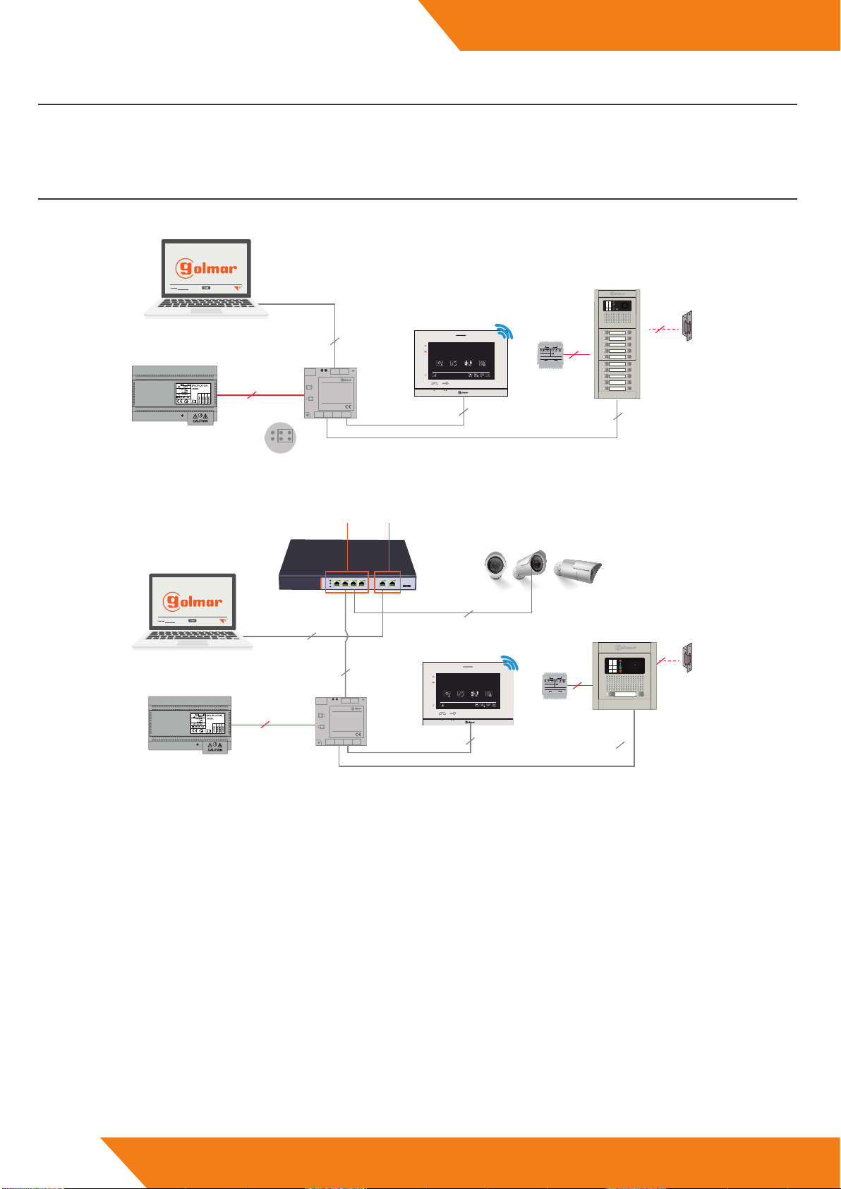
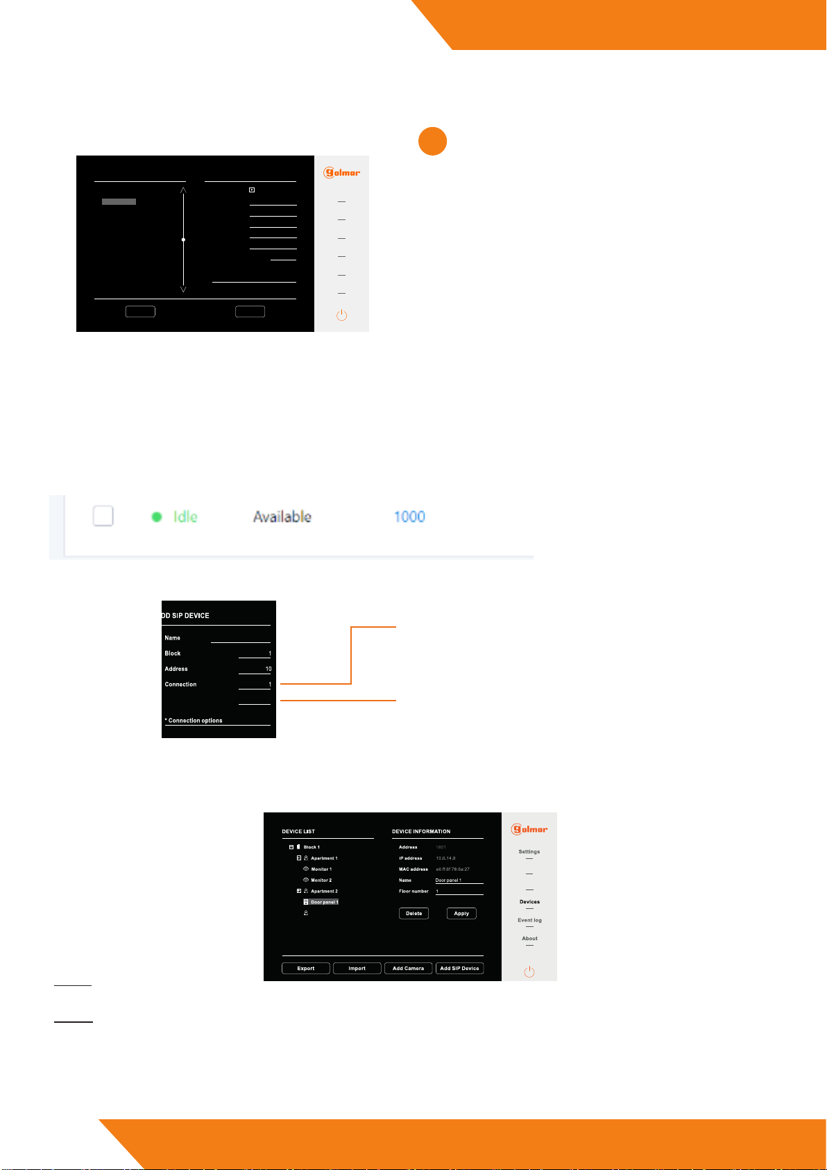
In devices we nd a list of the existing devices in the installation. We can consult its conguration and edit certain aspects of this:
3.4. Devices
Push buttons
SIP servers
GMS
We can export the conguration to do backup copies.
From devices we also have the possibility to add ONVIF cameras and SIP devices to the installation. ese are discussed in detail below.
Export
Import
In case in the future the backup copy has to be retrieved, this could be dumped via the import option, loading the .db le that was generated
in the export.
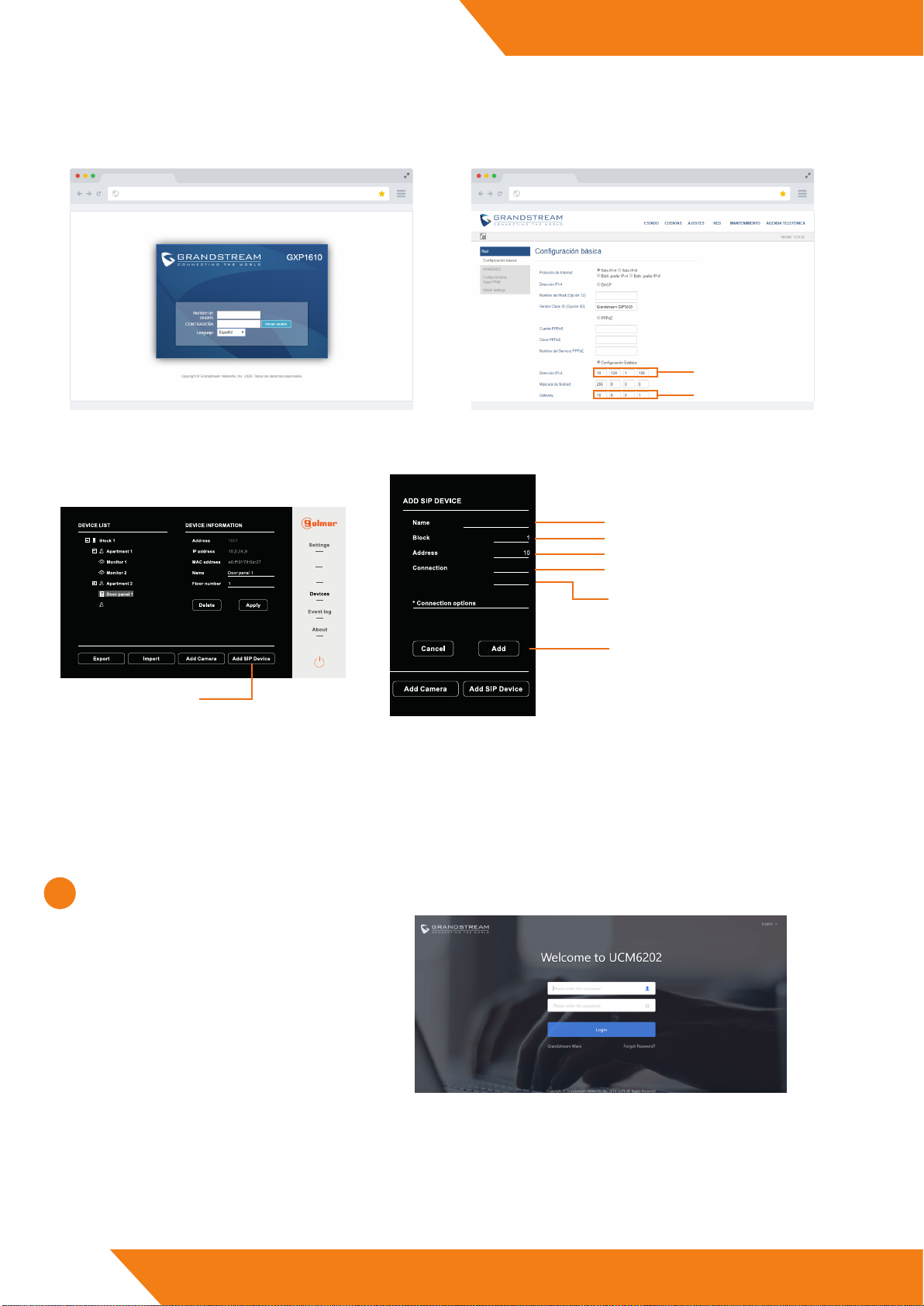
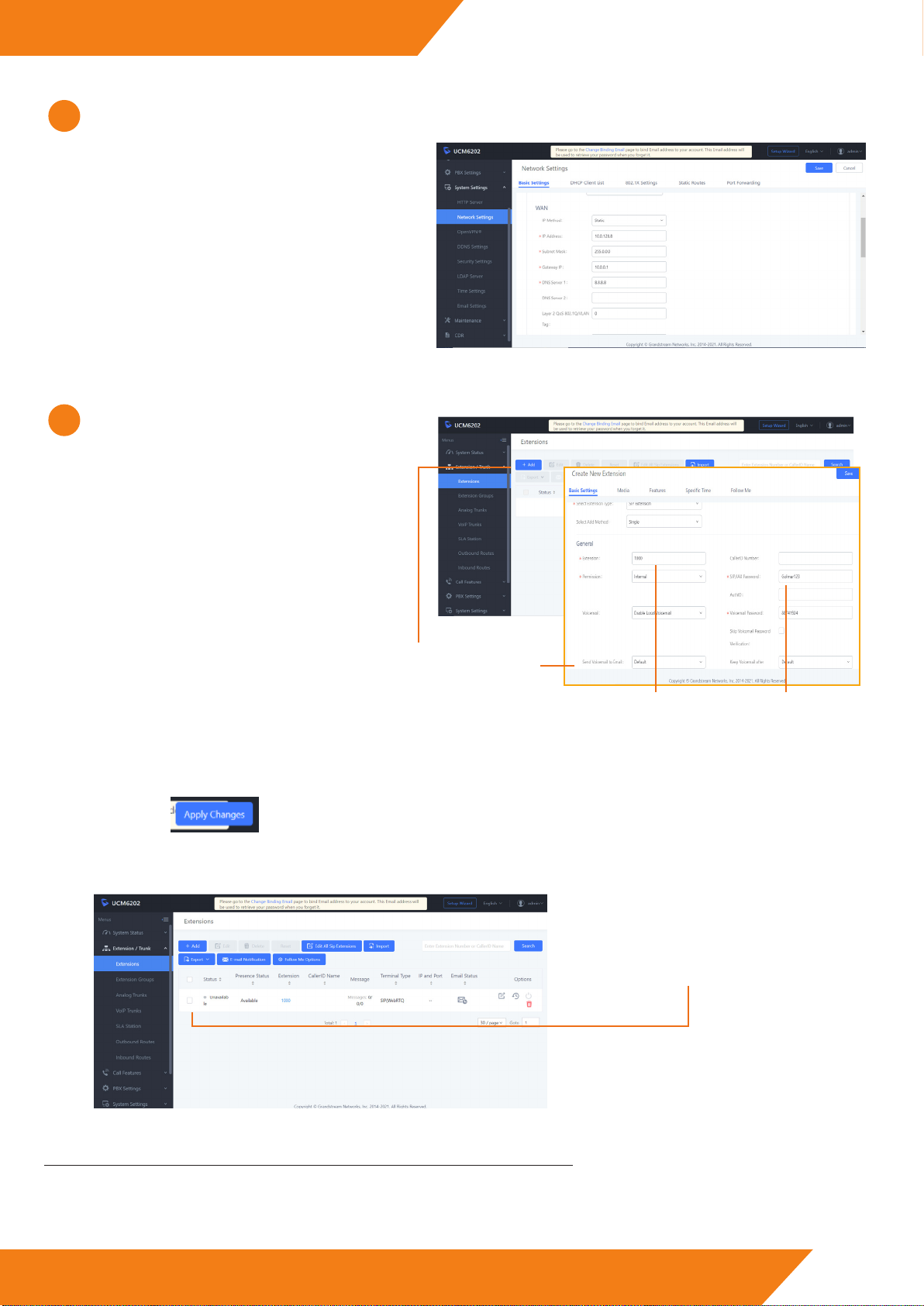
To check that we have done correctly all the steps, we access to the PABX web server and we see the state of the extension that we had
previously created.
We note that the state of the extension has
change from “Unavailable” to “Available”
and it has turned green.
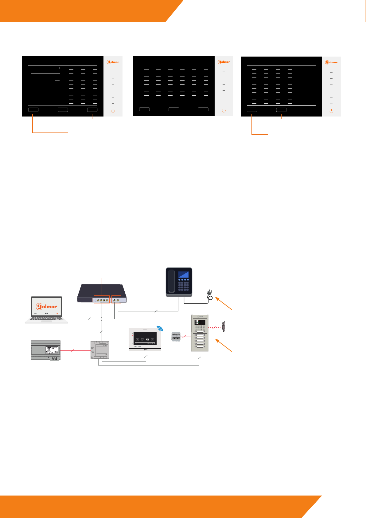
To assign the previously created extension to our device, in this case an entry panel, we will access the client web and we will go to the
“SIP servers” section. e next screen will appear:
SERVER INFORMATION
Enabled
IP address
Name
Port
User
Password
SERVER LIST
1
2
3
4
5
6
7
8
9
10
Golmar
Settings
Push buttons
Event log
About
Devices
Office 1
0
Transmission mode *
* Transmission modes
0 UDP - 1 TCP
Delete Apply
5060
SIP servers
Grandstream Grandstream
10.0.128.8
1000
********
4
We note, on the le part of the screen, a list of up to 30 SIP
servers that should be empty, as we have not yet added the
panel to any telephone switchboard.
When select one of the numbers of the list, elds appear
which must be lled in and the enable disable the SIP
server option.
• Name: Name to assign to the SIP server.
• IP Address: PABX IP address that we have
congurated (WAN).
• Port: 5060. is port is usually the default port on
most switchboards.
• User: Extension number created.
• Password: e set password on the PABX web server.
• Transmisssion mode: 0 UDP. TCP mode is not
implemented in this version
Once we have lled in all the elds, we click on “Apply” to
save the created server. If it is correct, the “Settings applied”
message will appear. If some of the parameters was incorrect either
no connection can be established with the switchboard, an error
message will appear “Login fail”.
1000
Only will le to add the VoIP telephone to the system having previously created an extension in the switchboard. For this we will follow
the same steps described above, but when we access to the “Add SIP device” section we will ll in the elds as follows:
Telefono voIP
Telephone extension
302
0 IP - 1 to 30 SIP server
Number of appearance in the list of SIP servers
of the system of the SIP server created in the
PABX.
Extension created in the switchboard for the
VoIP telephone.

10
IP G+
www.golmar.es
WEB CLIENT EL632/G+/48
Add Camera
e system allows to add Golmar cameras with the following specications:
• ONVIF interface protocol.
• H.264 video codec standard, “baseline” mode support.
(*) Golmar does not guarantee the compatibility of cameras from other manufacturers.
Steps to follow:
1 - Connect the camera to the system:
In this scheme the camera receives data and power
from the 48Vdc switch.
It is possible to send data from a switch and power the
camera locally with its power supply.
2
2
2
PRI 230V50/60HZ
SEC: 12V6VA
12V
230V
TF-104
TF-104
D4L-G+/PoE
11:40
AM
20-02-2019 Wed
Doorpanel Intercom R ecordings Settings
FA-G+
UTP UTP
UTP
12340100 FA-G+
UTP
SW-104
POE UP-LINK
1 2 3 4 5-UP 6-UP
S
V
P
V
N S
UP-LINK
PORTS
POE
PORTS
SW-104
D1 D2
IN OUT
D3 D4
D4L-G+/PoE
+-
18Vdc
Power
Columna
Riser
Local
UTP
Nexa panel with
EL632/G+ module.
2 - Know the camera IP address:
Discover the IP address assigned to the camera. If the default IP address of the camera is not reected, we can nd out the IP address
by using programs such as “IP search Tool”:
3 - Access the camera conguration environment:
Once we know the camera IP address and our computer is in the same range, we type the IP address in the web browser and we access the
camera settings (similar process to the one described at the beginning of the guide but in this case with the camera).
GO
10.0.99.99
Search
Type the IP camera in the web browser:
e Golmar camera credentials used in this guide are the following::
User: admin, Password: admin
(*) Check which are the access credentials of your camera.
Access the web client of the camera:
10.0.99.99
(*) If the camera is Golmar, use the Internet Explorer browser.

11
IP G+
www.golmar.es
CLIENTE WEB EL632/G+/48
Conguration Selection to mark
Resolution 640 x 480 (máx)
FPS 25
Compression H.264
Codication type Baseline
Bit Rate type CBR
Bit Rate 512
I frame interval 20ms
5 - Set the following substream conguration:
NOTE: It is possible that in some moment the web browser indicates that is required to install “plugins”, if it is the case you must install
them and reboot the web browser. If you change the access credentials, keep them in mind, as they are necessary to register the camera in
the system.
6 - Register the congurated camera in the system:
Access the “devices” section of the management panel (described above in this guide):
Push buttons
SIP servers
GMS
Click on
“add Camera”
admin
admin
10.128.0.125
Cámara 1
Name to identify the camera
Camera IP address
Camera credentials
4 - Modify the IP address.
e Gateway IP address should become
10.128.0.1
e camera IP address will have
to be changed to a value between
10.128.XX.XX and 10.254.XX.XX.
If the conguration of the IP addresses of the system
is automatic, use this recommenden parameters. If the
cameras IP addresses are given in other range, you can
congure the system IP addresses in manual mode.

12
IP G+
www.golmar.es
WEB CLIENT EL632/G+/48
In this moment the camera is added and appears in the devices list:
It is possible to select which devices have
access to the camera images.
For this, click on the “visibility” option and
select the devices of the deployable to which
you wish to give authorisation.
It is possible to check the dierent actions performed by the system from this screen as well as export these logs in .CSV le through
the “Export” option.
In “about” we will be able to see the panel information, update its rmware or modify the password to access the web client:
3.5. Event log
3.6. About
Push buttons
SIP servers
Push buttons
SIP servers
Door panel number
Server IP 10.0.14.9 Password to acces the web client.
(Keep in mind the new password in case of modication)
Firmware version.
Hardware version.
Panel information.
Update the panel
rmware.
Reboot the panel.
Push buttons
SIP servers
Cámara 1
10.128.0.125
Cámara 1

Sist
emas de comunicación S.A.
C/ Silici 13. Poligon Industrial Famadas
08940 – Cornellà del llobregat – Spain
golmar@golmar.es
Telf: +34 934 800 696
www.golmar.es
Golmar reserves the right to make any changes without prior notice.
Other manuals for EL632/G+/48
1
This manual suits for next models
1
Table of contents
Other golmar Recording Equipment manuals