Goodman HKS User manual

A
TTENTION
I
NSTALLING
P
ERSONNEL
As a professional installer, you have an obligation to know
the product better than the customer. This includes all safety
precautions and related items.
Prior to actual installation, thoroughly familiarize yourself
with this Instruction Manual. Pay special attention to all
safety warnings. Often during installation or repair, it is
possible to place yourself in a position which is more haz-
ardous than when the unit is in operation.
Remember, it is your responsibility to install the product
safely and to know it well enough to be able to instruct a
customer in its safe use.
Safety is a matter of common sense...a matter of thinking
before acting. Most dealers have a list of specific good safety
practices...follow them.
TheprecautionslistedinthisInstallationManualareintended
as supplemental to existing practices. However, if there is
a direct conflict between existing practices and the con-
tent of this manual, the precautions listed here take prece-
dence.
S
AFETY
P
RECAUTIONS
The following symbols and labels are used throughout this
manual to indicate immediate or potential safety hazards.
It is the owner’s and installer’s responsibility to read and
comply with all safety information and instructions accom-
panying these symbols. Failure to heed safety information
increases the risk of personal injury, property damage, and/
or product damage.
HIGH VOLTAGE !
D
ISCONNECT
ALL
POWER
BEFORE
SERVICING
.
M
ULTIPLE
POWER
SOURCES
MAY
BE
PRESENT
. F
AILURE
TO
DO
SO
MAY
CAUSE
PROPERTY
DAMAGE
,
PERSONAL
INJURY
OR
DEATH
.
WARNING
ONLY
INDIVIDUALS
MEETING
THE
REQUIREMENTS
OF
AN
“E
NTRY
L
EVEL
T
ECHNICIAN
”,
AT
A
MINIMUM
,
AS
SPECIFIED
BY
THE
A
IR
-
C
ONDITIONING
, H
EATING
,
AND
R
EFRIGERATION
I
NSTITUTE
(AHRI)
MAY
USE
THIS
INFORMATION
. A
TTEMPTING
TO
INSTALL
OR
REPAIR
THIS
UNIT
WITHOUT
SUCH
BACKGROUND
MAY
RESULT
IN
PRODUCT
DAMAGE
,
PERSONAL
INJURY
,
OR
DEATH
.
WARNING
HKS
ELECTRIC HEAT KIT
INSTALLATION INSTRUCTIONS
T
HIS
APPLIANCE
MUST
BE
INSTALLED
FOLLOWING
THE
ANSI/NFPA
70 (N
ATIONAL
E
LECTRIC
C
ODE
)
AND
OTHER
APPLICABLE
CODES
.
WARNING
F
AILURE
TO
FOLLOW
THESE
INSTRUCTIONS
CAN
CAUSE
FIRE
,
EXPLOSION
,
ELECTRICAL
SHOCK
,
PROPERTY
DAMAGE
,
PERSONAL
INJURY
OR
DEATH
.
WARNING
T
O
AVOID
POSSIBLE
PERSONAL
INJURY
,
USE
EXTREME
CAUTION
IS
USING
POWER
TOOLS
TO
REMOVE
THE
SMALL
BREAKER
MOUNTING
BRACKETS
.
T
HE
BRACKETS
MAY
QUICKLY
ROTATE
AND
CAUSE
INJURY
.
OR
DEATH
.
CAUTION
CARBON MONOXIDE POISONING HAZARD
Special Warning for Installation of Furnace or Air Handling Units in
Enclosed Areas such as Garages, Utility Rooms or Parking Areas
Carbon monoxide producing devices (such as an automobile, space
heater, gas water heater, etc.) should not be operated in enclosed areas
such as unventilated garages, utility rooms or parking areas because of
the danger of carbon monoxide (CO) poisoning resulting from the exhaust
emissions. If a furnace or air handler is installed in an enclosed area such
as a garage, utility room or parking area and a carbon monoxide producing
device is operated therein, there must be adequate, direct outside
ventilation.
This ventilation is necessary to avoid the danger of CO poisoning which
can occur if a carbon monoxide producing device continues to operate in
the enclosed area. Carbon monoxide emissions can be (re)circulated
throughout the structure if the furnace or air handler is operating in any
mode.
CO can cause serious illness including permanent brain damage or death.
B10259-216
IO-776E
06/2018

2
S
HIPPING
I
NSPECTION
All units are securely packed in shipping containers tested
according to ISTAspecifications. The carton must be checked
upon arrival for external damage. If damage is found, a
request for inspection by carrier’s agent must be made in
writing immediately.
Inspect the kit carefully on arrival for damage and screws
or wires which may have come loose in transit. In the event
of damage the consignee should:
1. Make a notation on delivery receipt of any visible
damage to shipment or container.
2. Notify carrier promptly and request an inspection.
3. With concealed damage, carrier must be notified as soon
as possible - preferably within five days.
4. File the claim with the following support documents
within a nine month statute of limitations.
• Original or certified copy of the Bill of Lading, or
indemnity bond.
• Original paid freight bill or indemnity in lieu thereof.
• Original or certified copy of the invoice, showing
trade and other discounts or reductions.
• Copy of the inspection report issued by carrier’s
representative at the time damage is reported to
carrier.
The carrier is responsible for making prompt inspection of
damage and for a thorough investigation of each claim. The
distributor or manufacturer will not accept claims from
dealers for transportation damage.
S
TANDARD
A
IR
HANDLER
I
NSTALLATION
HKS
ELECTRIC
HEATER
KITS
MAY
ONLY
BE
INSTALLED
IN
ARUFXX14YY,
ARPTXX14YY, ASUFXX14YY, ASPTXX14YY, AVPTXX14YY,
DVXXPTC14YY
MODELS
(
WHERE
XX
IS
THE
TWO
-
DIGIT
SIZE
AND
YY
ARE
REVISION
LETTERS
).
WARNING
ONLY
INSTALL
HEATER
KITS
INTO
AN
AIR
HANDLER
THAT
ARE
LISTED
AS
APPROVED
ON
THE
RATING
PLATE
OF
THE
AIR
HANDLER
.
WARNING
T
O
PREVENT
PERSONAL
INJURY
OR
DEATH
WHEN
INSTALLING
IN
A
GARAGE
,
THE
ELEMENT
MUST
BE
AT
LEAST
18”
ABOVE
THE
FLOOR
.
WARNING
T
O
AVOID
PROPERTY
DAMAGE
OR
PERSONAL
INJURY
DUE
TO
FIRE
,
USE
ONLY
COPPER
CONDUCTORS
.
CAUTION
1. Remove the upper access panel from the air handler.
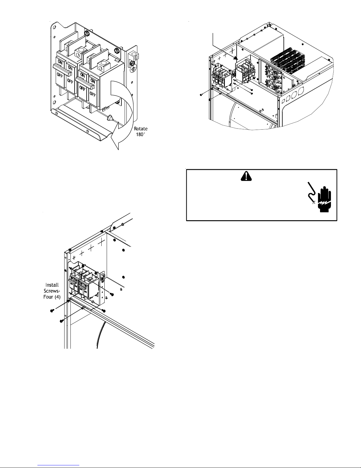
2. Remove and retain the four (4) screws securing the cover
plate. Remove and discard the cover plate.
3. For electric heat kits with circuit breakers, remove the
two screws securing the circuit breaker mounting plate
to the electric heat face plate.
NOTE: The circuit breakers for the 25kW are placed
separately in the carton and are not attached to the
heater plate.
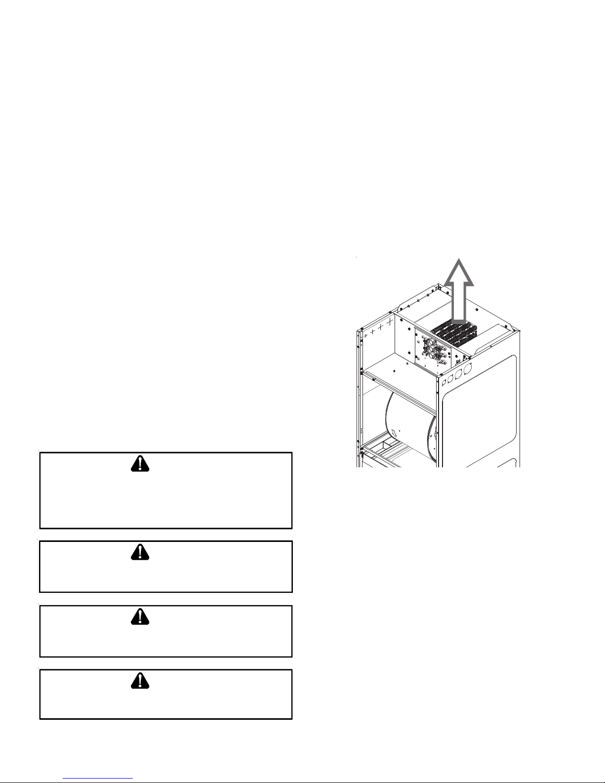
4. Slide the electric heat kit into the opening in the air
handler, making sure the direction of airflow decal
attached to the electric heat face plate is pointing in
the correct direction, and secure the electric heat face
plate using the screws removed in Step 2. Use caution
to not bend or damage the electric heating elements,
the limit switches or fuses during this process. See Figure
1.
Airflow
Direction
Figure 1
5. For downflow applications with electric heat kits that
have circuit breakers, the circuit breakers must be
rotated 180 degrees (such that the ON position will
be with the circuit breaker handles up). To do so,
remove and retain the 2 screws securing the circuit
breaker clamps, rotate the circuit breakers and
clamps 180 degrees, then use the same 2 screws to
re-secure the circuit breakers. See Figure 2.

3
Figure 2
6. For all electric heat kits with circuit breakers, mount
the circuit breaker mounting bracket as shown in Figure
3, using the supplied screws. Insert the four (4) screws
as shown in Figure 3 (two through the control panel
flange and two into the cabinet corner post).
For 25kW applications, see Figure 4 for installation.
Figure 3
Install
Screws -
Six (6)
25kW
Figure 4
E
LECTRICAL
C
ONNECTIONS
HIGH VOLTAGE !
D
ISCONNECT
ALL
POWER
BEFORE
SERVICING
.
M
ULTIPLE
POWER
SOURCES
MAY
BE
PRESENT
. F
AILURE
TO
DO
SO
MAY
CAUSE
PROPERTY
DAMAGE
,
PERSONAL
INJURY
OR
DEATH
.
WARNING
1. All electric heat kits have lugs for connection of high
voltage power supply. Insert the power leads into the
lugs (either on the terminal block or circuit breaker)
and tighten. The power must be routed through a strain
relief as they enter the cabinet. For two power supply
electric heat kits (all circuit breaker connections), be
sure to connect the correct power supply to the correct
circuit breaker – check the air handler rating plate for
Minimum Circuit Ampacity and Maximum Overcurrent
Protection electrical ratings of each circuit.
2. Connect the ground wire from the power supply to the
ground lug provided in the air handler. For two power
supply electric heat kits, one ground lug is provided
withtheairhandlerandthesecondgroundlugissupplied
with the electric heat kit (on the circuit breaker
mounting plate). Use proper torque to secure the ground
wire to the ground lug.
3. For low voltage connections, remove the female multi-
pin connector with the jumper wire provided with the
air handler from the male multi-pin connecter provided
with the air handler. Insert the female multi-pin
connector provided with the electric heat kit into the
male multi-pin connector provided with the air handler.
Note: it can be inserted in one position only.
4. FORALL THREE PHASEAPPLICATIONS: Wire the terminal
block leads to the transformer as per the wiring diagram
on the heat kit. Insert single and three phase power
leads into the lugs provided on the terminal block and
the circuit breaker respectively, and tighten.

4
5. FOR 25kW AND THREE PHASE HEAT KIT APPLICATIONS:
Install the wiring diagram provided with the heat kit in
a prominently visible location on the exterior of the
unit.
6. FOR ALL HEAT KITS: Mark an “X” on the wiring diagram
according to the number of heater element rows
installed.
S
TART
-U
P
1. Double check all electrical connections and screws to
ensure proper installation.
2. Replace the upper access panel on the air handler.
3. Make sure all circuit breakers and electrical power
supply are on.
4. Install an ammeter on the power supply(s) to the air
handler.
5. Turn the room thermostat setting to emergency heat
and adjust the set point about 1°F above actual room
temperature to “call for heat”.
6. The blower should turn on within the first 10 seconds
and up to the first 10kW of electric heat should turn on
within 10-30 seconds.
7. Turn the room thermostat setting to off. The blower
and all electric heat should turn off within 70 seconds.
Steps 8-10 are only for electric heat kits
with more than 10kW.
8. Turn the room thermostat setting to emergency heat
and adjust the set point about 5°F above actual room
temperature to “call for heat”.
NOTE: SPECIFICATIONS AND PERFORMANCE DATA LISTED HEREIN ARE SUBJECT TO CHANGE WITHOUT NOTICE
Quality Makes the Difference!
All of our systems are designed and manufactured with the same high quality standards regardless of size or efficiency. We have designed
these units to significantly reduce the most frequent causes of product failure. They are simple to service and forgiving to operate. We use
quality materials and components. Finally, every unit is run tested before it leaves the factory. That’s why we know. . .There’s No Better
Quality. Visit our website at www.daikinac.com, www.goodmanmfg.com or www.amana-hac.com for information on:
• Products
• Warranties • Customer Services
• Parts • Contractor Program and Training
• Financing Options
is a registered trademark of Maytag Corporation or its related companies and is used under license. All rights reserved.
5151 San Felipe, Suite 500, Houston, TX 77056
©2012-2014, 2018 Goodman Manufacturing Company, L.P.
9. The blower should turn on within the first 10 seconds,
up to the first 10kW of electric heat should turn on within
10-30 seconds, and the additional electric heat above
10kW should turn on within 10-30 seconds after the room
thermostat calls for second stage electric heat (this may
vary depending on the room thermostat).
10.Turn the room thermostat setting to off. The blower
and all electric heat should turn off within 70 seconds.
11.If the blower and / or electric heat do not cycle
appropriately, disconnect all power supplies and
troubleshoot per service manual instructions.
Table of contents
Popular Electric Heater manuals by other brands

Rinnai
Rinnai SUPER RAY NG Operation and installation manual

Fostoria
Fostoria SUN-MITE FES-1024-1CA Operation, installation, maintenance and parts manual

Goldair
Goldair GIR350 operating instructions

Dimplex
Dimplex RITZ instruction manual

EHC
EHC DSR solaris Series Installation & operating instructions

Trox
Trox TVZ manual

Kambrook
Kambrook KOH105 Instruction booklet

HygroMatik
HygroMatik HeaterCompact HC02 manual

Berko
Berko HUHAA series Installation, operation & maintanance instructions

Goldair
Goldair Platinum GPPH610 operating instructions

Dimplex
Dimplex CDFI500-PRO Installation and user guide

Teesa
Teesa TSA8036 owner's manual