18
SYSTEM OPERATION HEATING CYCLE
When the contacts of the room thermostat close, the termi-
nals R to W on the control board are energized.
The heating cycle is accomplished by using a unique tubular
designheatexchangerwhich provides efficientgasheatingon
eithernaturalgasorpropanegasfuels. Theheatexchangers
compacttubularconstructionprovidesexcellent heat transfer
formaximumoperatingefficiency.
Inshot type gas burners with integral cross lighters are used
eliminating the need for adjustable air shutters. The same
burner is designed for use on either natural or propane gas
fuels.
The induced draft blower draws fuel and combustion air into
theburnersandheatexchangerforpropercombustion. A pres-
sure switch is used in conjunction with the I. D. blower to de-
tect a blocked flue condition.
Blower operation is controlled by the ignition control module.
The module allows for field adjustment of the blower delay at
the end of the heating cycle. The range of adjustment is for
120,135,or150 seconds. The factory delay setting is 30 sec-
onds delay on 150 seconds delay off.
DirectSparkIgnition(DSI)Systems
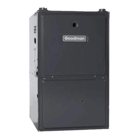
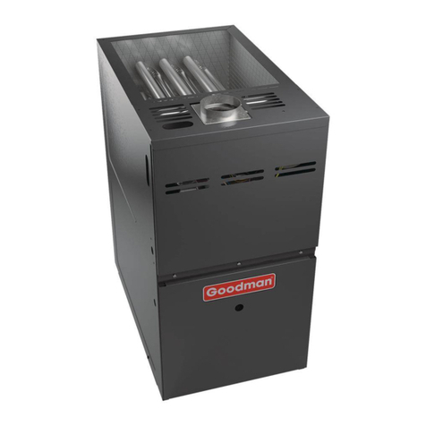
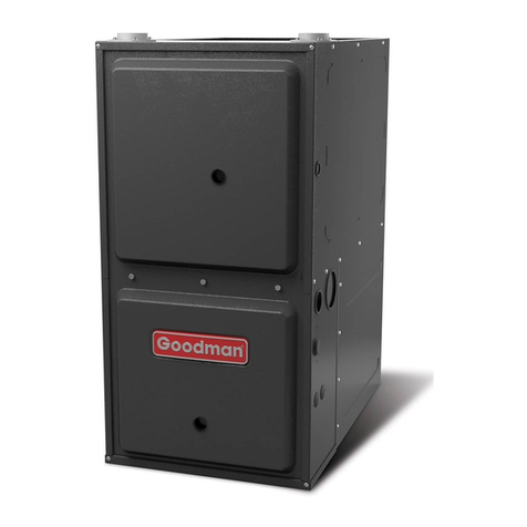
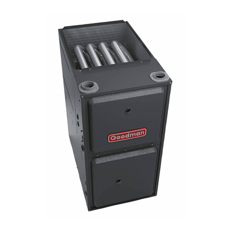
APG/GPGunits are equipped withadirect spark ignition sys-
tem. Ignition is provided by 22,000 volt electronic spark. A
flamesensorthenmonitorsforthepresenceofflameandcloses
the gas valve if flame is lost.
Thesystemmaybecontrolledby most good heatingandcool-
ing thermostats with an adjustable heat anticipator.
NOTE: Some night setback thermostats that do not have a
common terminal, use a power robbing circuit in the off cycle
tomaintainthebatteries. This type ofthermostatmayinterfere
withtheoperationof the ignitioncontrolmoduleandshould not
beused.
HEATINGSEQUENCE
In order to illustrate the heating sequence, the following has
beensimplifiedtogive a better understanding of the pressure
switchoperation.
Thefigurebelowisaviewoftheinduceddraftblowershowing
the location of the pressure tap. The induced draft blower is
mounted on the collector box, where the combustion gases
fromtheheatexchanger are drawn through the collector box.
PRESSURE TAP
COOLING
The refrigerant used in the system is R-22. It is clear, color-
less, non-toxic, non-irritating, and non-explosive liquid. The
chemicalformulaisCHCIF2. Theboiling point, at atmospheric
pressureis-41.4°F.
A few of the important principles that make the refrigeration
cyclepossibleare: heatalwaysflowsfroma warmertoacooler
body, under lower pressure a refrigerant will absorb heat and
vaporizeatalowtemperature,thevaporsmaybedrawnoffand
condensed at a higher pressure and temperature to be used
again.
Theindoorevaporator coilfunctionstocooland dehumidifythe
airconditionedspacesthroughthe evaporative processtaking
place within the coil tubes.
NOTE: Actualtemperaturesandpressuresare to beobtained
fromtheexpandedratingsintheTechnicalInformationManual.
Hightemperature,highpressurevapor leaves thecompressor
through the discharge line and enters the condenser coil. Air
drawnthroughthe condensercoilbythecondenserfancauses
therefrigeranttocondenseintoaliquidby removing heat from
therefrigerant. Astherefrigerantiscooledbelowitscondens-
ingtemperatureitbecomes subcooled.
Thesubcooledhighpressureliquidrefrigerantnowleavesthe
condenser coil via the liquid line until it reaches the indoor
expansiondevice.
As the refrigerant passes through the expansion device and
intotheevaporator coilapressuredropis experiencedcausing
therefrigeranttobecomealowpressureliquid. Lowpressure
saturated refrigerant enters the evaporator coil where heat is
absorbedfromthewarmairdrawnacrossthecoilbytheevapo-
ratorblower. Asthe refrigerant passes through the lasttubes
of the evaporator coil it becomes superheated, that is, it ab-
sorbsmoreheatthanisnecessaryfortherefrigeranttovapor-
ize. Maintainingpropersuperheatassuresthatliquidrefriger-
ant is not returning to the compressor which can lead to early
compressorfailure.
Lowpressuresuperheatedvaporleavestheevaporatorcoiland
returns through the suction line to the compressor where the
cycle begins again.
COOLING CYCLE
All Models
When the contacts of the room thermostat close, the termi-
nals R to Y and G on the control board are energized.
Thecontrolboardrecognizesthis as ademandforcoolingand
energizesthecompressorcontactorandindoorblowermotor.
Theblowerdelay is an integral part ofthecontrolboard.
When the thermostat is satisfied, it opens its contacts, break-
ing the low voltage circuit, causing the compressor contactor
to open and indoor fan to stop after a 60 second delay.
Iftheroomthermostat fan selector switch should be set to the
"on"positionthentheindoorblowerwouldruncontinuousrather
than cycling with the compressor.