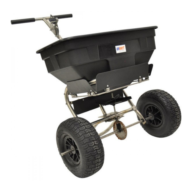
gopart FGP455400GP User manual

Walk behind drop spreader
25 L
DE
FR
NL
DK
ES
IT
PL
Handgeführter Streuwagen
Épandeur à guidage manuel
Manuele strooiwagen
Skubbespreder
Carro esparcidor por goteo
Spargitore a spinta manuale a caduta
Rozsiewacz prowadzony ręcznie
FGP455400GP

2
UK
GENERAL WARNING
READ and UNDERSTAND this manual completely before using Drop Spreader.
Operator must read and understand all safety and warning information, operating
instructions, maintenance and storage instructions before operating this equipment.
Failure to properly operate and maintain the drop spreader could result in serious in-
jury to the operator or bystanders.
Operation Warnings
• Do not at any time carry passengers sit or stand on the spreader.
• Do not allow children to play on, stand upon or climb in the spreader.
• Always inspect the spreader before using to assure it is in good working condition.
• Replace or repair damaged or worn parts immediately.
• Always check and tighten hardware and assembled parts before operation.
• Do not exceed equipment maximum load capacity of 60lb.
• Avoid large holes and ditches when operating the spreader.
• Always push the spreader do not pull the spreader.
• Be careful when operating on steep grades (hill) the spreader may tip over.
• Do not push close to creeks, ditches and public highways.
• Do not use spreader on windy days when spreading grass seed or herbicides.
• Always use caution when loading and unloading spreader.
• Never tow the spreader with a motorized vehicle.
Crush and Cut Hazards
• Always keep hands and feet clear from moving parts while operating the equipment.
• Always clear and keep work area clean and free from debris when operating.
• Always wear safety gear, eye protection, gloves and work boots when operating the
spreader.
WARNING: The warnings, cautions, and instructions outlined in this instruction manual cannot cover all possible
conditions or situations that may occur. It must be understood by the operator that common sense and caution are
factors which cannot be built into this product and must be supplied by the operator.
PROP 65 WARNING: This product contains chemicals known to the state of California to cause cancer, birth de-
fects, or other reproductive harm.
Assembly Is Required
This product requires assembly before use. See “Assembly” section for instructions.
Because of the weight and/or size of the drop spreader, it is recommended that another
adult be present to assist with the assembly. INSPECT ALL COMPONENTS closely upon
receipt to make sure no components are missing or damaged.

3
UK
HAZARD SIGNAL WORD DEFINITIONS
ABOUT YOUR DROP SPREADER
This drop spreader is designed to spreader a wide range of materials (Pesticides, Pel-
letized Lime, Fertilizer, and Grass Seed). Materials such as Powders, Manure, Top Soil,
Gravel, and Mulch have the wrong physical characteristics and should not be used with
this spreader. It is an easy and convenient way to feed or fertilize grass that is adjacent
to vegetable gardens, sidewalks, or plant beds. Drop spreaders are great at keeping
material waste to a minimum with even coverage. Never exceed the rated load capacity
of 60lbs when operating the spreader.
Your drop spreader needs to be pushed at three miles per hour, which is a brisk walk-
ing speed. Slower or faster speeds will change the spread coverage. Wet spreading
material will also change the flow rate. Clean your spreader thoroughly after each use.
Wash between the moving parts at bottom of the hopper.
Technical specifications on the drop spreader are provided in the “Specifications” sec-
tion of this manual.
This is the safety alert symbol. It is used to alert you to
potential personal injury hazards. Obey all safety
messages that follow this symbol to avoid pos-
sible injury or death.
DANGER indicates an imminently hazardous situa-
tion which, if not avoided, will result in death or
serious injury.
DANGER
WARNING indicates a potentially hazardous situa-
tion which, if not avoided, could result in death or
serious injury.
WARNING
CAUTION indicates a potentially hazardous situa-
tion which, if not avoided, may result in minor or
moderate injury.
CAUTION
CAUTION used without the safety alert symbol indi-
cates a potentially hazardous situation which, if
not avoided, may result in property damage.
CAUTION

4
UK
CONTROLS AND FEATURES IDENTIFICATION
Read this owner’s manual before operating the equipment. Familiarize yourself with
the location and function of the controls and features. Save this manual for future ref-
erence.
1
2
3
4
CAUTION: Read and follow all instructions for assembly and operation. Failure to properly assemble this equip-
ment could result in serious injury to the user or bystanders, or cause equipment damage.
DROP SPREADER COMPONENT PARTS AND ASSEMBLY
Take all parts out of the shipping crate and inspect components to ensure there are no
missing pieces before starting to assemble the drop spreader follow steps 1 through 4.
TOOLS REQUIRED
• 10mm Wrench
• Pliers
1) Flow Control Handle– Con-
trols the flow of material
being spread.
2) U-Handle – Maneuvers the
drop spreader.
3) Hopper – Do not exceed rated
load capacity 60lb.
4) Non Flat Tires / Wheels –
Heavy duty plastic.

5
UK
COMPONENT PARTS

6
UK
ASSEMBLY INSTRUCTIONS
STEP 1: Attach Wheels to Hopper Assembly
1. As per Pic. 1, assemble a Flat Washer Ø12, a Bushing, a Poly Wheel on one end of
the wheel axle, which as a Ø3 hole. Then go on assembling a Flat Washer Ø12, at
this moment, please insert a Cotter Pin Ø3X30 into the Ø3 hole on the wheel axle
and make the cotter bent for locking.
2. Assemble a Flat Washer Ø12, a Bushing, a Poly Wheel at the other end of the wheel
axle. Turn the wheel till the Ø5 hole on the wheel is in the same line with the Ø5
hole on the wheel axle, insert the Cotter Pin Ø5X45 and make it bent for locking.
Step 2: Attach Support Legs to Hopper Assembly
1. As per Pic. 3, insert two Hex Bolt M6X35 with Big Flat Washer Ø6 from the inner
hopper and a leg, then locked by two Wing Nut M6. Tighten the nuts.
2. Using the same way to assemble the other leg. See Pic.4.

7
UK
STEP 3: Attach Connect Poles to Support Legs
1. As per Pic.5, assemble a Connect Pole onto the top of leg and locked by a Carriage
Bolt M6X35 and a Wing Nut M6.
2. Use the same way to assemble the other Connect Pole. See Pic. 6.
STEP 4: Attach U-Handle to Connect Poles
1. As per Pic.7, connect the Handle with Connect Pole, locked by a Hex Bolt M6X30
and a Wing Nut M6 on the left.
2. On the right, insert the Adjustable Wire into the hole of Index plate, then assemble
the Index plate on the handle and Connect Pole by using Hex Bolt M6x30, Lock Nut
M6 and Wing Nut M6.
3. Assemble Wire Crip Bottom Plate on the Connect Pole by using Hex bolt M6x30 and
Lock Nut M6。
4. Use the Wire Grip Plate press the Adjustable Wire and Wire Crip Bottom Plate by
using Screw M5x10 and Lock Nut M5. See pic. 8.
5. Tighten all hardware before operating the drop spreader.
Note: The flow controls handle needs to be on the outside of the U-handle.

8
UK
ADJUSTING METHOD

9
UK
OPERATION INSTRUCTIONS
WARNING: Before using the drop spreader, review the instructions below and safety information before operating.
Failure to follow these instructions may result in property damage or injury to the operator or bystanders.
USING YOUR SPREADER
1. Inspect your spreader before each use. Make sure the wheels turn easily when the
spreader is pushed. The hopper should be clean and free from cracks.
2. Spreader is designed to spread a range of materials (Pesticides, Pelletized Lime,
Fertilizer, and Grass Seed). Materials such as Powder, Manure, Top Soil, Gravel,
and Mulch have the wrong physical characteristics and should not be used with
your spreader.
3. Do not use spreader on windy days when spreading grass seed or herbicides.
4. Determine approximate square footage of the area to be covered and estimate
amount of material required. Please refer to fertilizer manufacturer’s recommen-
dation. Break up any lumpy fertilizer as you fill the hopper.
5. Before filling the hopper, make sure the flow control handle is in the“0”position
and the flow control is closed.
6. Every time you are ready to stop or turn back, close the flow control to stop dis-
persing the material and continue one more stride. This reduces waste and avoids
damaging the lawn with oversaturated product coverage.
7. Follow fertilizer manufacturer’s recommended coverage rate for each product.
8. To maintain the same coverage when walking at a different speed, adjust the flow
rate. Reduce the flow setting for slower speeds and increase the flow setting for
higher speeds.
9. Keep spreader horizontal when operating. Tilting the spreader will result in un-
even coverage.
10. Always start walking prior to opening the flow control rate.
11. Always close the flow control before turning or stopping the spreader.
12. If spreading material is accidentally deposited too heavily in a small area, soak the
area thoroughly with a garden hose or sprinkler to prevent burning of the lawn.
13. Apply two header strips at each end of area to be treated and then proceed length-
wise between the header strips.
14. To insure consistent coverage, make sure each drop pattern slightly overlaps the
previous drop pattern.
15. When dropping material, make sure the material does not hit evergreen trees,
flowers or shrubs.
16. Do not over apply spreading material. Follow the recommended coverage rate for
each product. Over application will lead to lawn damage and contamination.

10
UK
OPERATION INSTRUCTIONS
ADJUSTING FLOW CONTROL
1. For proper material flow settings refer to the spreading instructions section.
2. Move the bolt on flow control assembly to the proper setting and tighten.
3. Pushing the spreader forward at a brisk walking speed to ensure consistent cover-
age of material.
4. To stop or turning, move the flow control handle to the closed position before stop-
ping or turning.
CAUTION: The spreader settings are guidelines only. The spreader should be calibrated prior to application to
ensure accuracy.
The spreader settings are based on a walking speed of 3 MPH. Walking faster or slower will alter the spread ap-
plication rate. Exact rates depend upon the spreader itself and the accuracy of the person operating it.
CONSISTENT COVERAGE
To insure consistent coverage, make sure each drop pattern slightly overlaps the previ-
ous pattern as shown in the figure below.
WARNING: Do not over apply material. Follow the recommended coverage rate for each product. Over application
will lead to damage and contamination. If spreading material accidentally hits or deposits to heavily, soak the area
thoroughly with a garden hose or sprinkler to prevent burning.

11
UK
SPREADING INSTRUCTIONS
CALCULATING AMOUNT OF MATERIAL NEEDED
To calculate the amount of fertilizer you will need to cover your lawn, divide the cover-
age amount listed on the label by the weight of the fertilizer bag. For example a 10LB.
bag of fertilizer with coverage of 10,000 square feet will distribute 1LB. of fertilizer
every 1,000 square feet at full rate or 1/2LB. of fertilizer every 1,000 square feet at half
rate. For pre-calculated rates see Chart A (Example: 25LB. bag with 15,000 sq. ft. cov-
erage = 1.7LB./1,000 sq. ft.). Use Chart B to find the closest spreader setting (Example:
1.7LB./1000 sq. ft. = Spreader Setting of 5).
LBS/1,000 SQ FT
Weight of Bag (LBS.) 5,000 SQ FT COVERAGE 10,000 SQ FT COVERAGE 15,000 SQ FT COVERAGE
5 1.0 LB. 0.5 LB. 0.3 LB.
10 2.0 LB. 1.0 LB. 0.7 LB.
15 3.0 LB. 1.5 LB. 1.0 LB.
20 4.0 LB. 2.0 LB. 1.3 LB.
25 5.0 LB. 2.5 LB. 1.7 LB.
30 6.0 LB. 3.0 LB. 2.0 LB.
35 7.0 LB. 3.5 LB. 2.3 LB.
40 8.0 LB. 4.0 LB. 2.7 LB.
45 9.0 LB. 4.5 LB. 3.0 LB.
50 10.0 LB. 5.0 LB. 3.3 LB.
*These are only estimates actual amounts may vary.
Chart A - Square Foot Coverage per Bag*
*These are only estimates actual spreader settings may vary depending on material.
Chart B – Drop Spreader Settings*
MULTI-USAG-
ES
LBS/1,000 SQ
FT
SPREADER SET-
TING
1 10
FERTILIZER 2 12
3 14
GRASS SEEDS 4 15
5 17
PESTICIDES 6 18
7 20
8 21
9 23
10 25
CAUTION
The spreader settings are guide-
lines only. The spreader should
be calibrated prior to application
to ensure accuracy.
The spreader settings are based
on a walking speed of 3 MPH.
Walking faster or slower will alter
the spread application rate. Exact
rates depend upon the spreader
itself and the accuracy of the per-
son operating it.

12
UK
MAINTENANCE AND STORAGE
WARNING: Improper maintenance and storage of the drop spreader may void your warranty.
MAINTENANCE
• After each use clean material out of hopper.
• Rinse/dry inside and outside of the spreader after each use.
• Periodically check all fasteners for tightness.
• Annually clean and lightly lubricate moving parts or as needed.
• Use a glossy enamel spray paint to touch up scratched or worn painted metal sur-
faces.
• Never exceed load capacity rating of 60lbs it will damage the spreader.
IMPORTANT: If a part needs replacement, only use parts that meet the manufacturer’s specifications. Replacement
parts that do not meet specifications may result in a safety hazard or poor operations.
STORAGE
• Never allow material to remain in the hopper for extended periods of time. Return
unused product to its original container.
• Before storing make sure the spreader is clean and dry for years of trouble free
service.
• Store indoors or protected area during severe weather and winter months.
SPECIFICATIONS
Load Capacity 60lb (27.21kg)
Spreader Type Drop
Hopper Material Polypropylene
Hopper Dimensions 23.6”x 11.6” x 9” (59.9x11.6x22.9cm)
Handle Length 34.25” (87cm)
Wheel Size 12” (30.5cm)
Net Weight 9.69lb (4.4kg)

13
UK
13
PARTS DRAWING & PARTS LIST
Ref# Description Qty Ref# Description Qty
1 Screw M5x6 8 21 Screw M5X10 2
2 Scratch Board 2 22 Index Plate Assembly 1
3 Wheel Axle 1 23 Cotter Pin Ø5X45 1
4 Hex Bolt M6X35 5 24 Nylon Lock Nut M6 4
5 Big Flat Washer Ø6 6 25 Wire Lock -1 1
6 Hopper 1 26 Wire Lock -2 1
7 Axle Bushing 2 27 Screw ST.4.8x20 1
8 Flat Washer Ø12 3 28 Carriage Bolt M6X25 1
9 Poly Wheel 2 29 Outer Teeth Washer Ø8 1
10 Cotter Pin Ø3X30 1 30 Spacer 1
11 Bushing 2 31 Adjustable Handle A 1
12 Rotating Door As-
sembly
1 32 Adjustable Handle B 1
13 Handle 1 33 Screw ST.4.2x18 1
14 Hex Bolt M6X30 4 34 Adjustable Handle Rod 1
15 Connect Pole 2 35 Nylon Washer 1
16 Carriage Bolt
M6X35
2 36 Nylon Lock Nut M5 2
17 End Cap 4 37 Lock Washer Ø6 1
18 Support Leg 2 38 Wire Crip plate 1
19 Wing Nut 9 39 Wire Crip Bottom Plate 1
20 Adjustable Wire 1

14
DE
DE
14
ALLGEMEINE WARNHINWEISE
Vor der Benutzung des Streuers müssen Sie diese Anleitung vollständig GELESEN und VERSTANDEN haben.
Vor der Benutzung dieses Geräts muss der Bediener alle Sicherheits- und Warnhinwei-
se sowie alle Anweisungen zu Bedienung, Wartung und Lagerung gelesen und verstan-
den haben. Falls der Streuer zum Schieben nicht ordnungsgemäß benutzt und gewar-
tet wird, kann dies schwere Verletzungen des Bedieners oder unbeteiligter Personen
zur Folge haben.
Warnhinweise zum Betrieb
• Befördern Sie niemals Personen sitzend oder stehend auf dem Streuer.
• Lassen Sie nicht zu, dass Kinder auf dem Streuer spielen, stehen oder auf den
Streuer klettern.
• Prüfen Sie vor der Benutzung des Streuers stets, ob dieser sich in einem einwand-
freien Zustand befindet.
• Ersetzen oder reparieren Sie beschädigte oder verschlissene Teile sofort.
• Prüfen Sie vor dem Gebrauch stets alle Befestigungsteile und montierten Bauteile,
und ziehen Sie sie fest.
• Überschreiten Sie niemals die maximale Nutzlast von 60lb.
• Vermeiden Sie große Löcher und Gräben, wenn Sie den Streuer benutzen.
• Schieben Sie den Streuer immer, ziehen Sie ihn nicht.
• Seien Sie vorsichtig, wenn Sie an steilen Hängen arbeiten, da der Streuer umkippen
kann.
• Bewegen Sie den Streuer nicht in der Nähe von Bächen, Gräben und öffentlichen
Schnellstraßen.
• Benutzen Sie den Streuer nicht an windigen Tagen, wenn Sie Grassamen oder Her-
bizide streuen.
• Gehen Sie beim Beladen und Entladen des Streuers stets umsichtig vor.
• Ziehen Sie den Streuer niemals mit einem motorisierten Fahrzeug.
Quetsch- und Schneidgefahren
• Halten Sie bei der Benutzung des Gerätes Hände und Füße stets von beweglichen
Teilen fern.
• Entfernen Sie Hindernisse aus dem Arbeitsbereich, und halten Sie den Arbeitsbe-
reich stets sauber und frei von Schmutz, wenn Sie das Gerät benutzen.
• Tragen Sie stets Sicherheitsausrüstung, Augenschutz, Handschuhe und Arbeitsstie-
fel, wenn Sie den Streuer benutzen.
WARNUNG: Die in dieser Anleitung aufgeführten Warnhinweise und Anweisungen können nicht alle möglichen
Bedingungen und Situationen abdecken. Der Bediener muss sich darüber im Klaren sein, dass gesunder Menschen-
verstand und Vorsicht Faktoren sind, die nicht in dieses Produkt integriert werden können.
PROP 65-WARNUNG: Dieses Produkt enthält Chemikalien, die nach Kenntnissen des Bundesstaats Kalifornien
(USA) Krebs, Geburtsfehler oder andere Fortpflanzungsschäden verursachen.
Montage erforderlich
Dieses Produkt muss vor der Benutzung zusammengebaut werden. Anweisungen
hierzu finden Sie im Abschnitt „Montage“. Aufgrund des Gewichts und/oder der Größe
des Streuers zum Schieben sollte bei der Montage eine weitere erwachsene Person
helfen. PRÜFEN SIE ALLE BAUTEILE bei Erhalt genau, um sicherzustellen, dass keine
Bauteile fehlen oder beschädigt sind.

15
DE
DE
WORTDEFINITIONEN GEFAHRENSYMBOLE
ALLGEMEINE HINWEISE ZU DIESEM STREUER
Dieser Streuer zum Schieben eignet sich für zahlreiche Materialien (Pestizide, Kalkgra-
nulat, Dünger und Grassamen). Materialien wie Pulver, Mist, Humus, Kies und Mulch
verfügen nicht über geeignete physikalische Eigenschaften und sollten mit diesem
Streuer nicht verwendet werden. Der Streuer bietet eine unkomplizierte, bequeme
Möglichkeit, Gras in der Nähe von Gemüsegärten, Gehwegen oder Beeten mit Nähr-
stoffen zu versorgen. Ein Streuer zum Schieben eignet sich hervorragend für eine
gleichmäßige Verteilung und wenn Materialabfall auf ein Mindestmaß reduziert werden
soll. Überschreiten Sie bei der Benutzung des Streuers niemals die Nennnutzlast von
60lbs.
Der Streuer muss mit einer Geschwindigkeit von ca. 3mph geschoben werden. Bei
einer geringeren oder höheren Geschwindigkeit ändert sich die Streuabdeckung. Der
Durchsatz ändert sich auch bei feuchtem Streumaterial. Reinigen Sie den Streuer nach
jeder Benutzung gründlich. Waschen Sie den Bereich zwischen den beweglichen Teilen
und dem Boden des Trichters.
Technische Daten zu diesem Streuer finden Sie in dieser Bedienungsanleitung im Ab-
schnitt „Technische Daten“.
Dies ist das Sicherheitswarnsymbol. Es wird verwendet,
um Sie vor möglichen Verletzungen zu warnen.
Beachten Sie alle Sicherheitshinweise, die zu
diesem Symbol gehören, um Verletzungen oder
gar tödliche Verletzungen zu verhindern.
GEFAHR weist auf eine unmittelbar drohende Ge-
fahr hin, die zum Tod oder zu schweren Verlet-
zungen führt, wenn sie nicht vermieden wird.
GEFAHR
WARNUNG weist auf eine mögliche Gefahrensituati-
on hin, die zum Tod oder zu schweren Verletzun-
gen führen kann, wenn sie nicht vermieden wird.
WARNUNG
ACHTUNG weist auf eine mögliche Gefahrensituati-
on hin, die zu mittleren bis leichten Verletzungen
führen kann, wenn sie nicht vermieden wird.
ACHTUNG
ACHTUNG weist ohne das Sicherheitswarnsymbol
auf eine mögliche Gefahrensituation hin, die zu
Sachschäden führen kann, wenn sie nicht ver-
mieden wird.
ACHTUNG

16
DE
BEDIENELEMENTE UND AUSSTATTUNGSMERKMALE
Lesen Sie diese Anleitung, bevor Sie das Gerät in Betrieb nehmen. Machen Sie sich
mit den Örtlichkeiten und den Funktionen der Bedienelemente und Merkmale vertraut.
Bewahren Sie diese Anleitung so auf, dass sie immer zum Nachschlagen verfügbar ist.
1
2
3
4
ACHTUNG: Lesen und beachten Sie alle Anweisungen zur Montage und Bedienung. Wenn dieses Gerät nicht ein-
wandfrei montiert wird, kann das zu schweren Verletzungen des Bedieners oder unbeteiligter Personen oder einer
Beschädigung des Gerätes führen.
BAUTEILE UND MONTAGE DES STREUERS ZUM SCHIEBEN
Nehmen Sie alle Teile aus der Versandverpackung. Inspizieren Sie die Bauteile, um
sicherzustellen, dass keine Teile fehlen, bevor Sie mit der Montage des Streuers zum
Schieben beginnen (Schritte1 bis 4).
ERFORDERLICHES WERKZEUG
• 10-mm-Schraubenschlüssel
• Zange
1) Bediengriff für die Durch-
satzsteuerung– Zum Regeln
des Streumaterial-Durchsat-
zes.
2) U-Griff– Zum Führen des
Streuers zum Schieben.
3) Trichter– Überschreiten Sie
nicht die Nennnutzlast von
60lbs.
4) Notlaufreifen/-räder– Kunst-
stoff, schwere Ausführung.

17
DE
BAUTEILE
Sechskantschraube
M6X30
4St.
Sechskantschraube
M6X25
4St. Schraube
M5X10
2St.
Schlossschraube
M6X35
2St.
Sicherungsmutter
M5
2St.
Sicherungsmutter
M6
2St. Hülse
2St.
Drahtplatte
1St.
Flügelmutter
M6
8St.
Unterlegscheibe
Ø12
3St.
Große Unterlegscheibe
Ø6
4St.
Splint
Ø3X30
1St.
Splint
Ø5X45
1St.
Drahtbodenplatte
1St.
Trichter
1 st
Poly-Rad
2 st
Griff
1 st
Verbindungsstange
2 st
Index-Plattengruppe
1 st
Bein
2 st

18
DE
MONTAGEANLEITUNG
SCHRITT1: Die Räder an der Trichterbaugruppe befestigen
1. Montieren Sie gemäß Abb.1 eine Unterlegscheibe Ø12, eine Buchse, ein Poly-Rad
auf der einen Seite der Radachse mit einer Bohrung Ø3. Montieren Sie eine Un-
terlegscheibe Ø12, führen Sie dann einen Splint Ø3X30 in die Bohrung Ø3 auf der
Radachse ein, und biegen Sie den Splint zur Verriegelung um.
2. Montieren Sie eine Unterlegscheibe Ø12, eine Buchse, ein Poly-Rad auf der ande-
ren Seite der Radachse. Drehen Sie das Rad, bis die Bohrung Ø5 auf dem Rad an
der Bohrung Ø5 der Radachse ausgerichtet ist, führen Sie den Splint Ø5X45 ein,
und biegen Sie ihn zur Verriegelung um.
Poly-Rad
Splint
Ø3X30
Trichter
Splint
Ø5X45
UnterlegscheibeØ12
UnterlegscheibeØ12
UnterlegscheibeØ12
Hülse
Abb. 1
Abb. 2
Schritt2: Die Stützbeine an der Trichterbaugruppe befestigen
1. Führen Sie gemäß Abb.3 zwei Sechskantschrauben M6X35 mit großer Unterleg-
scheibe Ø6 vom Trichterinneren zum Bein ein, und verriegeln Sie sie mit zwei
Flügelmuttern M6. Ziehen Sie die Muttern an.
2. Montieren Sie das zweite Bein auf dieselbe Weise. Siehe Abb.4.
Abb. 3
Abb. 4
Bein
FlügelmutterM6
Sechskantschraube
M6X35
Große Unterlegscheibe
Ø6

19
DE
SCHRITT3: Verbindungsstangen an den Stützbeinen befestigen
1. Montieren Sie gemäß Abb.5 eine Verbindungsstange auf dem Bein, und verriegeln
Sie dieses mit einer Schlossschraube M6X35 und einer Flügelmutter M6.
2. Montieren Sie die zweite Verbindungsstange auf dieselbe Weise. Siehe Abb. 6.
Schlossschraube
M6X35
Abb. 5 Abb. 6
FlügelmutterM6
Verbindungsstange
SCHRITT4: U-Griff an den Verbindungsstangen befestigen
1. Schließen Sie gemäß Abb.7 den Griff an die Verbindungsstange an, die mit einer
Sechskantschraube M6X30 und einer Flügelmutter M6 links verriegelt ist.
2. Führen Sie rechts den Einstelldraht in die Bohrung der Index-Platte ein, und mon-
tieren Sie dann die Index-Platte auf dem Griff und der Verbindungsstange. Ver-
wenden Sie dazu die Sechskantschraube M6x30, die Sicherungsmutter M6 und die
Flügelmutter M6.
3. Montieren Sie die Drahtbodenplatte mit der Sechskantschraube M6x30 und der
Sicherungsmutter M6 auf der Verbindungsstange.
4. Drücken Sie mit der Drahtplatte auf Einstelldraht und Drahtbodenplatte, verwen-
den Sie dazu die Schraube M5x10 und die Sicherungsmutter M5. Siehe Abb. 8.
5. Ziehen Sie alle Befestigungsteile an, bevor Sie den Streuer zum Schieben benut-
zen.
Hinweis: Der Bediengriff für die Durchsatzsteuerung muss sich auf der Außenseite des
U-Griffs befinden.
Abb. 7 Abb. 8
Schraube M5X10
Sicherungsmutter M5
FlügelmutterM6
Sicherungsmutter
M6
Griff
Index-Plattengruppe
Sechskantschraube
M6X30
Drahtbodenplatte
Sechskant-
schraube
M3X30

20
DE
EINSTELLVERFAHREN
1. Lösen Sie die beiden Schrauben...
3. Wenn der Griff auf 0 und die Bohrung auf
dem Trichter vollständig geschlossen ist,
ziehen Sie diese zwei Schrauben an.
5. Durch die Position der Mutter kann
der Abstand zwischen der Bohrung auf
dem Trichter und der Drehbaugruppe
verändert werden.
2. Drücken Sie diesen
Griff in die untere
Position.
4. Ziehen Sie diesen
Griff in oberste Stellung
(bei 25), stellen Sie
sicher, dass die Bohrung
auf dem Trichter
vollständig offen ist.
Table of contents
Languages:
Other gopart Spreader manuals