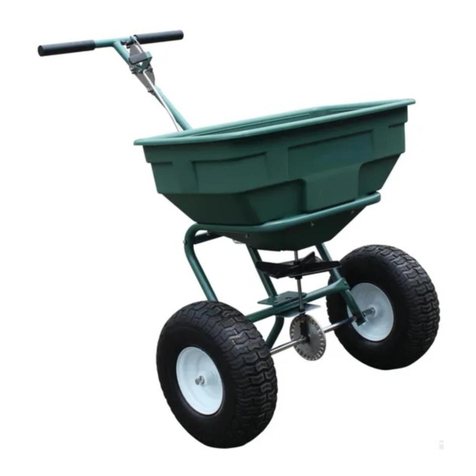
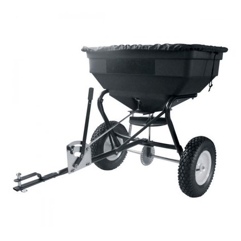
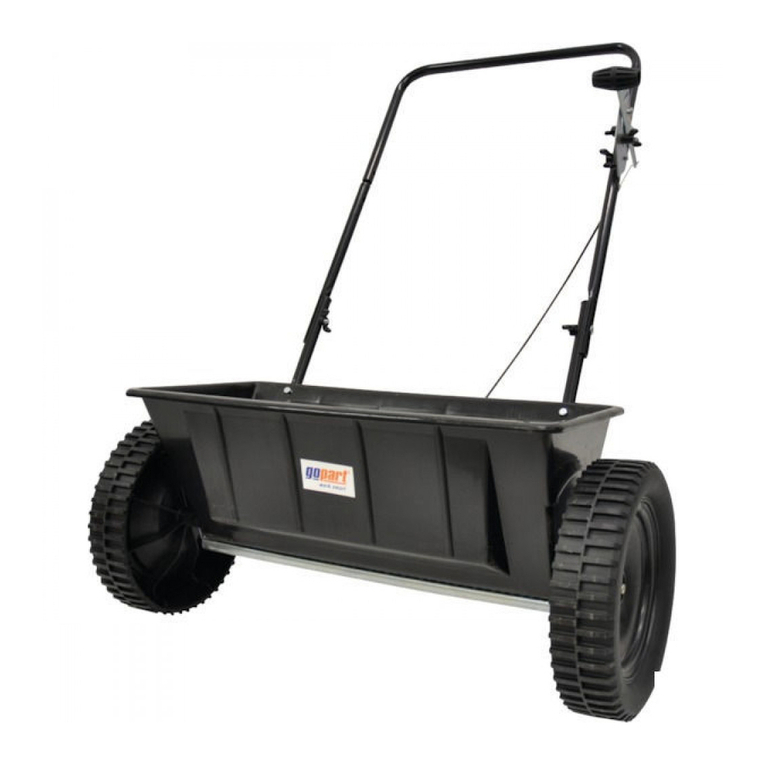
gopart FGP455600GP User manual

Salt Spreader
60L
DE
FR
NL
DK
ES
IT
PL
Salzstreuwagen
Épandeur de sel
Zoutstrooiwagen
Saltspreder
Esparcidor de sal
Spargitore di sale
Posypywarka soli
FGP455600GP

2
UK
HAZARD SIGNAL WORD DEFINITIONS
ABOUT YOUR SALT SPREADER
This salt spreader is designed to spread a wide range of materials (Rock Salt, Ice Melt,
Sand, Seed Mulch and large-size granular material). Materials such as Powders,
Manure, Top Soil, and Gravel have the wrong physical characteristics and should not be
used with this spreader. Never exceed the rated load capacity of 125lbs when operating
the spreader.
Your spreader needs to be pushed at three miles per hour, which is a brisk walking
speed. Slower or faster speeds will change the spread patterns. Wet spreading mate-
rial will also change the spread pattern and flow rate. Clean your spreader thoroughly
after each use. Wash between the shut off plate and bottom of the hopper.
Technical specifications on the push spreader are provided in the “Specifications” sec-
tion of this manual.
This is the safety alert symbol. It is used to alert you to
potential personal injury hazards. Obey all safety
messages that follow this symbol to avoid pos-
sible injury or death.
DANGER indicates an imminently hazardous situa-
tion which, if not avoided, will result in death or
serious injury.
DANGER
WARNING indicates a potentially hazardous situa-
tion which, if not avoided, could result in death or
serious injury.
WARNING
CAUTION indicates a potentially hazardous situa-
tion which, if not avoided, may result in minor or
moderate injury.
CAUTION
CAUTION used without the safety alert symbol indi-
cates a potentially hazardous situation which, if
not avoided, may result in property damage.
CAUTION

3
UK
CONTROLS AND FEATURES IDENTIFICATION
Read this owner’s manual before operating the equipment. Familiarize yourself with
the location and function of the controls and features. Save this manual for future ref-
erence.
CAUTION: Read and follow all instructions for assembly and operation. Failure to properly assemble this equip-
ment could result in serious injury to the user or bystanders, or cause equipment damage.
SALT SPREADER COMPONENT PARTS AND ASSEMBLY
Take all parts out of the packaging and inspect components to ensure there are no
missing pieces before starting to assemble the push spreader follow steps 1 through 3.
TOOLS REQUIRED
• Pliers (2 Each)
• 10mm Wrenches (2 Each)
• 13mm Wench
1 T-Handle – Pushes and moves
the spreader easily.
2 Hopper – Do not exceed rated
load capacity 125lb.
3 3-Flap Deflector Shields – Con-
trols spreading pattern around
sidewalks and near sensitive foli-
age.
4 Impeller - Evenly distributes
material.
5 Tires / Wheel – Do not exceed
recommended rated 20PSI.
6 Flow Control – Controls the flow
of material being spread.
1
2
3
4
5
6

4
UK
COMPONENT PARTS

5
UK
ASSEMBLY INSTRUCTIONS
STEP 1: Attaching the Wheels
1. When assembling the wheels make sure the air valves are facing outward.
2. Slide the wheel bushing (#19) onto the left side of the axle.
3. Push one wheel (#15) onto the axle. Align the hole in the axle and wheel and insert
the M6x60 bolt (#24) and secure with a M6 lock nut (#9).
4. Slide the other wheel bushing (#19) onto the right side of the axle.
5. Push the wheel (#15) onto the axle. Slip the Ø16 flat washer (#17) and insert the
Ø5x35 cotter pin (#16) into the hole and fasten it by bending.

6
UK
STEP 2: Attach Handle to the Supporting Leg
1. Insert handle assembly into the supporting leg (#39). In the center holes put two
M6x35 bolts (#40), Ø6 spring washer (#55) and secure with M6 lock nut (#9).
2. On the outer holes of the handle assembly and supporting leg (#39) put four M6x20
bolts (#47), Ø6 spring washers (#55) and secure with M6 lock nuts (#9).

7
UK
STEP 3: Connecting the Solid Linkage
1. Push the flow control handle to the “30” position. Insert the A end of the connect-
ing rod (#34) through the Ø8 flat washer (#12) and into the hole on the gauge level
plate (#46). Secure with a M8 lock nut (#11).
2. Insert the B end of the connecting rod (#34) through the Ø8 flat washer (#12) and
into the hole on the fixed plate (#13). Secure with M8 lock nut (#11).
3. Push the control handle to the “0” position. The hole in the bottom of the spreader
should be completely closed. If the flow control handle position and the hole in the
bottom of the hopper does match exactly, loosen the two bottom M6 lock nuts (#9)
and move the gauge level plate until the handle position and the hole in the bottom
of the hopper match. Re-tighten the two M6 lock nuts (#9).

8
UK
OPERATION INSTRUCTIONS
WARNING: Before using the push spreader, review the instructions below and safety information before operating.
Failure to follow these instructions may result in property damage or injury to the operator or bystanders.
USING YOUR SPREADER
1. Inspect your spreader before each use. Make sure the wheels turn easily, and the
gearbox moves when the spreader is pushed. The hopper should be clean and free
from cracks.
2. Spreader is designed to spread a range of materials (Rock Salt, Ice Melt, Sand,
Fertilizer and Grass Seed). Materials such as Powder, Manure, Top Soil and Gravel
have the wrong physical characteristics and should not be used with your spread-
er.
3. Determine approximate size of the area to be covered and estimate amount of ma-
terial required. Please refer to fertilizer manufacturer’s recommendation. Break
up any lumpy fertilizer as you fill the hopper.
4. Before filling the hopper, make sure that the flow control lever is in the“0”position
and the flow control plate is closed.
5. Set the adjustable stop with the flow control lever always in the“0”position. Every
time you are ready to stop or turn back, close the flow control plate to stop dis-
persing the material and continue one more stride. This reduces waste and avoids
damaging the lawn with oversaturated product coverage.
6. Follow fertilizer manufacturer’s recommended coverage rate for each product.
7. To maintain the same coverage when walking at a different speed, adjust the flow
rate. Reduce the flow setting for slower speeds and increase the flow setting for
higher speeds.
8. Keep the impeller plate horizontal when operating the spreader. Tilting the
spreader will result in uneven coverage.
9. Always start walking prior to opening the closure plate.
10. Always close the flow control plate before turning or stopping the spreader.
11. If spreading material is accidentally deposited too heavily in a small area, soak the
area thoroughly with a garden hose or sprinkler to prevent burning of the lawn.
12. To insure consistent coverage, make sure each broadcast pattern slightly overlaps
the previous broadcast pattern.
13. When broadcasting spreading material, make sure the broadcast pattern does not
hit evergreen trees, flowers or shrubs.
14. Do not over apply spreading material. Follow the recommended coverage rate for
each product. Over application will lead to lawn damage and contamination.

9
UK
OPERATION INSTRUCTIONS
CAUTION: The spreader settings are guidelines only. The spreader should be calibrated prior to application to
ensure accuracy.
The spreader settings are based on a walking speed of 3 MPH. Walking faster or slower will alter the spread ap-
plication rate. Exact rates depend upon the spreader itself and the accuracy of the person operating it.
ADJUSTING THE FLOW
1. For proper material flow settings refer to the spreading instructions section.
2. Move the bolt on flow control assembly to the proper setting and tighten.
3. Pushing the spreader forward at brisk walking speed to ensure consistent cover-
age of material.
4. To stop, move the flow control lever to the closed position before stopping.
CONSISTENT COVERAGE
To insure consistent coverage, make sure each broadcast pattern slightly overlaps
the previous broadcast pattern as shown in figures below. Your spreader comes with
adjustable deflector shields (shield down) to control the flow of Rock Salt or Ice Melt.
The approximate broadcast widths for different materials are shown in the application
chart.
WARNING: Do not over apply spreading material. Follow the recommended coverage rate for each product. Over
application will lead to damage and contamination. If spreading material accidentally hits or deposits to heavily,
soak the area thoroughly with a garden hose or sprinkler to prevent burning.

10
UK
SPREADING INSTRUCTIONS
CALCULATING AMOUNT OF MATERIAL NEEDED
To calculate the amount of fertilizer you will need to cover your lawn, divide the cover-
age amount listed on the label by the weight of the fertilizer bag. For example a 10LB.
bag of fertilizer with coverage of 10,000 square feet will distribute 1LB. of fertilizer
every 1,000 square feet at full rate or 1/2LB. of fertilizer every 1,000 square feet at half
rate. For pre-calculated rates see Chart A (Example: 25LB. bag with 15,000 sq. ft. cov-
erage = 1.7LB./1,000 sq. ft.). Use Chart B to find the closest spreader setting (Example:
1.7LB./1000 sq. ft. = Spreader Setting of 12).
LBS/1,000 SQ FT
Weight of Bag (LBS.) 5,000 SQ FT COVERAGE 10,000 SQ FT COVERAGE 15,000 SQ FT COVERAGE
5 1.0 LB. 0.5 LB. 0.3 LB.
10 2.0 LB. 1.0 LB. 0.7 LB.
15 3.0 LB. 1.5 LB. 1.0 LB.
20 4.0 LB. 2.0 LB. 1.3 LB.
25 5.0 LB. 2.5 LB. 1.7 LB.
30 6.0 LB. 3.0 LB. 2.0 LB.
35 7.0 LB. 3.5 LB. 2.3 LB.
40 8.0 LB. 4.0 LB. 2.7 LB.
45 9.0 LB. 4.5 LB. 3.0 LB.
50 10.0 LB. 5.0 LB. 3.3 LB.
*These are only estimates actual amounts may vary.
Chart A - Square Foot Coverage per Bag*
*These are only estimates actual spreader settings and spread widths may vary de-
pending on material.
Chart B - Spreader Settings/Spread Widths
MULTI- USAGES LBS/1,000
SQ FT
SPREADER
SETTING
SMALL PARTICLE
SPREAD
MEDIUM PARTICLE
SPREAD
LARGE PARTICLE
SPREAD
1 10 5-6 FT. 6-9 FT. 9-12 FT.
ROCK SALT 2 12 5-6 FT. 6-9 FT. 9-12 FT.
3 14 5-6 FT. 6-9 FT. 9-12 FT.
ICEMELT 4 15 5-6 FT. 6-9 FT. 9-12 FT.
5 17 5-6 FT. 6-9 FT. 9-12 FT.
FERTILIZER 6 18 5-6 FT. 6-9 FT. 9-12 FT.
7 20 5-6 FT. 6-9 FT. 9-12 FT.
GRASS SEEDS 8 23 5-6 FT. 6-9 FT. 9-12 FT.
9 25 5-6 FT. 6-9 FT. 9-12 FT.
10 30 5-6 FT. 6-9 FT. 9-12 FT.

11
UK
SPREADING INSTRUCTIONS
ADDITIONAL SPREADER SETTING INSTRUCTIONS
For materials that DO NOT use a typical 5,000 Sq. Ft, 10,000 Sq. Ft. & 15,000 Sq. Ft.
coverage value.
To obtain the proper spreader settings follow the steps below:
1) Find the total weight in lbs. of the product from the product label on the bag of
material.
2) Find the coverage amount in square feet that the product is rated for from the
product label on the bag of material.
3) Divide the bag weight rated in lbs. by the square feet coverage rated on the bag.
4) Take this result and multiply it by 1000.
5) This final number is the lbs. of material to be spread per 1000 square feet.
6) Use the spreader setting number in Chart B for the proper setting.
As an example:
1) The fertilizer bag weighs 10 lbs.
2) The coverage value is rated at 2000 square feet.
3) 10 lbs. / 2000 square ft. = 0.005
4) 0.005 × 1000 = 5 lbs. per 1000 sq. ft.
5) Using this number in Chart B, you would obtain a spreader setting of 17.
WARNING: Do not over apply spreading material. Follow the recommended coverage rate for each product. Over
application will lead to damage and contamination. If spreading material accidentally hits or deposits to heavily,
soak the area thoroughly with a garden hose or sprinkler to prevent burning.

12
UK
MAINTENANCE AND STORAGE
WARNING: Improper maintenance and storage of the push spreader may void your warranty.
MAINTENANCE
• • After each use clean material out of hopper.
• Rinse/dry inside and outside of the spreader after each use.
• Before operating make sure the tires have the RECOMMENDED TIRE PRESSURE
20 PSI.
• Periodically check all fasteners for tightness.
• Annually clean and lightly lubricate parts.
• Never exceed load capacity rating of 125lbs it will damage the spreader.
IMPORTANT: If a part needs replacement, only use parts that meet the manufacturer’s specifications. Replacement
parts that do not meet specifications may result in a safety hazard or poor operations.
STORAGE
• Never allow material to remain in the hopper for extended periods of time.
• Before storing make sure the spreader is clean and dry for years of trouble free
service.
• Store indoors or protected area during severe weather and winter months.
SPECIFICATIONS
Load Capacity 125lb
Spreader Type Broadcast
Hopper Material Polypropylene
Hopper Dimensions 29.5” x 16.5” x 13.4”
Overall Dimensions 43.3” x 31.5” x 38”
Wheel size 14’’
Tire Pressure (PSI) 20
Unit Weight 18.5kg

13
UK
PARTS DRAWING & PARTS LIST

14
UK
Ref# Description Qty Ref# Description Qty
1 Hopper Assembly 1 32 Gear 1
2 Ø6 Big Flat Washer 16 33 Swivel Axle Base 1
3 M6x40 Hex Bolt 17 34 Connecting Rod 1
4 Hopper Screen 1 35 M8x75 Hex Bolt 1
5 Swivel Axle Bushing 2 36 Wheel Bushing 1
6 Fixed Adjustable Plate 1 37 Fixed Crossover Tube 1
7 Active Adjustable Plate 1 38 End Cap 3
8 Base for Spring 1 39 Support Leg 1
9 M6 Lock Nut 29 40 M6x35 Hex Bolt 2
10 Spring 1 41 Handle Connecting Tube 1
11 M8 Lock Nut 3 42 Sponge Handle 2
12 Ø8 Flat Washer 2 43 Ø5x8 Rivet 2
13 Fixed Plate for Connecting
Rod
1 44 Rain Cover 1
14 Impeller 1 45 Swivel Axle Base 1
15 Pneumatic Wheel 2 46 Gauge Level Plate 1
16 Ø5x35 Cotter Pin 1 47 M6x20 Hex Bolt 7
17 Ø16 Flat Washer 3 48 M6x25 Round Head Bolt 1
18 Stainless Steel Wing Nut 6 49 Ø8 Gear Lock Washer 1
19 Wheel Bushing 2 50 Connecting Rod Plate 1
20 Inner Axle Bushing 2 51 Spacer 1
21 Outer Axle Bushing 2 52 Wing Nut 1
22 Support Frame Assembly 1 53 Adjustable Handle 1
23 Hopper Assembling Tube 1 54 Handle Grip 1
24 M6x60 Bolt 1 55 Ø6 Spring Washer 7
25 Swivel Axle 1 56 Nylon Washer 1
26 Small Gear 1 57 Rear Back Plate 1
27 Ø3x16 Spring Pin 1 58 Hanging Plate 4
28 M4x20 Screw 1 59 Side Back Plate (left and
right)
2
29 R-Pin Ø3.6x80 1 60 M6x20 Round Head Bolt 10
30 Axle 1 61 Front Back Plate 1
31 Ø4x30 Spring Pin 2 62 Hanging Rod 1

15
DE
WÖRTERDEFINITIONEN GEFAHRENSYMBOLE
ALLGEMEINE HINWEISE ZU DIESEM STREUER
Dieser Streuer eignet sich für zahlreiche Streumaterialien (Steinsalz, Streusalz, Sand,
Samen, Mulch und grobkörnigere Materialien). Materialien wie Pulver, Mist, Humus
und Kies verfügen nicht über geeignete physikalische Eigenschaften und sollten mit
diesem Streuer nicht verwendet werden. Überschreiten Sie bei der Benutzung des
Streuers niemals die Nennnutzlast von 125lbs.
Der Streuer muss mit einer Geschwindigkeit von ca. 3mph geschoben werden. Bei
einer geringeren oder höheren Geschwindigkeit ändert sich das Streumuster. Streu-
muster und Durchsatz ändern sich auch bei feuchtem Streumaterial. Reinigen Sie den
Streuer nach jeder Benutzung gründlich. Waschen Sie den Bereich zwischen Absperr-
platte und Boden des Trichters.
Technische Daten zu diesem Streuer finden Sie in dieser Bedienungsanleitung im Ab-
schnitt „Technische Daten“.
Dies ist das Sicherheitswarnsymbol. Es wird verwendet,
um Sie vor möglichen Verletzungen zu warnen.
Beachten Sie alle Sicherheitshinweise, die zu
diesem Symbol gehören, um Verletzungen oder
gar tödliche Verletzungen zu verhindern.
GEFAHR weist auf eine unmittelbar drohende Ge-
fahr hin, die zum Tod oder zu schweren Verlet-
zungen führt, wenn sie nicht vermieden wird.
GEFAHR
WARNUNG weist auf eine mögliche Gefahrensituati-
on hin, die zum Tod oder zu schweren Verletzun-
gen führen kann, wenn sie nicht vermieden wird.
WARNUNG
ACHTUNG weist auf eine mögliche Gefahrensituati-
on hin, die zu mittleren bis leichten Verletzungen
führen kann, wenn sie nicht vermieden wird.
ACHTUNG
ACHTUNG weist ohne das Sicherheitswarnsymbol
auf eine mögliche Gefahrensituation hin, die zu
Sachschäden führen kann, wenn sie nicht ver-
mieden wird.
ACHTUNG

16
DE
BEDIENELEMENTE UND AUSSTATTUNGSMERKMALE
Lesen Sie diese Anleitung, bevor Sie das Gerät in Betrieb nehmen. Machen Sie sich
mit den Örtlichkeiten und den Funktionen der Bedienelemente und Merkmale vertraut.
Bewahren Sie diese Anleitung so auf, dass sie immer zum Nachschlagen verfügbar ist.
ACHTUNG: Lesen und beachten Sie alle Anweisungen zur Montage und Bedienung. Wenn dieses Gerät nicht ein-
wandfrei montiert wird, kann das zu schweren Verletzungen des Bedieners oder unbeteiligter Personen oder einer
Beschädigung des Gerätes führen.
BAUTEILE UND MONTAGE DES SALZSTREUERS
Nehmen Sie alle Teile aus der Verpackung. Inspizieren Sie die Bauteile, um sicher-
zustellen, dass keine Teile fehlen, bevor Sie mit der Montage des Streuers beginnen
(Schritte1 bis 3).
ERFORDERLICHES WERKZEUG
• Zange (jeweils 2)
• 10-mm-Schraubenschlüssel (jeweils 2)
• 13-mm-Schraubenschlüssel
1 T-Griff– Für einfaches Führen
des Streuers.
2 Trichter– Überschreiten Sie
nicht die Nennnutzlast von
125lbs.
3 3-Klappen-Deflektor-Schutzab-
deckungen– Zur Steuerung des
Verteilmusters neben Gehwegen
und in der Nähe von wurzelemp-
findlichen Grünpflanzen.
4 Flügelrad– Verteilt das Material
gleichmäßig.
5 Reifen/Rad– Überschreiten Sie
nicht den empfohlenen Druck
von 20psi.
6 Durchsatzsteuerung– Steuert
den Durchsatz des gestreuten
Materials.
1
2
3
4
5
6

17
DE
BAUTEILE
Nr.24 Schraube
M6X60
1St.
Nr.40 Schraube
M6X35
2St.
Nr.47 Schraube
M6X20
4St.
Nr.11 Sicherungsmutter
M8
2St.
Nr.9 Sicherungsmutter
M6
7St.
Nr.19 Radbuchse
2St.
Nr.17 Unterlegscheibe
Ø16
1St.
Nr.55 Federscheibe Ø6
6St.
Nr.12 Unterlegscheibe
Ø8
2St.
Nr.16 Splint Ø5X35
1St.
Hauptbaugruppe
1 st
Regen Abdeckung
1 st Griffanordnung
1 st
Gitter
1 st
Pneumatik Rad
2 st
Verbindungsstange
1 st

18
DE
MONTAGEANLEITUNG
SCHRITT1: Räder anbringen
1. Achten Sie bei der Montage der Räder darauf, dass die Druckluftventile nach au-
ßen weisen.
2. Schieben Sie die Radbuchse (Nr.19) auf die linke Seite der Achse.
3. Drücken Sie ein Rad (Nr.15) auf die Achse. Richten Sie die Bohrung in der Achse
und im Rad aus, fügen Sie eine Schraube M6x60 ein (Nr.24), und sichern Sie diese
mit einer Sicherungsmutter M6 (Nr.9).
4. Schieben Sie die andere Radbuchse (Nr.19) auf die rechte Seite der Achse.
5. Drücken Sie das Rad (Nr.15) auf die Achse. Schieben Sie die Unterlegscheibe Ø16
auf (Nr.17), fügen Sie den Splint Ø5x35 (Nr.16) in die Bohrung ein, und sichern Sie
ihn durch Umbiegen.
Nr.24 Schraube M6X60
Nr.19 Radbuchse
Nr.17 Unterlegscheibe Ø16
Nr.16 Splint Ø5X35
Nr.19 Radbuchse
Nr.15 Luftrad
Nr.15 Luftrad
Nr.9 Sicherungsmutter M6

19
DE
Nr.47 Schraube M6X20
Nr.40 Schraube M6X35
Nr.39 Stützbein
Nr.55 Federscheibe Ø6
Nr.9 Sicherungsmutter M6
Nr.55 Federscheibe Ø6
Nr.9 Sicherungsmutter M6
SCHRITT2: Griff am Stützbein befestigen
1. Fügen Sie die Griff-Baugruppe in das Stützbein ein (Nr.39). Setzen Sie in die zen-
tralen Bohrungen zwei Schrauben M6x35 (Nr.40) und Federscheiben Ø6 (Nr.55)
ein, und befestigen Sie diese mit der Sicherungsmutter M6 (Nr.9).
2. Setzen Sie in die äußeren Bohrungen der Griff-Baugruppe und des Stützbeins
(Nr.39) vier Schrauben M6x20 (Nr.47) und Federscheiben Ø6 (Nr.55) ein, und be-
festigen Sie diese mit Sicherungsmuttern M6 (Nr.9).

20
DE
SCHRITT3: Massives Gestänge verbinden
1. Drücken Sie den Bediengriff für die Durchsatzsteuerung in die Position„30“. Füh-
ren Sie das A-Ende der Verbindungsstange (Nr.34) durch die Unterlegscheibe Ø8
(Nr.12) und in die Anzeigeniveauplatte (Nr.46). Befestigen Sie sie mit einer Siche-
rungsmutter M8 (Nr.11).
2. Führen Sie das B-Ende der Verbindungsstange (Nr.34) durch die Unterlegschei-
be Ø8 (Nr.12) und in die Befestigungsplatte (Nr.13). Befestigen Sie sie mit einer
Sicherungsmutter M8 (Nr.11).
3. Drücken Sie den Bediengriff in die Position„0“. Die Bohrung im Boden des Streu-
ers sollte vollständig geschlossen sein. Wenn die Position des Bediengriffs für die
Durchsatzsteuerung und die Bohrung im Boden des Trichters nicht exakt passen,
lösen Sie die beiden Schrauben M6 im Boden (Nr.9) und schieben die Anzeigeni-
veauplatte so lange, bis die Griffposition und die Bohrung im Boden des Trichters
korrekt ausgerichtet sind. Ziehen Sie die beiden Sicherungsmuttern M6 wieder an
(Nr.9).
Nr.13 Befestigungsplatte
Nr.11 Sicherungsmutter M8
Nr.12 Unterlegscheibe Ø8
Nr.12
Unterlegscheibe
Ø8
Nr.34 Verbindungsstange
Nr.9 Sicherungsmutter M6
Nr.11 Sicherungsmutter M8
Nr.9 Sicherungsmutter M6
Nr.46 Anzeigeniveauplatte
Nr.34 Verbindungsstange
Table of contents
Languages:
Other gopart Spreader manuals
Popular Spreader manuals by other brands

Sealey
Sealey SPB57T instruction manual

Meyer
Meyer MINI SPREADER 36000 Parts & Installation Instructions

Craftsman
Craftsman 486.24393 owner's manual

BE Ag & Industrial
BE Ag & Industrial BE-PFS G Series Assembly instructions

Agri-Fab
Agri-Fab 45-03151 owner's manual

Fisher Engineering
Fisher Engineering WB-160D Owner's manual and installation instructions

Craftsman
Craftsman 486.1992 owner's manual

Earth Way
Earth Way 2100P Estate Assembly and operating instructions

Earth Way
Earth Way FLEX-SELECT F80 Series Assembly and operating instructions

Earth Way
Earth Way 2050SU Assembly instructions

Tube-Line
Tube-Line Nitro 315RS Operator's manual

Earth Way
Earth Way 2170 operating instructions