Gopel Electronic PXI 3090 User manual

Technical Specification
PXI
/
PCI 3090
FlexRay Interfaces
User Manual Version 2.4
FlexRay™ is a registered trade mark of Daimler AG
GOEPEL electronic GmbH
Goeschwitzer Str. 58/60
D-07745 Jena
Phone: +49-3641-6896-597
Fax: +49-3641-6896-944
E-Mail: [email protected]
http://www.goepel.com
Get the total Coverage!

Issue: June 2010
© 2010 GOEPEL electronic GmbH. All rights reserved.
The software described in this manual as well as the manual itself are supplied under license and
may be used or copied only in accordance with the terms of the license.
The customer may make one copy of the software for safety purposes.
The content of the manual is subject to change without prior notice and is supplied for information
only.
Hardware and software might be modified also without prior notice due to technical progress.
In case of inaccuracies or errors appearing in this manual, GOEPEL electronic GmbH assumes
no liability or responsibility.
Without the prior written permission of GOEPEL electronic GmbH, no part of this documentation
may be transmitted, reproduced or stored in a retrieval system in any form or by any means
as well as translated into other languages (except as permitted by the license).
GOEPEL electronic GmbH is neither liable for direct damages nor consequential damages from
the company’s product applications.
Printed: 23.06.2010
All product and company names appearing in this manual are trade names or registered trade names of their respective owners.

Table of Contents
PXI 3090/ PCI 3090 – User Manual 1
1BOARD INSTALLATION..................................................1-1
1.1 HARDWARE INSTALLATION ...................................................1-1
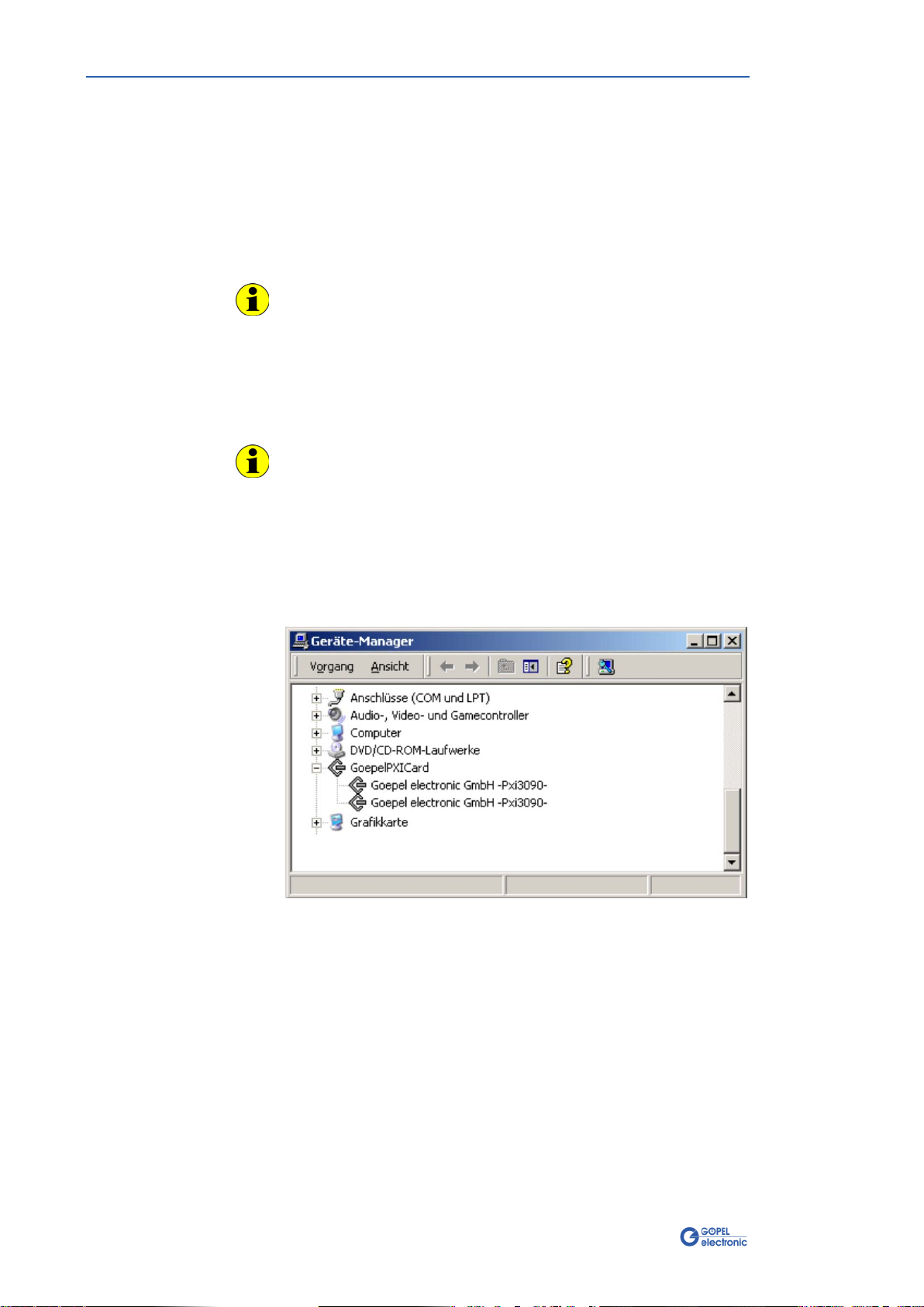
1.2 DRIVER INSTALLATION........................................................1-2
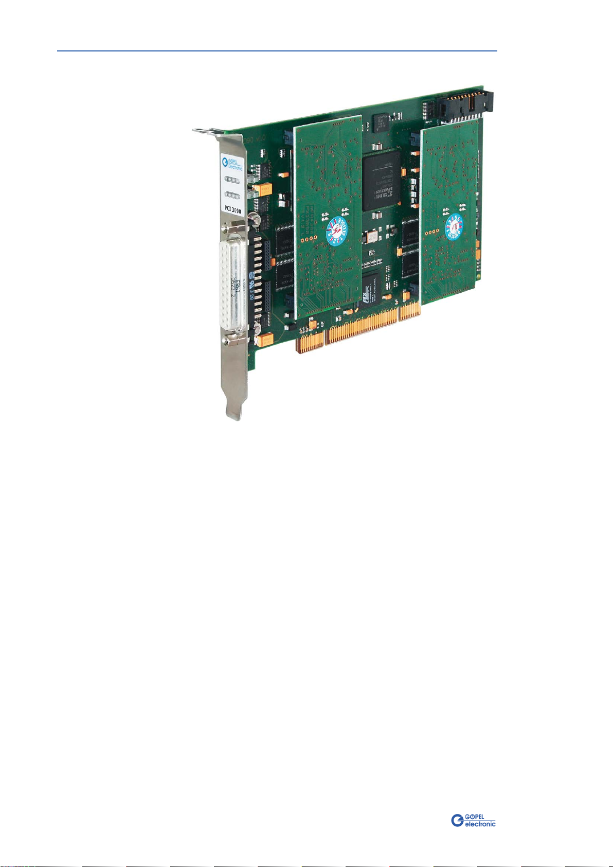
2HARDWARE ...................................................................2-1
2.1 DEFINITION .....................................................................2-1
2.2 TECHNICAL INFORMATION....................................................2-3
2.2.1
General..................................................................2-3
2.2.2
Dimensions ............................................................2-3
2.2.3
3090 Characteristics................................................2-3
2.3 CONSTRUCTION ................................................................2-4
2.3.1
General..................................................................2-4
2.3.2
Addressing.............................................................2-5
2.3.3
Communication Interfaces.......................................2-6
2.3.4
Assembly ...............................................................2-7
2.3.5
Front Connector Pinout ...........................................2-8
2.3.6
LED Indication........................................................2-9
2.4 DELIVERY NOTES...............................................................2-9
3CONTROL SOFTWARE....................................................3-1
3.1 PROGRAMMING VIA G-API...................................................3-1
3.2 PROGRAMMING VIA DLL FUNCTIONS.......................................3-1
3.2.1
Windows Device Driver ...........................................3-2
3.2.1.1 Driver Info..........................................................3-3
3.2.1.2 Write Instruction.................................................3-4
3.2.1.3 Read Response ...................................................3-5
3.2.1.4 Read Monitor......................................................3-6
3.2.1.5 XilinxReadWriteRegister.......................................3-7
3.3 PROGRAMMING WITH LABVIEW ............................................3-9
3.3.1
LabVIEW via the G-API ...........................................3-9
3.3.2
LLB using the Windows Device Driver.......................3-9
3.4 FURTHER GOEPEL SOFTWARE..............................................3-9


Installation
PXI 3090 FlexRay™ Interfaces – User Manual 1-1
1Board Installation
1.1 Hardware Installation
Please make absolutely certain that all of the installation procedures
described below are carried out with your system switched off.
The PXI™- or CompactPCI™system is to be opened according to its
conditions. A free slot is to be selected in your system.
Now, the slot cover is to be taken away from the slot selected. To do
this, unscrew the two fixation screws and remove the cover from the
slot.
(If it is necessary to exchange extension boards, pay attention to the
general rules to avoid electrostatic charging.
The modules must never be removed or mounted with the power
switched on! Additionally, the right alignment is absolutely required.)
When installing the board, touch it at its edges only.
Never touch the surface of the board, because otherwise it may be
destroyed by electrostatic charges.
Insert the board carefully into the prepared slot. Use the lever at the
front plate in order to push in the board finally.
When the board has been inserted properly, it is to be fixed by means
of the two screws at the front plate. Now, the board has been
installed correctly.
Afterwards, carry out the operations required at the system to make it
ready for operation anew.

Installation
1-2 PXI 3090 FlexRay™ Interfaces – User Manual
1.2 Driver Installation
Due to the plug and play capability of Windows®2000/ XP, for every
newly recognized hardware component a driver installation is started
automatically via the hardware assistant. The hardware assistant can
carry out the installation of the device driver by using the
inf
file
contained on the enclosed CD.
It is not absolutely essential to restart the system.
At present, the available device driver only supports
Windows®2000/ XP systems.
If you want to create your own software for the boards, you possibly
need additional files for user specific programming (
*.LLB
,
*.H
).
These files are not automatically copied to the computer and have to
be transferred individually from the supplied CD to your development
directory.
The I/O base address is generated during the boot operation of the
system and is written into the configuration area of the board.
A manual setting is not necessary.
After driver installation, you can check whether the boards are
properly imbedded by the system.
The following figure show the successful imbedding of two PXI 3090
boards:
Figure 1-1:
Display of Device Manager

Hardware
PXI 3090/ PCI 3090 – User Manual 2-1
2Hardware
2.1 Definition
FlexRay controller boards PXI/ PCI 3090 are communication boards of
GOEPEL electronic GmbH.
These boards can be used in general control technology, especially for
applications in automotive technology.
A PXI/ PCI 3090 board in the maximum construction stage offers the
following resources:
♦2 Independent FlexRay nodes
♦2 Independent CAN nodes
♦2 x Digital Input
♦2 x Digital Output
In this User Manual, Controller ALWAYS means the microcontroller
assigned to a FlexRay interface (type Infineon TC1796, µC, 150 MHz
in Figure 2-3), with the exception of the “FlexRay Controller”
designation on the front panel for the entire board).
Figure 2-1:
PXI 3090

Hardware
2-2 PXI 3090/ PCI 3090– User Manual
Figure 2-2:
PCI 3090

Hardware
PXI 3090/ PCI 3090 – User Manual 2-3
2.2 Technical Information
The PXI 3090 communication board is a plug-in board developed for
the PXI™bus (PCI eXtensions for Instrumentation). Basis of this bus
is the CompactPCI™bus.
The board can be plugged into any desired slot of a CompactPCI™or
PXI™system (except for slot 1). It can be definitely identified also in
the case that several boards of this type are used in the same rack.
The board does not have jumpers for hardware detection and is
automatically integrated into the respective system.
The PCI 3090 communication board is a PC plug-in board for the PCI
Local Bus Rev. 2.2.
It can be operated at any PCI slot (32 bits, 33 MHz, 3.3 V)
Both boards do not have jumpers for hardware detection and are
automatically integrated into the respective system.
The dimensions of the board correspond to standard dimensions of
the accompanying bus system:
♦PXI 3090 FlexRay Interface Board: 160 mm x 100 mm (L x W)
♦PCI 3090 FlexRay Interface Board: 168 mm x 106 mm (L x W)
Symbol Parameter Min. Typ. Max. Unit Remarks
VBAT Battery voltage 12 30 V Acc. to transceiver’s type
Transmission rate FlexRay 10 MBaud
Transmission rate CAN 1 MBaud
Rbus Terminating resistors 120 Ohm
Vin Input voltage 3.0 5.5 V Digital input
Vout Output voltage 5 V Digital output
2.2.1 General
2.2.2
Dimensions
2.2.3 3090
Characteristics

Hardware
2-4 PXI 3090/ PCI 3090– User Manual
2.3 Construction
In the basis version, PXI 3090/ PCI 3090 boards have two FlexRay
interfaces, extendable by two CAN interfaces of version 2.0b.
Figure 2-3 shows schematically the construction of the PXI 3090
board in a block diagram.
An ASIC is used as the interface to the PCI or cPCI bus on the
PXI/ PCI 3090 boards. It includes all the function blocks required for the
communication with the computer bus.
The PCI 3090 communication board does not have a PXI interface.
To exchange trigger signals with other GOEPEL electronic PCI boards
despite of that, there is an additional connector on the board with
eight freely configurable lines (TriggerIO in Figure 2-5).
Figure 2-3: Block diagram of a PXI 3090 Communication board
Extension Board 1 FlexRay node 1 with Communication Controller
and Transceivers for Channel A and Channel B of Node 1
Extension Board 2 FlexRay node 2 with Communication Controller and Transceivers
and Transceivers for Channel A and Channel B of Node 2
2.3.1 General

Hardware
PXI 3090/ PCI 3090 – User Manual 2-5
PXI 3090: PXI racks do have an own geographical slot addressing of
the backplane.
Numbering starts with 1and can be seen at the cover’s front side.
Mount always an embedded controller or an MXI card at slot 1.
PCI 3090: PCI racks do not have an own geographical slot addressing.
There is a separate address jumper field (Address jumper in Figure
2-5) for clear identification of the board (analogously to “geographical
addressing” of the PXI specification) in a system with several PCI
3090 boards.You can select up to 16 addressing variants by this. The
corresponding binary value (0..15) set with the jumpers can be read
out by the delivered software.
2.3.2 Addressing

Hardware
2-6 PXI 3090/ PCI 3090– User Manual
2 x FlexRay Nodes (Protocol Specification V2.1):
Both FlexRay nodes are designed as pluggable Extension boards.
The Freescale MFR4310 (FlexRay system Protocol Specification V2.1A)
is used as communication controller.
Each Extension Board has two transceivers of NXP TJA1080 type.
These transceivers realize the bus levels for Channel A and Channel B.
By the modular construction upgrades to higher protocol specifications
are possible at any time if necessary.
2 x CAN Interfaces Version 2.0b:
The CAN interfaces on a PXI/ PCI 3090 board can only be used as
highspeed interfaces.
The 120 Ohm bus terminating resistor for each CAN interface is
mounted on the board.
The type of the mounted transceiver is decisive for proper operation
of a CAN interface in a network. Often CAN networks do only
operate properly in the case that all members use a compatible type
of transceiver.
To offer maximal flexibility to the users of PXI/ PCI 3090 boards, the
transceivers are designed as plug-in modules.
There are several types that can be easily exchanged:
♦TJA1041A
♦PCA82C251
These CAN transceivers require a connection to the battery voltage
(which is provided onboard as +12V).
In the case a higher battery voltage is needed (max. +27V), that can
be supplied via the pins 18 or 12 of connector XS1 (V_Bat1..V_Bat2,
see Front Connector Pinout).
2.3.3 Commu-
nication Interfaces

Hardware
PXI 3090/ PCI 3090 – User Manual 2-7
Figure 2-4 shows schematically the component side of a PXI 3090
board. You can see the positions of the extension boards and
connectors.
C100
C200
Extension board 1
Extension board 2
XS 1
Figure 2-4: Component side of a PXI 3090 communication board (schematically)
XS 1
CAN2
CAN1
Extension board 2
Extension board 1
TriggerIO
Address
jumper 1
Figure 2-5: Component side of a PCI 3090 communication board (schematically)
Extension board 1 FlexRay node 1 with communication controller and transceivers
Extension board 2 FlexRay node 2 with communication controller and transceivers
CAN1, CAN2 Positions for pluggable CAN transceivers
2.3.4 Assembly

Hardware
2-8 PXI 3090/ PCI 3090– User Manual
Type: DSub 25 poles socket
The FlexRay interfaces are provided via this connector at the frontal
edge of the PXI 3090 communication board.
No. XS1 pin Signal name Remarks
1 1 FlexRay1A_BP FlexRay node 1 (plus bus line channel A)
2 14 FlexRay1A_BM FlexRay node 1 (minus bus line channel A)
3 2 GND Ground potential transceiver
4 15 FlexRay1B_BP FlexRay node 1 (plus bus line channel B)
5 3 FlexRay1B_BM FlexRay node 1 (minus bus line channel B)
6 16 GND Ground potential transceiver
7 4 CAN1_H CAN node 1 (High)
8 17 CAN1_L CAN node 1 (Low)
9 5 GND Ground potential transceiver
10 18 VBAT1 Reference potential transceiver (node 1)
11 6 INPUT1 Digital input FlexRay node 1
12 19 OUTPUT1 Digital output FlexRay node 1
13 7 n.c. Not assigned
14 20 FlexRay2A_BP FlexRay node 2 (plus bus line channel A)
15 8 FlexRay2A_BM FlexRay node 2 (minus bus line channel A)
16 21 GND Ground potential transceiver
17 9 FlexRay2B_BP FlexRay node 2 (plus bus line channel B)
18 22 FlexRay2B_BM FlexRay node 2 (minus bus line channel B)
19 10 GND Ground potential transceiver
20 23 CAN2_H CAN node 2 (High)
21 11 CAN2_L CAN node 2 (Low)
22 24 GND Ground potential transceiver
23 12 VBAT2 Reference potential transceiver (node 2)
24 25 INPUT2 Digital input FlexRay node 2
25 13 OUTPUT2 Digital output FlexRay node 2
At present, the CAN functions are not software supported.
2.3.5 Front
Connector Pinout

Hardware
PXI 3090/ PCI 3090 – User Manual 2-9
The LEDs arranged at the front panel indicate the current operating
state of the microcontrollers assigned to each FlexRay interface.
1
2
3
4
5
6
7
8
The LEDs indicate the following states (different for PXI/ PCI 3090!):
2.4 Delivery Notes
PXI/ PCI3090 boards are delivered in the following basic variant:
♦2x FlexRay node
2.3.6 LED
Indication
Figure 2-6:
LED Indication
State Notes
LED 1 LED 2 LED 3 LED 4 LED 5..8 PXI 3090
LED 1 LED 3 LED 5 LED 7 LED 2,4,6,8 PCI 3090
Permanently ON
not used
µC 1: Controller not running
Alternately
blinking µC 1: Bootloader software runs
Error cause (probably):
Software reset not executed
OFF µC 1: Firmware runs
ON
(shortly) OFF µC 1: Firmware runs executing
commands
Permanently ON µC 2: Controller not running
Alternately blinking µC 2: Bootloader software runs
Error cause (probably):
Software reset not executed
OFF µC 2: Firmware runs
ON
(shortly) OFF µC 2: Firmware runs executing
commands


Control Software
PXI 3090/ PCI 3090 – User Manual 3-1
3Control Software
There are three ways to integrate PXI 3090/ PCI 3090 hardware in your
own applications:
♦Programming via G-API
♦Programming via DLL Functions
♦Programming with LabVIEW
3.1 Programming via G-API
The G_API (GOEPEL-API) is the favored user interface for this
GOEPEL hardware.
You can find all necessary information in the
G-API
folder of the
delivered CD.
3.2 Programming via DLL
Functions
Programming via DLL Functions is possible also in future for existing
projects which can not be processed with the GOEPEL electronic
programming interface G-API.
We would be pleased to send the GOEPEL Firmware documentation to
you on your request.
Please get in touch with our sales department in case you need that.
For the used structures, data types and error codes, please refer to
the headers – you find the corresponding files on the supplied CD.

Control Software
3-2 PXI 3090/ PCI 3090 – User Manual
The DLL functions for programming using the Windows device driver
are described in the following sections:
♦Driver Info
♦Write Instruction
♦Read Response
♦Read Monitor
♦XilinxReadWriteRegister
The following type definitions are used:
S32 – signed long
U8 – unsigned char
U16 – unsigned short
U32 – unsigned long
3.2.1 Windows
Device Driver

Control Software
PXI 3090/ PCI 3090 – User Manual 3-3
The Pxi3090__DriverInfo function is for the status query of the
hardware driver.
Format:
S32 Pxi3090__DriverInfo(t_Driver_Info *pDriverInfo, U32 Length)
Parameters:
Pointer, for example pDriverInfo
to a data structure
For the structure, see the
Pxi3090_UserInterface.h
file on the
supplied CD
Length
Size of the storage area DriverInfo is pointing to, in bytes
Description:
The Pxi3090__DriverInfo function returns information regarding the
status of the hardware driver.
For this reason, the address of a pDriverInfo pointer has to be
transferred to the function.
The structure pDriverInfo is pointing to is filled with various
information within the function.
3.2.1.1
Driver Info

Control Software
3-4 PXI 3090/ PCI 3090 – User Manual
The Pxi3090__WriteInstruction is for sending a command to the
selected PXI 3090/ PCI 3090 controller.
Format:
S32 Pxi3090__WriteInstruction(U8 *pData, U16 DataLength)
Parameters:
Pointer, for example pData
to the write data area
consisting of Command Header and Command Bytes
(currently max. 4096 bytes per command)
DataLength
Size of the storage area pData is pointing to, in bytes
Description:
The Pxi3090__WriteInstruction function sends a command to the
PXI 3090/ PCI 3090 controller.
In the header of the structure pData is pointing to, there is the
information regarding the PXI 3090/ PCI 3090 board and the
corresponding controller to be activated by this function.
Therefore these parameters are not to be given separately.
The general structure is described in the General Firmware Notes
section of the GOEPEL Firmware documentation.
3.2.1.2
Write
Instruction
This manual suits for next models
1
Table of contents
Other Gopel Electronic Recording Equipment manuals