STEP 1
Connecting the cables
►Connect the IP Sensor to the Ethernet network
(by straight cable to the Switch, crossover cable
to the PC).
►Connect the supply adapter to the mains and
connect it to the IP Sensor power supply port.
►The green LED will light up in the RJ45 port.
►If the Ethernet connection is working properly,
the LINK (yellow) LED should light up a little
while later and switch o during data transfer to
the Ethernet (Activity signalling).
►The yellow LINK LED signals communication
with the DHCP server by ashing rapidly
STEP 2
Congure the device’s network parameters
►IP address / HTTP Port (80 as standard).
►Your network’s mask.
►Your network’s Gateway IP address.
►The name of the device (optional).
Save these settings by clicking on Apply Changes.
Resetting the device to the default settings
►Press and hold down the RESET button, and
connect the power supply.
►Hold the button for another 5 seconds until all
the diodes come on.
STEP 3
DEVICE WEBSITE
Options for opening the web page:
►Enter the device’s IP address in a browser
window.
►Click on the underlined IP address in the HWg-
Cong application.
The WWW page shows information about the input and
sensor status.
STEP 4
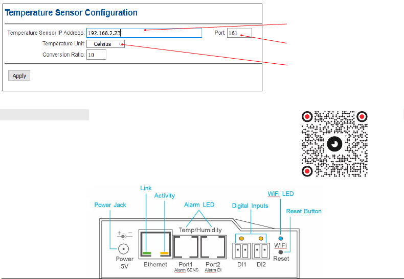
Description of ports
►Ethernet – Used to plug in a cable for an Ether-
net Internet connection for operation in a clas-
sic computer network and to congure a Wi-Fi
connection. This is a PoE (Power over Ethernet)
port for taking power from a computer network.
►Temp/Humidity – Used to plug in temperature or
humidity sensors. The sensor cable length may
be up to 60 meters for each port.
►Power – A port for connecting a 5V power supply
if powered by an external adapter.
►Digital inputs - Used to connect sensors with a
dry contact (relay) output.
Indicator lights on the front panel
►Link – A green LED signalling connectivity to a
computer network.
►Activity
– A yellow LED signalling communica-
tion in progress through a cable connection to a
computer network when ashing.
►Alarm LED – Two LEDs hidden in Port1 and
Port2. These LEDs signal Alarm status when on.
►Alarm SENS – Signals Alarm status on one of
the temperature or humidity sensors when on.
►Alarm DI – Signals Alarm status on one of the
digital inputs when on.
►Reset button
- Resets the device to
the default
settings
QUICK START GUIDE
IP SENSOR
92261/XX
RADIO TIMING®, LEDI®, LEDICA®, HANDI®are trademarks by GORGY TIMING.
Gorgy Timing RC74B38 - Any technical, aesthetic, color modications can be made without notice.
Number of statement for training provider activity : 82 38 04877 38
QUICKSTART-Sonde-IP-6009V2.0
GORGY TIMING SAS
Quartier Beauregard
38350 La Mure d'Isère (Grenoble France)
Phone: +33 4 76 30 48 20 Fax: +33 4 76 30 85 33
Alimentation
Jack
Activité
LED d’alarme Entrées digitales
LED Wi-Fi
Bouton Reset
IMPORTANT SAFETY INSTRUCTIONS
The device must not be used in particular if:
►It is visible damaged
►It does not work properly
►There are loose parts inside the device
►It was exposed to long term humidity or got wet.
WARNING! Read the section that follows very carefully
before installing your equipment. It gives the safety instruc-
tions to follow during installation.
The electrical installation to which the equipment is connec-
ted must comply with the NF C 15-100 standard.
In Europe: to comply with European regulations on the
protection of persons and the environment, you must dis-
pose of this equipment in a collection site provided for this
purpose (separately from household waste). Contact your
reseller, collection site or the competent lcoal authorities for
more information.
Modifying or opening the product without the consent of
the Customer service department will void the warranty.
All maintenance operation shall be conducted with power
shut o, including systems connected on relay outputs if
any.
Generally, the power cable (220V) and transmission cable
(of time signal) shall not be very close to each other, so as to
avoid interference (keep the distance of a few centimeters).
Gorgy Timing disclaims all responsibility in case of accident
or damage caused by an improper use of the product.
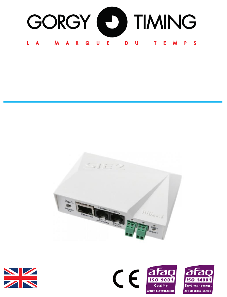
Enter the IP address of the
sensor
Enter the sensor port (161 by
default)
USER MANUAL
Find user manual of the product:
►By directly visiting http://www.gorgy-timing.co.uk/202-users-manual.htm
►By scanning the QR code
Select Temperature unit