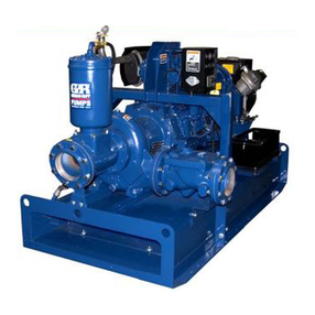
GORMAN-RUPP PUMPS 6500 Series Application guide
Other GORMAN-RUPP PUMPS Water Pump manuals

GORMAN-RUPP PUMPS
GORMAN-RUPP PUMPS PRIME-AIRE Series Operating instructions
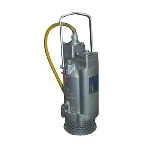
GORMAN-RUPP PUMPS
GORMAN-RUPP PUMPS S Series Application guide

GORMAN-RUPP PUMPS
GORMAN-RUPP PUMPS Super T T4B65S-B User manual

GORMAN-RUPP PUMPS
GORMAN-RUPP PUMPS PA8E60-4045H FT4 Application guide
GORMAN-RUPP PUMPS
GORMAN-RUPP PUMPS 2D-E.50 3P Application guide
GORMAN-RUPP PUMPS
GORMAN-RUPP PUMPS SUPER T T4A60S-4LE2T FT4 Series Application guide
GORMAN-RUPP PUMPS
GORMAN-RUPP PUMPS T6A65S-F4L Application guide
GORMAN-RUPP PUMPS
GORMAN-RUPP PUMPS 62 1/2A1-CH13 Series Application guide

GORMAN-RUPP PUMPS
GORMAN-RUPP PUMPS 03B31-B Application guide
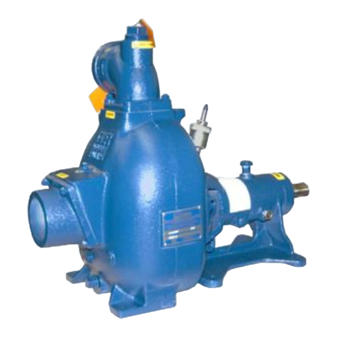
GORMAN-RUPP PUMPS
GORMAN-RUPP PUMPS 83B2-B Application guide
GORMAN-RUPP PUMPS
GORMAN-RUPP PUMPS T3A60S-B User manual

GORMAN-RUPP PUMPS
GORMAN-RUPP PUMPS T SERIES User manual
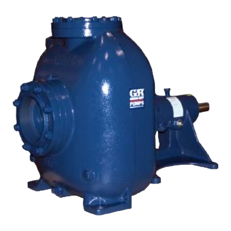
GORMAN-RUPP PUMPS
GORMAN-RUPP PUMPS 86A3-B Application guide
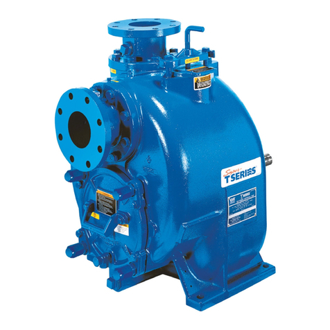
GORMAN-RUPP PUMPS
GORMAN-RUPP PUMPS T4A60S-B User manual
GORMAN-RUPP PUMPS
GORMAN-RUPP PUMPS T2C60SC-E3 Application guide
GORMAN-RUPP PUMPS
GORMAN-RUPP PUMPS 02D3-E1 1P User manual
GORMAN-RUPP PUMPS
GORMAN-RUPP PUMPS SF6B Application guide

GORMAN-RUPP PUMPS
GORMAN-RUPP PUMPS PA Series Application guide

GORMAN-RUPP PUMPS
GORMAN-RUPP PUMPS 86A52-B Application guide

GORMAN-RUPP PUMPS
GORMAN-RUPP PUMPS 11 1/2A9-B Application guide
Popular Water Pump manuals by other brands

DUROMAX
DUROMAX XP WX Series user manual

BRINKMANN PUMPS
BRINKMANN PUMPS SBF550 operating instructions

Franklin Electric
Franklin Electric IPS Installation & operation manual

Xylem
Xylem e-1532 Series instruction manual

Milton Roy
Milton Roy PRIMEROYAL instruction manual

STA-RITE
STA-RITE ST33APP owner's manual

