Goudsmit Neoflux SECF Series User manual

User Manual
Quick-cleaning Neoflux® cleanflow magnet,
series SECF
Suited for removal of ferromagnetic parts out of powders and granulates
Not suited for badly flowing (sticky) products
The descriptions and pictures in this manual, used for explanation, may differ from your machine.
We have enclosed the as-built drawing of the delivered machine.
GOUDSMIT Magnetic Systems B.V.
P.O. box 18 5580 AA Waalre
Petunialaan 19 5582 HA Waalre
The Netherlands
Tel.: (+31) (0)40 221 32 83
Internet: www.goudsmitmagnets.com
E-mail: info@goudsmitmagnets.com

Disclaimer
2
Disclaimer
© Copyright 2019, Goudsmit Magnetics Group B.V.
All rights reserved.
This manual is protected by copyright.
It is prohibited to copy any content, images or other components it contains.
This manual may not be duplicated in any manner, except with the prior written permission of Goudsmit
Magnetics Group B.V.
Revision history
Version
Date
Description
1.0
09-2004
First version of the English version of the user manual.
1.1
10-2006
1. Revisions page added.
2. All types of SECF clean flows gathered in this general user manual.
3. Remarks regarding ATEX versions added (pages 7, 8, 9, 12, 19 and 22)
1.2
06-2008
Chapter Trouble shooting changed
2.0
08-2009
Specification sheet and declaration by the manufacturer separated from manual
2.1
12-2009
CE sign removed from front page and CE remark added to id. Plate on page 7
3.0
01-2019
General update.

Introduction
3
Introduction
Read this manual and make sure that you fully
understand its contents before commissioning and
operating the machine.
If you have any queries or require further explanation
regarding any subject related to the machine, please
do not hesitate to contact GOUDSMIT Magnetic
Systems B.V.
All technical information contained in this manual,
together with any relevant drawings and technical
descriptions we supply, remain our property. It may
not be duplicated or disclosed without our prior written
permission.
The user manual can be ordered together with the
device description and/or the article number as well as
the order number (ORxxxxxx).
This manual and the declaration by the manufacturer
are part of the machine.
They must remain with the machine, even if it is sold.
The manual must be made available to all operators,
service technicians, and others who work with the
machine throughout its life cycle.

Table of contents
4
Table of contents
Disclaimer .................................................................................................................................................................................2
Revision history........................................................................................................................................................................2
Introduction...............................................................................................................................................................................3
Table of contents ......................................................................................................................................................................4
General ......................................................................................................................................................................................5
Working principle..................................................................................................................................................................5
Terms and conditions of sale and warranty...........................................................................................................................6
Delivery......................................................................................................................................................................................7
General ................................................................................................................................................................................7
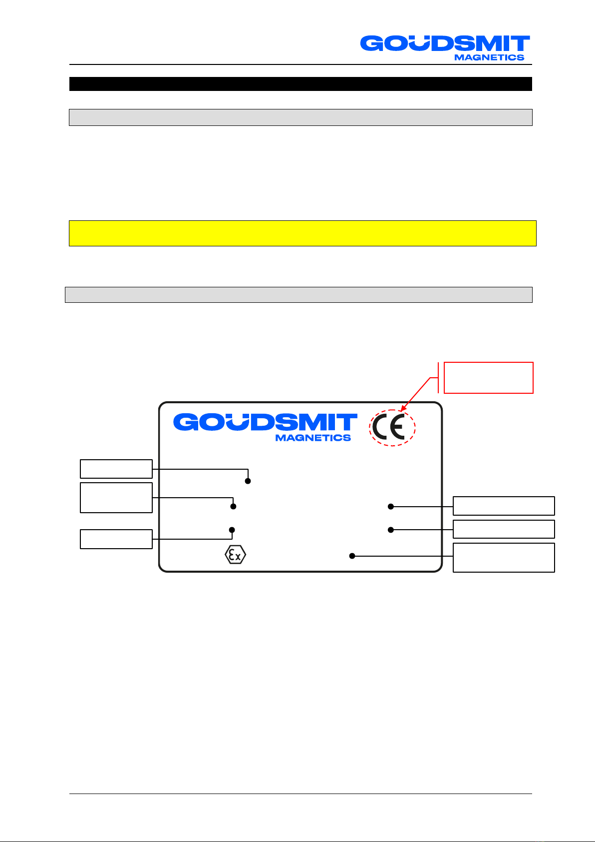
Identification plate ................................................................................................................................................................7
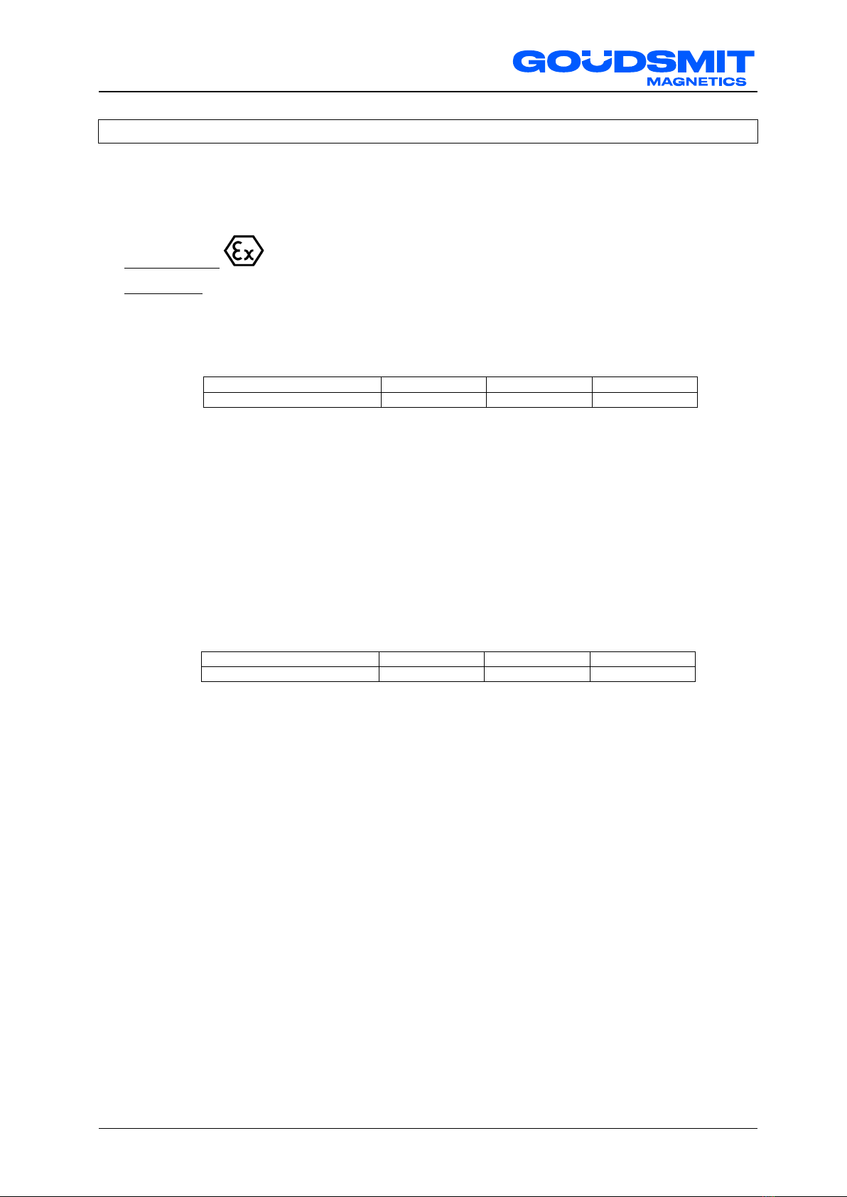
ATEX Markings (if applicable) ........................................................................................................................................8
ATEX explosive zone measures .....................................................................................................................................9
Safety.......................................................................................................................................................................................10
General ..............................................................................................................................................................................10
Danger of dust explosion ....................................................................................................................................................10
Danger of magnetic field.....................................................................................................................................................10
Separator specifications ........................................................................................................................................................12
Intended use / user indications ...........................................................................................................................................12
Separator specifications .....................................................................................................................................................13
Working principle................................................................................................................................................................14
Construction .......................................................................................................................................................................15
Magnet bar cleaning / Fe disposal ......................................................................................................................................17
Installation...............................................................................................................................................................................18
Transport and placing procedures ......................................................................................................................................18
Magnet bar protection.........................................................................................................................................................19
Gasket material / grounding................................................................................................................................................19
Electrical connections & EX .........................................................................................................................................19
Start-up....................................................................................................................................................................................20
Maintenance............................................................................................................................................................................21
Magnet bars .......................................................................................................................................................................21
Cleaning & ATEX................................................................................................................................................................21
Malfunctions/Service..............................................................................................................................................................22
Spare parts..............................................................................................................................................................................23
Storage and Dismantling........................................................................................................................................................24

General
5
General
This user manual contains information for the correct functioning and maintenance of your magnetic
device. It also contains instructions for avoiding possible injury and serious damage and allowing a safe
and as trouble-free functioning of the product as possible. Read this manual thoroughly before putting
the device into operation, familiarise yourself with the operation and control of the device and follow all
instructions precisely.
•The data published in this instruction manual are based on the available information at the time of
delivery. This is issued subject to later amendment.
•We retain the right to amend or modify the construction and/or model of our products at any time
whatsoever without any obligation to modify any previously supplied products accordingly.
Working principle
The filter contains magnetic bars, which can capture particles which have the feature "Ferro-magnetic".
For instance iron, cobalt, nickel (and their alloys) have this feature.
Exception on this rule is austenitic steel, which will lose this feature after physical deformation (for
instance by a mechanical process), or some stainless steel alloys like AISI1304 or AISI1316.

General
6
Terms and conditions of sale and warranty
The terms and conditions of sale are the ‘General conditions for the supply and erection of
mechanical, electrical and electronic products’(SE01), published by Orgalime in Brussels.
You can request a copy of these terms and conditions by writing to Goudsmit Magnetic Systems B.V., as
mentioned in our written quotation.
The aforementioned document also contains the warranty terms and conditions.
The warranty on your equipment will be void if:
•Service and maintenance are not performed in accordance with the instruction manual or are
performed by personnel who are not specially trained to do so.
Goudsmit Magnetic Systems B.V. recommends that service and maintenance be performed by
Goudsmit service technicians.
•Modifications are made to the equipment without our prior written permission.
•Parts are replaced with non-OEM or non-identical replacement parts.
•Lubrication products other than those prescribed are used.
•The equipment is used injudiciously, incorrectly, negligently or not in accordance with its intent
and/or purpose (see section ‘Intended use’).
All parts that are subject to wear are excluded from warranty!
Other remarks/warnings:
•Do not use the machine when it is damaged.
•Only use the device for the application it has been designed for.
(see section ‘Intended use’)
•Make sure all protective guards or inspection covers (including all safety circuits) have been
fitted and are installed correctly.
•Make sure the machine is maintained correctly and in accordance with the instructions
provided in this manual.
Correct any fault, especially if it can affect safety, before operating the machine.
If you decide to continue using the machine with the fault after you have performed a risk
assessment, alert the operators and maintenance personnel to the fault and the possible risks.

Delivery
7
Delivery
General
Check the shipment immediately on delivery for:
•Possible damage and/or shortcomings as a result of transport.
If damaged, ask the carrier to provide a transport damage report.
•Completeness of the delivery. Make sure nothing is missing, particularly anything extra you may
have ordered.
Always immediately contact GOUDSMIT Magnetic Systems B.V. in the event of any damage or
mistaken delivery.
Identification plate
On the device you will find an identification plate as pictured below.
Information on this plate is of great importance when service is required.
We therefore recommend that this plate never be removed.
Keep it clean and legible!
Product key: xxxx-x-xxxx-xxx-x-xx-xxx-x-x
Part no.:
Serial no.:
II 1/2D c T120°C
0344
www.goudsmitmagnets.com
Weight:
Year:
Always provide the serial number and identification number when ordering replacement parts or
service.
Only of application in
ATEX executions
Year of production
Device weight [kg]
EX code example
(if ordered)
Product key
Identification
number
Serial number

Delivery
8
ATEX Markings (if applicable)
When the equipment is suitable for use in potentially explosive atmospheres (ATEX) the type plate will
feature an Ex Marking specifying the specific device category and other criteria that the equipment
satisfies.
•Code example: II 1/2D c T120°C Da/Db
•Explanation:
II explosion group (I is underground mining, II is other)
1/2D Equipment Category (Ignition protection level: 1 = very high, 2 = high, 3 = normal)
1D inside device / 2D outside device
c Type of Ex protection
c = constructional safety
t = protection by enclosure
h = non-electrical equipment (protection method not specified further)
T120°C Maximum surface temperature
Da/Db Equipment Protection Level (EPL).
EPL
Da
Db
Dc
Suited for ATEX zone(s)
20 (21, & 22)
21 (22)
22
Da inside device / Db outside device
Ta Ambient temperature range; only displayed when the range deviates from the standard
temperature range for ATEX of -20 … +40°C
If the device is externally certified, then the ATEX certificate number is added to the type plate. Next to
the CE mark the identification number of the Notified Body that certified our ATEX quality assurance
system is displayed.
In case the equipment contains no ‘own ignition sources’ and therefore is not under scope of the ATEX
Directive, then the equipment will not get an EX marking and wil be supplied with a Statement of
Exclusion, in which this is stated and also the EX zones are listed in which it can be safely used.
Equipment category
1D
2D
3D
Suited for ATEX zone(s)
20 (21, & 22)
21 (22)
22

Delivery
9
ATEX explosive zone measures
•If the device has been ordered for use in a potentially explosive area, make sure that no higher
surface temperature arises then permitted by ATEX.
The ATEX marking on the Goudsmit identification plate only applies to the product produced by
Goudsmit Magnetic Systems B.V.
•The ATEX certified magnetic device requires additional purchase parts to be certified to the ATEX
Directive. This includes control units, connection box(es), switch(es), sensor(s) and pneumatic
parts, etc. Make sure that these are fitted by qualified personnel!
•If the device is placed in storage or has a longer standstill, make sure the device is emptied and
cleaned.
•The device must be grounded, if a gasket is used between the device and the larger installation.
Attach a metal strip between the housing of the device and the installation, to make sure the device
is grounded.
•All screw connections inside the device must be secured against loosening.
The ATEX purchase parts are provided with their own ATEX markings.
Make sure no particles > 10 mm are present in the product flow.
These can damage the magnet or extractor bars or cause impact sparks.
If necessary install a mechanical filter (sieve) before the separating equipment!

Safety
10
Safety
Regularly check that all warning pictograms are still present and legible, and clean if necessary.
Make sure that new pictograms are applied at their correct locations if they have been lost or
damaged.
General
The device is provided with safeguards where necessary. Make sure every person who comes in contact
with the device, wears adequate personal protection (overalls, safety glasses, hearing protectors, helmet,
steel-toed safety shoes etc.).
Areas of the device considered dangerous are marked with warning pictograms.
If the device remains easily accessible to persons, then extra safety precautions (e.g. fencing) must be
installed. When safeguards are not possible, make sure clear instructions are given to people using the
device.
Danger of dust explosion
If this device is made according to an EX dust category (1D/2D/3D, acc. to ATEX equipment directive
2014/34/EU) it can accordingly be used in a dust zone (20/21/22, acc. to ATEX workplace Directive
99/92/EC). The Ex category is then described on the identification plate.
Make sure that the device complies to the correct explosion category.
Danger – dust explosion!
(no sticker on device)
Also check if the identification plates of mounted parts show the correct Ex-category for the Ex
zone in which the device will be used.
Danger of magnetic field
The magnets generate a powerful magnetic field that strongly attracts ferromagnetic (Fe) materials.
Always take into account that these materials may suddenly be powerfully drawn towards the magnet.
This applies to steel workbenches and steel tools, as well as ferromagnetic materials carried on your
person, such as coins in your wallet or your keys. Use non-magnetic tools and workbenches fitted with a
wooden worktop and preferably a non-Fe frame (e.g. stainless steel) whenever possible.
Remember that ferromagnetic items, including personal items, will be attracted - even personal
items if you are closer than 0.3 metres to a magnet.
Danger - strong magnetic field!
!
!

Safety
11
People fitted with pacemakers should never enter the magnetic field
(within a radius of at least one metre).
Prohibited for people with pacemakers!
Credit cards, chip cards, computer disks/tapes, computer screens, watches
etc. may be damaged or destroyed if they enter the magnetic field
(within a radius of at least 0.5 metre).
Danger for magnetic cards!
!
!

Separator specifications
12
Separator specifications
Intended use / user indications
Products
•Suited for separating ferromagnetic* (Fe) particles out of free falling powder and granular product
streams, grain size up to 10 mm, such as plastics, flour, sugar, coffee beans, etc.
•Not suited for fatty powders or raw materials with particle size over 10 mm.
Fe particles
•Suited for use in product streams with Fe particles of 30 µm and larger, dependant on magnet type.
See product specs for exact values.
•Product stream has to be free from Fe or other parts that can cause damage to the magnet bar
tubes (like dents/bumps)
Temperatures
•Suited for surrounding temperatures of -20°C up to +40°C and
•Suited for product temperature range of -40°C up to +80°C or wider, dependant on magnet type.
See product specifications for exact values.
The magnet is to be protected against higher temperatures than prescribed, because the magnet might
lose magnetic force permanently when exposed to high temperatures
Free space
Make sure that there is approximately 0.5 meter of free space around the clean flow magnet to perform
and ease the inspection and maintenance operation, like mounting or dismounting the magnet bars.
Air pressure
The (relative) over pressure in the product channel has to be less than 0.2 bar.
The (relative) under pressure in the product channel has to be less than 0.5 bar.
Noise level
---
Vibrations
The magnet is to be protected against strong external vibrations, because the magnet might lose
magnetic force permanently and or the brittle ceramic magnet material might break.

Separator specifications
13
Cleaning
Minimum 2x per day cleaning (Fe disposal) of the device is advised for an optimal magnetic Fe
separation and to prevent Fe accumulation on the magnet bars and the problems that can be caused by
that. Clean magnets have the best Fe separation result. So, make sure to clean more often than
assumed to be necessary, to achieve a satisfactory result of the magnet device.
Clean more often when necessary and less often when proven possible!
For dirt cleaning, see chapter Maintenance.
Separator specifications
High temperatures
When high temperatures occur, there is the possibility to use other magnet material than the (standard)
applied Neoflux® or Ferroxdure magnetic material.
Abrasive products
If you have an abrasive product, we can apply a protective coating such as tungsten carbide to the
magnetic bars and/or inside housing.
Please contact us for more information.
Use in food product flows
As standard, the SECF is delivered with a 3µm ceramic blasted (NON-food) finish.
On request this can be adapted so the Cleanflow can be used in almost any food flow.
The Cleanflow separator has got the product channel (SS AISI316) almost 100% magnetically covered.
The product channel (or even complete housing + magnetic bars) can be delivered in gap-free
SS AISI304 or AISI316 or in combination with other food-improved materials, such as those prescribed
or delivered by the customer.
Surface treatments like polishing, electrolytic polishing and wet blasting can be ordered from the factory.
ATEX
The standard clean flow magnets SECF are ATEX II 1/2D executed, suited for use in dust explosive
atmospheres zone 20 inside, zoned 21 outside.
It is however your own responsibility to take the right precautions when using the SECF in dust explosive
atmospheres, like in-time cleaning to prevent for thick accumulating dust layers, and suitable grounding
measures.
Read this manual thoroughly for all ATEX measures.

Separator specifications
14
Working principle
Drawing:Cleanflow SECF
•The SECF manual cleaning Cleanflow magnet is designed to separate Fe (ferromagnetic*) parts out
of a product stream falling through the Cleanflow magnet.
•In the product channel 1 or more magnet bar layers are placed. When more layers, the layers are
placed over another in a way that the material stream passes the bars like in a cascade. The product
stream will therefore always pass minimum 1 magnet bar very closely.
•The Fe particles in the product stream will be attracted by the magnets and will "cling" onto the
tubes, while the cleaned material streams further.
•The Fe parts will stay on the tubes until it will be removed manually. This can be done by taking out
the magnet unit (Fe out) and executing a cleaning / Fe disposal action.
Unfortunately, product that gets stuck in-between and under separated Fe parts will fall off with it while
cleaning the magnet bars of Fe parts, and thus cause some "material loss".
Before every cleaning / Fe disposal cycle, the product stream has to be interrupted.
For an extra description of the cleaning / Fe disposal process:
Also see chapter Magnet bar cleaning / Fe disposal.
Magnet bar
Product stream IN
Product stream OUT
Fe OUT

Separator specifications
15
Construction
Photo: construction of Neoflux® extractor type SECF (other types: see next page)
•The standard SECF has flanges with bolt holes for easy mounting in your product channel.
Other couplings can also be ordered.
•The SECF has 1 or more layers of magnet bars. When more layers, the layers are placed over
another in a way that the product passes the bars like in a cascade.
The product will therefore always pass minimum 1 magnet bar very closely.
•The magnet bars consist of a magnet package with bushes, a magnet package in a surrounding SS
tube, or a magnet package in a surrounding SS tube in a SS extractor tube – the extractor type.
The tube versions are waterproof.
•If the magnet device is an extractor type, then the magnet bars and SS tubes are each welded to an
end plate, which means that the extractor tubes and magnet bars can be shoved in and out of one
another as complete units.
•The assembled magnet bar unit can be shoved into the product channel through the hatch opening.
•The hatch can be tightened and held dust-closed by the fasteners and the mounted door rubber
band.
Fastener clamp
Extractor tubes
Hatch opening
Door rubber
Product channel
Upper flange
Magnet bars in tubes
Bottom flange
End plate

Separator specifications
16
Photo: construction of Neoflux® (Neodymium) non-extractor type Cleanflow SECF
Photo: construction of Ferroxdure (ferrite) non-extractor type Cleanflow SECF
Fastener clamp
Hatch opening
Gasket
Product channel
Magnet bars
Bottom flange
Upper flange
Screw fastener
Gasket
Magnetic bars
Upper flange
Bottom flange

Separator specifications
17
Magnet bar cleaning / Fe disposal
Minimum 2x per day cleaning (Fe disposal) of the device is advised for an optimal magnetic Fe
separation and to prevent Fe accumulation on the magnet bars and the problems that can be caused by
that. Clean magnets have the best Fe separation result. So, make sure to clean more often than
assumed to be necessary, to achieve a satisfactory result of the magnet device.
Clean more often when necessary and less often when proven possible !
For dirt cleaning, see chapter Maintenance.
Pay attention to personal dangers / wear protective clothing, glasses, shoes and hand gloves:
Photo: Cleaning of Cleanflow SECF
Cleaning order of extractor type SECF
1. Stop the product stream.
2. Loosen the door fasteners.
3. Shove the assembly of magnet bars + extractor tubes out of the housing.
4. Shove the magnet bar unit out of the extractor tube unit.
•Catch the Fe parts that now will fall off the tubes.
•Place the magnet bar unit far enough away from the extractor tube unit on a clean surface.
5. Wipe clean with a brush of soft cloth and or blow clean the extractor tubes (not in the direction of or
over the magnet bars!).
6. Clean the magnet bars and or inside extractor tubes when necessary (with a soft cloth or a suitable
cleaning fluid).
7. Shove back the magnet bar unit into the extractor tube unit; make sure that no (new) dirt gets
trapped in-between the bars and tubes!
8. Shove the assembly of magnet bars and extractor tubes back into the housing.
9. Tighten the door fasteners.
10. (Re-)Start the product stream.
Cleaning order of non-extractor type SECF
1. Stop the product stream.
2. Loosen the door fasteners and take away the hatch when it is a loose hatch.
3. Shove the magnet bar unit out of the housing.
4. Place the magnet bar unit far enough away from the housing on a clean surface.
5. Wipe the Fe off with a brush or soft cloth and after that blow clean the magnet bars when necessary.
6. Shove back the magnet bar unit into the housing.
7. Place the hatch when it is a loose hatch (not fixed to the magnet bar unit).
8. Tighten the door fasteners, so that the hatch closes the housing dust-tight.
9. (Re-)Start the product stream.
Take out magnets

Installation
18
Installation
Transport and placing procedures
•Bolt a lifting lug to each of the 4 corners of the top flange of the magnet housing for stable lifting and
further transport. Keep each corner at the same level for proper alignment before installation. Pay
attention to possible unequal weight distribution.
Drawing: SECF lifting and transport
•Use proper lifting devices that are suitable for the device’s weight.
The weight of the device is stated on the identification plate.
•Clear the area under the magnet during lifting and transport.
•Mount the flanges of the device tightly to the inlet and outlet flange of your product channel. Improper
alignment and loose assembly may cause leakage of raw product.
•Ensure that the product channels are strong enough to support the weight of the clean flow magnet
and raw product in it. Reinforce them when necessary.
•Install the Cleanflow magnet SECF in a well reachable height for the operators. A good height eases
the working and cleaning process.
•Work safely; make sure there is enough working space, use proper scaffolding, ladders and other
help materials, so the device can be installed without safety risks.
Mount lifting belts at 4 lifting lugs.
Mount lifting lugs at 4 corner flange holes

Installation
19
Magnet bar protection
•The Cleanflow SECF has fragile tubes or bushes around the magnet material for protection. These
tubes and bushes have a small wall thickness, which ensures an optimal grade of Fe separation.
Disadvantage is however, that large, heavy Fe and or other particles in the product flow can create
bumps in the tubes and bushes, and consequently damage the magnet material underneath.
Ensure that large, heavy parts are filtered out of your product flow before it passes the Cleanflow!
Advise: place a sieve (filter) in front of the clean flow!
Also see chapter Maintenance.
Damage to the magnet bars and/or damage caused by damaged bars is not covered by guarantee.
Gasket material / grounding
To prevent the build-up of static electricity, make sure there is metal bridge between the magnetic device
/ product channel and the installation. The completed installation must also be grounded.
Electrical connections & EX
If the device is placed in an Ex zone, everything you add or change to the device's electrical installation
must be executed and documented according to the regulations for the specific Ex zone.

Start-up
20
Start-up
Before start-up, make sure that:
•The device or the installation has no damages or malfunctions.
•All connections (electrical, mechanical, pneumatic) have been made properly.
•The device or the installation is placed and situated correctly.
•All protective covers (if applicable) have been fitted correctly.
•That all objects larger than 10mm are blocked from entering the product channel.
•The device is thoroughly cleaned, internally and externally.
•The product does not fall into the magnet device, from a greater height than 10 meters.
•There are no other sources of danger present.
During start-up, make sure that:
•The device or the installation has no damages or malfunctions.
•All other parts of the device or installation function as described.
Table of contents
Other Goudsmit Industrial Equipment manuals