Goudsmit SECR-H Series Manual

GOUDSMIT Magnetic Systems B.V.
P.O. box 18, 5580 AA Waalre +31 (0)40 221 32 83
Petunialaan 19, 5582 HA Waalre www.goudsmitmagnets.com
The Netherlands info@goudsmitmagnets.com
Installation and maintenance manual
Rotary Cleanflow magnet – semi-automatic cleaning –
serie SECR-H (Hydrohansu)
Magnetic separator with permanent magnet

2 Hydrohansu – 11/2022 – v2.2
Disclaimer
© Copyright 2022 Goudsmit Magnetic Systems B.V.
All rights reserved.
Version history
Version Date Description
1.0 03/2017 First version
2.0 05/2022 New updated version
2.1 10/2022
Description counter flanges changed
Description installation of the device updated regarding barred air channel
2.2 11/2022 Section Cleaning instructions changed
Preface
This manual contains information for the correct installation and maintenance of the device. The manual contains
instructions to prevent possible injury and serious damage and ensure the safe and trouble-free operation of the
device. Please read this manual thoroughly and make sure you have understood everything before installing and
using the device in your installation.
The information published in this manual is based on the information available at the time of delivery.
We reserve the right to change or modify the construction and/or model of our products at any time, without any
obligation to modify previously delivered products accordingly.
If you need more information or if there are any questions, please contact GOUDSMIT Magnetics. The contact
details are mentioned on the title page of this document.
The manual can be ordered additionally by giving the device description and/or the article number as well as the
order number.
The descriptions and illustrations in this manual, used for explanation, can deviate from the descriptions and
illustrations of your model. The as-built drawing(s) of the delivered device are enclosed.
In this manual the rotating Cleanflow magnet, type Hydrohansu is further referred to as "device".
•
This manual and the manufacturer's declaration(s) are to be considered as part of the device.
•
The documents must remain with the device when it is sold.
•
The manual must be available throughout the life of the device to all operating personnel,
service technicians and others who work on the device.

Hydrohansu – 11/2022 – v2.2 3
Table of contents
Disclaimer........................................................................................................................................................................................2
Version history.................................................................................................................................................................................2
Preface............................................................................................................................................................................................2
Table of contents .............................................................................................................................................................................3
Safety ..............................................................................................................................................................................................4
General safety instructions ....................................................................................................................................................................4
In case of emergency ............................................................................................................................................................................4
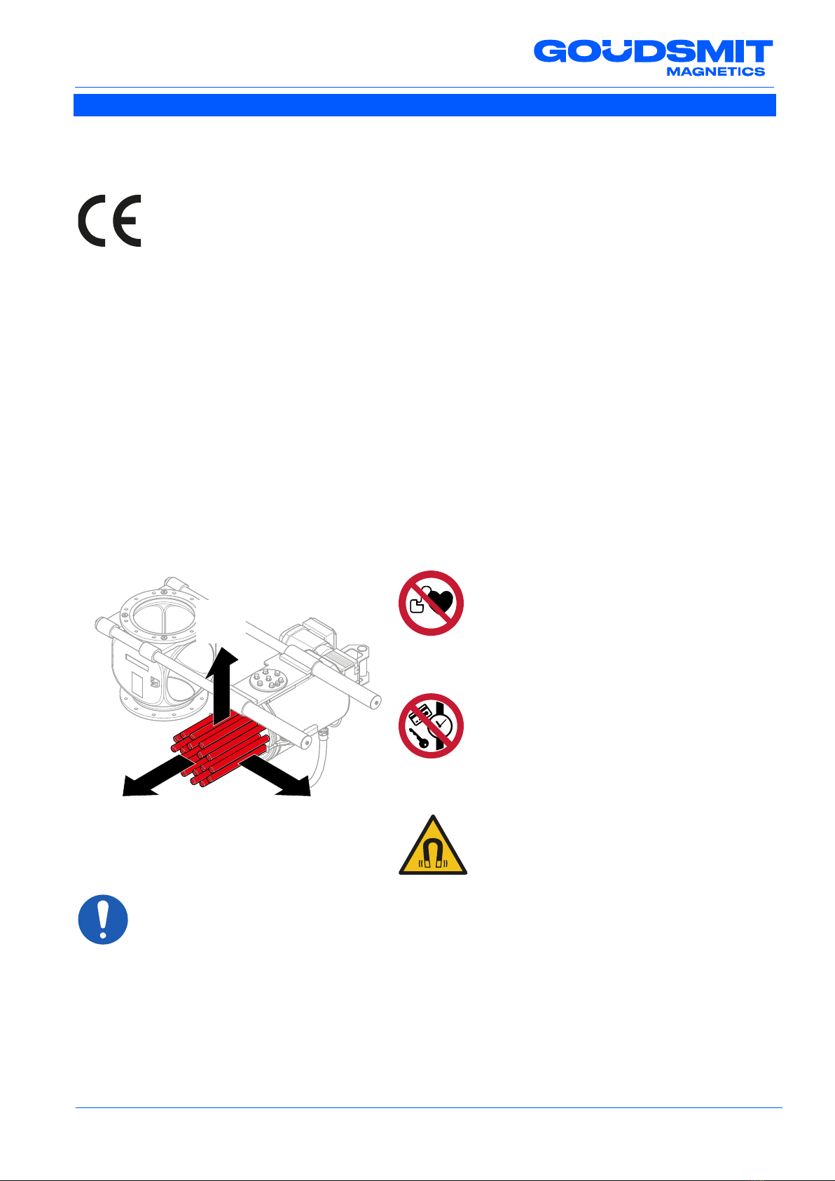
Damage by magnetic field .....................................................................................................................................................................4
Product Standards and Directives ...................................................................................................................................................5
CE marking............................................................................................................................................................................................5
Directives ..............................................................................................................................................................................................5
Occupational and public exposure limit values for (electro) magnetic fields ...........................................................................................5
General information .........................................................................................................................................................................6
Warranty conditions for previously delivered devices without a corresponding control unit.....................................................................6
Notes.....................................................................................................................................................................................................6
Specifications ..................................................................................................................................................................................7
Design ...................................................................................................................................................................................................7
Function description ..............................................................................................................................................................................7
Scope of application ..............................................................................................................................................................................7
Food contact application – use in food flows..........................................................................................................................................7
Temperatures ........................................................................................................................................................................................7
Supply voltage.......................................................................................................................................................................................7
Air pressure ...........................................................................................................................................................................................8
Nitrogen.................................................................................................................................................................................................8
Air quality ..............................................................................................................................................................................................8
Air purge on seal (air purity requirements) ........................................................................................................................................8
Compressed air ................................................................................................................................................................................8
ATEX...............................................................................................................................................................................................9
Markings................................................................................................................................................................................................9
Description of the ATEX options ..........................................................................................................................................................10
ATEX measures ..................................................................................................................................................................................10
Device overview ..................................................................................................................................................................................11
Scope of delivery .................................................................................................................................................................................11
Identification plate................................................................................................................................................................................12
Endurance test ....................................................................................................................................................................................12
Accessories .........................................................................................................................................................................................12
Transport and installation ..............................................................................................................................................................13
Transport.............................................................................................................................................................................................13
Installation of the device ......................................................................................................................................................................13
Preventing electrostatic discharge .......................................................................................................................................................14
Working principle...........................................................................................................................................................................15
Maintenance and inspection ..........................................................................................................................................................16
Cleaning instructions ...........................................................................................................................................................................16
Cleaning of the magnetic bar tubes.................................................................................................................................................17
Cleaning the O-ring with housing ....................................................................................................................................................18
Flux density measurement of the magnetic bars ..................................................................................................................................19
Sensor adjustment “magnetic bars in cleaning mode”..........................................................................................................................20
Control box ....................................................................................................................................................................................21
Malfunctions ..................................................................................................................................................................................22
Service, storage and disassembly .................................................................................................................................................23
Customer service.................................................................................................................................................................................23
Spare parts..........................................................................................................................................................................................23
Storage and disassembly (recycle) ......................................................................................................................................................23

4 Hydrohansu – 11/2022 – v2.2
Safety
This chapter describes the safety risks of the device. Where necessary, warning pictograms are attached to the
device. This chapter explains the meaning of these pictograms.
Know your decals
•
Carefully read the warnings and instructions on the decals of the device.
•
Regularly check if the decals on the device are still present, intact and clearly legible.
•
Keep the decals clean.
•Replace missing or illegible decals with new ones and make sure to put them in the same place.
General safety instructions
•The instructions in this manual must be observed. If not, material damage, physical harm or life threatening
situations may occur.
•The device is designed for the magnetic filtration of small amounts of ferrous contamination from poorly
flowing food and pharmaceutical powders with a high risk of bacterial growth. Any other use is not in
accordance with the regulations. The manufacturer's warranty does not cover any damage resulting from
such use.
•The device is equipped with safety and shielding devices. Make sure all personnel working with or in the
direct vicinity of the device are wearing sufficient safety equipment. Always leave all safely and shielding
devices at their original location when it is not necessary to remove them.
•Take extra safety precautions when the device is still easily accessible for personnel. If this is not possible,
make sure clear instructions are given about the installation if which the device is a part.
•Danger of crushing! Do not clean or do any maintenance work while the device is still running.
•All work on the device must only be done by qualified personnel. Maintenance of the magnetic bars should
preferably be done by Goudsmit personnel.
•Always apply local safely and environmental regulations.
In case of emergency
Switch off in case of emergency
The device does NOT have a safety switch. It is very important your installation has the possibility
to switch off the electrical and air supply to the device in case of emergency.
Damage by magnetic field
The magnets create a strong magnetic field that attracts ferromagnetic parts. Always use none ferromagnetic
tools and work benches with a wooden counter top and a none ferromagnetic base. Do not bring any other
ferromagnetic items, such as keys, coins and tools, into the magnetic field as they can be forcefully attracted by
the magnet, which can cause serious damage.
Strong magnetic field
During maintenance and measuring checks of the magnet components of the magnetic bars,
injuries can occur. Make sure your fingers cannot get caught between the components.

Hydrohansu – 11/2022 – v2.2 5
Product Standards and Directives
CE marking
This device complies with all the European and national requirements for construction and operation.
The CE mark confirms the compliance of the device with all applicable EU regulations,
which are associated with the application of this mark.
Directives
The standard version of this device complies with the requirements of these European Directives:
– Machinery Directive 2006/42/EC
– EMC Directive 2014/30/EU
– ATEX Directive 2014/34/EU.
Occupational and public exposure limit values for (electro) magnetic fields
The limit values of magnetic fields are defined by the EMV-guideline 2013/35/EU as follows:
Directive 2013/35/EU of the European Parliament and of the Council of 26 June 2013 on minimum health and
safety requirements regarding the exposure of workers to the risks arising from electromagnetic fields.
Observe the following measures regarding exposure to magnetic fields according to EN12198-1 (machine
category = 0, no restrictions) of the device:
Life danger for persons with
implanted medical devices
Persons with active implanted medical
devices (i.e. pacemaker, defibrillator,
insulin pump) must not enter within a
radius "R" of 250 mm from the device.
Damage to magnet sensitive objects
Objects which contain ferromagnetic parts,
such as bank, credit or chip cards, keys
and watches can be irreparably damaged
when they come within a radius “R” of
95 mm from the device.
Pregnant personnel should keep a minimal
distance of 40 mm from the magnetic bars.
Occupational exposure limit values (general
and for limbs) are not exceeded.
RR
R

6 Hydrohansu – 11/2022 – v2.2
General information
Warranty conditions for previously delivered devices without a corresponding control
unit
The following conditions apply to claims under the guarantee for devices delivered without a corresponding
control unit:
•The external control is connected to the device according to the electrical diagrams supplied by Goudsmit
Magnetics and the instruction manual "Functional Description Control System Hydrohansu".
•The device has only been in operation with an excess pressure of at least 0.5 to max. 1.0 bar on the labyrinth
seal in relation to the maximum pressure in the product channel.
All parts subject to wear and tear are excluded from the guarantee.
Notes
Do not use the device if it is damaged.
Only use the device for the application it was designed for.
Check that all protective covers (including all safety circuits) are correctly fitted and installed.
Make sure that the device is maintained correctly and in accordance with the instructions in this manual.
Eliminate any faults before operating the device. If the equipment with the fault is put into operation after you
have carried out a risk assessment, warn the operating and maintenance personnel about this fault and the
possible risks resulting from it.

Hydrohansu – 11/2022 – v2.2 7
Specifications
Design
The device is supplied as standard in stainless steel with a hydroformed polished housing without recessed
areas and blind spots. The control box including connecting cables and hoses are supplied as standard.
The delivery including control box ensures that during operation there is always an excess pressure of 0.5 bar on
the labyrinth seal in relation to the maximum air pressure in the product channel. The excess pressure on the
labyrinth seal prevents product material from entering and accumulating between the labyrinth seal and the
rotating rotor. The product is therefore not contaminated. This also prevents damage to the bearing.
Corresponding counter flanges are optionally available for this device.
Function description
The device is designed for the magnetic filtration of small quantities of ferromagnetic impurities of 30 µm and
larger from poorly flowing food and pharmaceutical powders. The maximum particle size is 10 mm.
The rotating function of the magnetic rotor and the hydroformed polished housing prevent bridging and
blockages.
The product must not contain any parts that are large or heavy enough to cause damage to the magnetic bars.
Preferably install a sieve before the product inlet of the device in your installation.
Scope of application
The device is applicable for poorly flowing food and pharmaceutical powders with a high risk of bacterial growth.
Food contact application – use in food flows
The device meets the highest requirements in the pharmaceutical and food industries (EHEDG). It is supplied
with food grade oil in the motor drive.
The device is suitable for normal food contact applications. All contact materials comply with EU regulation
EC1935/2004.
Temperatures
The device is equipped with standard Neodymium (NdFeB) magnets and is suitable for the following ambient
and product temperatures:
Applied magnet quality
Ambient
temperature
Max. ambient
temperature
(ATEX)
Max. product
temperature
Max. product
temperature
(ATEX)
GSN-52 -20 °C to +40 °C -5 °C to +40°C 60 °C 40 °C
The included control box is suitable for ambient temperatures of 0 to +30 °C.
The device should be protected from higher temperatures than those indicated in the table, because the
magnets permanently lose their magnetic force when exposed to high temperatures.
Supply voltage
Motor supply voltage is 400 VDC, 50 Hz.
PLC supply voltage is 230 VDC, 50 Hz.
Supply voltage for solenoid valves, safety switch and (proximity / detection) sensors is 24 VDC.

8 Hydrohansu – 11/2022 – v2.2
Air pressure
Use a pressure of approximately 6 bar for the pneumatic connection(s).
Ensure that this air pressure is always present when the device is in operation and/or product
flow is running. If air pressure is not present, damage may result. We recommend placing a
pressure sensor
in front of the device to check the presence of air pressure.
The operating pressure (pipeline pressure) in the product channel is max. 0.3 bar overpressure.
The air pressure on the labyrinth seal is at least 0.5 bar excess pressure compared with the air pressure in
the product channel.
Nitrogen
If oxygen is not allowed to access the product material, use nitrogen for air pressure on the labyrinth seal.
Air quality
The device is equipped as standard with a single compressed air connection to the pneuma
tic
system. Please consider the difference in air quality for the air flushing on the seal and the
compressed air for operating the magnetic bars.
Air purge on seal (air purity requirements)
The labyrinth seal in the magnetic rotor requires a constant flow of air to prevent contaminants from entering the
opening. This air comes into direct contact with the product and must meet the requirements for the food contact
purity class for the specific product being processed. The operator of the equipment must determine the level of
air purity class required. For dry contact with high risk foodstuffs, air purity class [1.2.1] according to ISO 8573-
1:2010 is usually used in the food industry, but a lower class may be acceptable.
Compressed air
The compressed air used to operate the magnetic bars does not come into direct contact with the product.
This air may have a lower purity and be supplied separately from the purge air for sealing. Depending on
whether the extracted air is released into the food production area or not, this air may be of the quality available
in typical compressed air networks [7:7:4]. When the air is released into the food production area itself, the air
purity requirements should be determined by the equipment manufacturer.

Hydrohansu – 11/2022 – v2.2 9
ATEX
Markings
When the equipment is suitable for use in potentially explosive atmospheres (ATEX) the type plate will feature
an Ex Marking specifying the environment for which the equipment is suitable (gas or dust), the specific device
category and other criteria that the equipment satisfies.
Example of Ex marking Dust: II 1/2D Ex h IIIC T120°C Da/Db Ta= -5°…+40 °C
Explanation:
II explosion group (I is underground mining, II is other)
D type of ATEX environment D(ust)
1/2D equipment category (Ignition Protection Level (IPL): 1=very high, 2=high, 3 = normal)
h type of Ex protection:
h = non-electrical equipment (protection method not specified further)
IIIC dust group where the equipment is suitable for
T120°C maximum surface temperature for dust atmosphere
Da/Db Equipment Protection Level (EPL).
Ta Ambient temperature range. Only displayed when the range deviates from the standard
temperature range for ATEX of -20 … +40 °C.
If the device is externally certified, the ATEX certificate number is added to the identification plate. Next to the
CE mark is the identification number of the Notified Body that certified our ATEX quality assurance system.
Dust
Equipment category (IPL)
1D
2D
3D
Suitable for ATEX zone(s)
20 (21 & 22)
21 (22)
22
[ inside the device / outside the device ]
Dust
EPL
Da
Db
Dc
Suitable for ATEX zone(s)
20 (21 & 22)
21 (22)
22
[Da = inside the device / Db = outside the device ]

10 Hydrohansu – 11/2022 – v2.2
Description of the ATEX options
The EX item in the product code denotes the following ATEX options:
Value
Ex marking
NA
No ATEX-version
EX
II 1/2 D Ex T140°C Da/Db
Ta = -5°…+40°C
X4
II 1/3 D Ex T140°C Da/Dc
Ta = -5°…+40°C
X6
II 1/- D Ex T140°C Da
Ta = -5°…+40°C
ATEX measures
•The product temperature may not exceed 60 °C.
•For ATEX Dust environment:
– The ignition temperature of the dust must be greater than 157 °C.
– The smouldering temperature of a dust layer must be higher than 180 °C.
– No dust layers thicker than 5 mm may accumulate on the equipment.
•Make sure no particles > 10 mm are present in the product flow. These can damage the magnet or extractor
bars or cause impact sparks.
•If necessary install a mechanical filter (sieve) before the separating equipment.
•The free-fall height above the equipment may not exceed 10 m.
•The ATEX certified magnetic device requires additional purchase parts to be certified to the ATEX Directive.
This includes control units, connection box(es), switch(es), sensor(s) and pneumatic parts, etc. Make sure
that these are fitted by qualified personnel.
•If the device is placed in storage or has a longer standstill, make sure the device is emptied and cleaned.
•The device must be grounded. The electrical resistance to earth must be below 1 MΩ. If a gasket is used
between the device and the larger installation, provide a means for equalization of potential electrostatic
charges with a maximum electrical resistance to the installation of 25 Ω. This can be done by applying a
braided bonding cable or other means.
•No paint or coatings may be applied on the inner surface of the product chute.
•On the outside of the equipment no insulating paints or coatings may be applied with a thickness exceeding
2 mm.
•All screw connections inside the device must be secured against loosening.
•Prevent ignition sources like glowing particles, flames or hot gasses from entering the equipment.
If explosive gases, vapours or mists are present in the equipment, the entry of electrically charged bulk
materials must be prevented. Substances susceptible for accumulating an electric charge can be an ignition
source for gases, mists and vapours (e.g. chargeable plastic granulates with solvent vapours).
•The ATEX purchase parts are provided with their own ATEX markings !
SECR Hxxxx xxx xx Ex xxx xxxx

Hydrohansu – 11/2022 – v2.2 11
Product information
Device overview
1.
Magnetic rotor
5.
Warning pictogram
9.
Bolt for inspection/adjustment sensor
activation for moving the magnetic
bars in cleaning mode
2.
Hydroformed housing
6.
Electric motor with gearbox
10.
Locking clamp
3.
Proximity sensor (detection sensor)
7.
Handle
11.
Control box
4.
Transport cover with lifting eyes
8.
Guide bar
Scope of delivery
Check the shipment immediately upon delivery for:
– possible damage and/or shortcomings due to transport. If damaged, ask the transporter for a damage report.
– completeness of the delivery. Check if all the ordered accessories are delivered.
The device will be delivered including connected control box in a wooden crate.
In case of damage or incorrect delivery, immediately
contact Goudsmit Magnetics Systems.
3
2
1
5
7
6
5
8
9
11
10
4

12 Hydrohansu – 11/2022 – v2.2
Identification plate
The identification plate is etched on the housing of the device with identification data as shown below.
The identification data is very important for maintenance and service purposes.
Furthermore, the rotor number is etched on the rotor housing.
Always keep the etching data clean and legible.
Always mention the article number [
1] and order number [2] or rotor number [3] when ordering
spare parts, for service or in case of
failure.
Endurance test
The device is subjected to an endurance test for 8 hours. The temperature development of the sealed rotor
bearing is monitored to ensure it does not exceed 50 °C.
Accessories
Hygienically designed counter flanges with O-ring
The counter flanges are supplied per set and have been specially
developed for this device. The flanges are made of stainless steel
AISI316L and have an extra edge to centre it on the inlet and outlet
opening an includes a matching seal.
The design is a scaled up version of the hygienic DIN11864 A-2
coupling and uses an O-ring with controlled compression.
Controlled compression prevents retention of product soils and
penetration of bacteria, while also ensuring the sealing material is
not damaged due to over compression.
The flanges can be welded onto a tube with inner diameter
Ø250 mm.
Article no:
PR key: SECR-H-D250-18P-ES-X4-F5M-B-E
E0105513
xxx
Order no:
Date:
Weight:
xxx
0344
xxx kg
II 1/3Dc T140°C KEMA 05ATEX4150
1
2
21 – 0683 – 001
Made in the Netherlands
www.goudsmitmagnets.com
3

Hydrohansu – 11/2022 – v2.2 13
Transport and installation
Transport
Caution
Make sure that, during transport, the area surrounding the device is clear.
Avoid any impact during transport to prevent damage, especially to the magnetic bars.
If the tubes are damaged, the magnetic packages may not be able to move or move badly in
the tubes.
At least 2 persons are required to lift the device including the connected control unit out of the
crate.
Use a suitable lifting device with lifting equipment [2] for lifting.
Danger of crushing: do not put your hands into the crate when lifting.
Keep a distance of at least 1 metre during lifting and transport.
Installation of the device
Take the following precautions:
•
Only allow qualified personnel to work on the installation.
•
The product channels must be strong enough to carry the combined weight of the device and
the raw product.
•
Shut off the compressed air supply while working on the device.
•
Make sure there is at least 1 meter of free space around the installation to be able to place the
device in the installation.
•
Permanent magnetic force is present on the magnetic insert. See chapter "Safety" for the
precautions to take when working on the device.
Open the crate and attach suitable lifting gear [2] to both lifting eyes [1] and the handle [3] of the device.
Use gloves and be careful with the tools due to their magnetic attraction force.
The connected control unit can be lifted out of the box together with the device under the supervision of a
second person.
1
2
3

14 Hydrohansu – 11/2022 – v2.2
Evenly lift the device out of the crate. Preferably use a lifting device depending on the size and weight.
The second person lifts the control box from the crate. Take into account that the cable is 10 metres long.
Lift the device and move it to the installation position.
Install the device with control box at the correct working height for the operating personnel.
Ensure proper alignment of the device during installation.
You can also choose to take the device and the control box out of the crate separately. Disconnect the power
supply cable from the device when doing this.
Notice
Reconnect the disconnected cables to the correct terminals on the device.
Observe the following measures to avoid problems during installation:
Preferably install the device in a product channel.
Do not place the device directly under a silo or hopper with a flap above the device. This prevents the
product material from falling, causing too much product material to sit above the device at the opening.
This causes too much pressure on the labyrinth seal.
Connect the same outlet diameter of the product channel to the bottom of the device. A smaller diameter
(constriction) in the product channel directly underneath the device causes product material to accumulate in
the rotor housing and the labyrinth seal, which ultimately causes malfunctions or damage.
Caution
Ensure that the hydroform housing does not fill up with product material. In the worst-
case scenario, if the hydroform house is full, product material will enter the barrier air
channel, resulting in bearing seizure and device failure.
The best separation results are obtained if the product material flows through the device at low speed.
Preventing electrostatic discharge
To prevent electrostatic discharge, make provisions to prevent potential differences between the installation and
the device. This can be done by attaching a connecting cable to the installation. The electrical resistance must
be less than 25 Ω.

Hydrohansu – 11/2022 – v2.2 15
Working principle
The rotor with very strong neodymium magnetic bars is positioned in the middle of the product flow.
The product with ferrous impurities passes several rotating magnetic bars [1] while flowing through the
separator.
The magnets attract passing ferromagnetic contaminants. The captured particles stick to the magnets, while the
purified product flows further.
Because the rotor rotates inside the housing, the product continuously falls off the bars. This prevents “bridging”,
product accumulation and ultimately blockages. Moreover, the magnetic filtering capacity remains optimal,
because the magnetic bars remain clean.
There is a (green) signal lamp [2] on the terminal box of the door switch. The signal lamp indicates the device
status:
Status signal lamp
Indication
Explanation
ON Magnet active. Device in operation.
OFF Magnet not active.
•Rotor does not connect properly to the housing
or is not locked in place.
•Device in cleaning position.
•Device switched off after alarm signal from
proximity sensor(s).
Flashing slowly Warning 1 magnetic bar not in correct position.
Flashing fast Alarm Several magnetic bars not in correct position.
2
1

16 Hydrohansu – 11/2022 – v2.2
Maintenance and inspection
Clamping / crushing hazard
Due to the extremely strong magnetic force on the magnetic bars, it is very dangerous to replace
the magnetic bars and/or the magnetic packages. Replacing the bars and/or packages may
ONLY
be done by qualified personnel or preferably by mechanics from Goudsmit Magnetics.
We strongly recommend not to exchange magnetic bars/magnet packages on your own.
Damage to the magnetic rotor caused by unauthorised replacement of the magnetic bars/magnet
packages will void the warranty.
Caution
•Carry out all work on the device while the product flow is stopped and the power supply and
compressed air are switched off.
•Be careful with tools. Even when the power is off, the magnetic force is still present.
Magnetic systems attract ferromagnetic particles. These particles are removed when cleaning the magnetic
rotor. In addition, a small part of your product also "sticks" to the magnetic rotor. These particles must be
removed manually. Accumulation of material on the bars has a negative effect on the separation capacity.
Always inform the operating personnel of planned inspections, maintenance, repairs or in the event of
malfunctions.
Regularly check that all warning decals are in the correct place on the device. If the warning decals are lost
or damaged, apply new decals to the original location immediately.
Check that there are no external defects on the device (e.g. loose pneumatic or electric cable).
Check the tubes of the magnetic bars for wear.
At least two people and suitable lifting equipment are required to exchange the magnetic rotor.
Furthermore, the device must be easily accessible by means of a scaffold or platform.
Cleaning instructions
The cleaning and disinfection methods and agents used for cleaning must be adapted to the specific type of
pollution encountered (carbohydrates, proteins, fats, etc.) and the degree of cleanliness required for your specific
application. The type of product being processed therefore determines to a large extent which combination of
cleaning agents is suitable. Consult your cleaning agent supplier to select the right cleaning agents for your
specific situation.
The material of construction is stainless steel 1.4404/SAE 316L. Sealing materials are VMQ Silicone.
The labyrinth seal material is PETP. Check with your cleaning agent supplier for compatibility.
The frequency of cleaning depends on the degree of cleanliness required for the processed product.
In applications where sensitive foodstuffs are processed, the cleaning frequency should be increased.
Carry out a hygiene risk assessment to determine the requirements in your case.

Hydrohansu – 11/2022 – v2.2 17
Cleaning of the magnetic bar tubes
The cleaning interval depends on the capacity of your product flow and its contamination with ferromagnetic
particles. To maintain maximum performance, regularly remove the trapped particles on the magnetic bar tubes.
Please proceed as follows:
•Stop the product flow. No product material may remain in the hydroformed housing.
•Take care that no (electrical) signals are sent to the device from the central control system.
Make sure that the air pressure on the labyrinth seal remains active so that no product material can get
between the labyrinth seal and the magnetic rotor during cleaning.
•Loosen the locking clamps [1].
•Grasp the handle [2] and pull the magnetic rotor with drum out of the product channel along the guide bars
till the end position.
•Rotate the rotor 90 degrees anti-clockwise [3] until it is secured.
In this extreme position the magnets in the tubes slide automatically inside the drum [4] so that the captured
metal particles automatically drop off the tubes. Collect and discard the falling metal parts.
•Use a clean fibre-free cloth [5] to remove the remaining particles (residual material) from the magnetic bar
tubes.
The magnetic bar tubes are very thin and fragile. Never knock or tap the magnetic bar tubes
with hard objects (brush/hand brush) to remove trapped particles and residual material.
This will cause dents in the magnetic bar tubes, causing the magnetic packa
ges in the tubes
to jam.
•Rotate the rotor 90 degrees clockwise back into position.
By turning back the rotor, the magnets in the magnetic bar tubes slide back out.
•Slide the rotor back over the guide bars into the product channel against the hydroformed housing.
•Fasten the locking clamps.
•Ensure that the central control system activates the device again.
•Restart the product flow.
90°
3
2
1
4
5

18 Hydrohansu – 11/2022 – v2.2
Cleaning the O-ring with housing
Regularly clean the O-ring [1] and the area behind it.
Don’t pull on the O-ring, but press the O-ring towards each other with both thumbs, causing the O-ring to
come out of the rotor casing.
Turn the rotor housing of the O-ring counter-clockwise to remove it.
Thoroughly clean the O-ring and the groove in the rotor casing.
Place the O-ring back in the rotor casing.
Replace the O-ring at least every year.
Goudsmit Magnetics offers an annual
Maintenance inspection including replacement of seals and
an inspection report with certificate for the magnets.
1

Hydrohansu – 11/2022 – v2.2 19
Flux density measurement of the magnetic bars
The flux density of the magnetic bars must be periodically measured to check whether the magnetic force has
decreased. Use a suitable Gaussmeter/teslameter to measure the poles of the magnetic bars on the surface of
the magnetic bar tubes (unit is tesla, gauss, kA/m or oersted). Goudsmit Magnetics can carry out magnetic
measurements on location on request. Follow these steps for a flux density measurement:
•Stop the product flow. No product material may remain in the hydroformed housing.
•Prior to the magnetic flux density measurement, carry out a complete cleaning cycle (see section "Cleaning
of the magnetic bar tubes" on page 17). The rotor is back in the product channel and is locked in place.
•Open the control box and turn the knob on the left solenoid valve [1] a quarter turn clockwise to shut off the
compressed air supply to the magnetic bars.
•Loosen the locking clamps.
•Grasp the handle and pull the magnetic rotor with drum out of the product channel along the guide bars till
the end position.
•Rotate the rotor 90 degrees anti-clockwise until it is secured.
Now the magnets are not moved into the rotor drum, but remain in the magnetic bar tubes.
•Switch on the peak value mode on the Gaussmeter/teslameter.
•Move the probe of the Gaussmeter/teslameter along the poles of the magnetic bars [2].
The measured values can fluctuate due to several factors, such as the position (angle) of the probe on the
magnetic bar tube, the thickness of the probe and the reproducibility of the measurement.
•Write down the highest value measured.
•Check with the corresponding data sheet whether the measured values are within the permissible values
specified on the data sheet.
•Turn the knob on the solenoid valve anti-clockwise back to its previous position and close the control box.
•Rotate the rotor 90 degrees clockwise back into position and slide the rotor back over the guide bars into the
product channel against the hydroformed housing.
•Fasten the locking clamps.
•Ensure that the central control system activates the device again.
•Restart the product flow.
2
1

20 Hydrohansu – 11/2022 – v2.2
Sensor adjustment “magnetic bars in cleaning mode”
Sometimes it can happen that the magnetic bars do not or not completely move towards the rotor housing after
the rotor has been turned to the cleaning position. One of the causes may be that the detection sensor for the
movement of the magnetic bars in the cleaning position is no longer correctly set. Proceed as follows to adjust
the sensor correctly:
Remove the screw from the inspection hole of the detection sensor [1].
Loosen the screw [2] on the sensor circuit board (PCB) using a 1.5 mm Allen key.
An orange and yellow LED are visible on the circuit board (PCB). Slide the PCB until only the yellow LED
lights up [3]. The sensor is now correctly adjusted.
Note
I
f none or both LEDs are lit, the sensor is not properly adjusted.
Tighten the screw on the PCB.
Reinstall the removed screw.
2 3
1
Table of contents
Other Goudsmit Industrial Equipment manuals
Popular Industrial Equipment manuals by other brands

Delta
Delta HEX020VA quick start guide

Ebmpapst
Ebmpapst G1G133-DE19-02 operating instructions

Flex-A-Seal
Flex-A-Seal 85 Installation, operation, maintenance guide

woodmizer
woodmizer LT70H AH Safety, Setup, Operation & Maintenance Manual

Metalworks
Metalworks CAT410 manual

M-TI
M-TI SCR INSTRUCTIONS OF INSTALLING