B&R AK-224 User manual

1
MAIN CHARACTERISTICS
Motor
AK-224 (incorporated control unit)
Tension for commands
24Vdc 400mA max
Kind of limit switch
encoder on both motors
Flashing light
25W 24Vdc
Tension of operation
24Vdc
Working time
0-120s
Absorbed current
5A max
Automatic closing time
0-120s
Absorbed power
120W max
Forewarn
1.5s
Force
1200N
Temperature of exercise
-20°C - +70°C
Opening time
11.5s
Protection grade
IP56
Opening of the leaf
90° - 100°
Max length of the leaf
2m
Temporary service
80%

2
IMPORTANT WARNINGS!
WARNING! FOR THE SAFETY OF PERSONS IT’S IMPORTANT
TO FOLLOW THIS INSTRUCTIONS!
KEEP CAREFULLY THIS INSTRUCTIONS!
The present manual instruction is headed to installers and specia-
lized stuff of “Energy utilization devices”, with the knowledge of
construction parameters and of protection against accidents for
automated gates. The materials used must be certified and fit the
usage conditions of the automation.
Keep away children from command devices of the gate (remote
control, pushbuttons,...).
Don’t let that children or animals play nearby the gate.
Periodically check the gate, verifying that there are not present
unbalancing, signs of usury or damage. In this case stop the
usage of the gate as his functioning, in such conditions, could be
source of damages to things or persons.
Before any installation, regulation or cleaning operation on the
gate and of his components, unplug feeding line by the proper
thermo-magnetically switch, set before the installation, and dis-
connect also any battery.
Control board must be connected to feeding line by an Omni-polar
switch, with opening distance between contacts not lower then
3mm. Such device must be protected from accidentally reactiva-
tion (installation on a lockable box).
Hang signs, easily visible, that inform of the presence of a moto-
rized gate.
WARNING! A NOT CORRECT INSTALLATION CAN CAUSE
SERIOUS DAMAGES!
FOLLOW ALL THE INSTALLATION INSTRUCTION!
The motor is destined to motorize swinging gates with a maximum
length of 2m. The motor can be installed even at the right then at
the left side of the gate.
The device must be destined exclusively to the usage it was con-
ceived for. Any other usage is to be considered improper and
therefore dangerous.
Control pushbuttons have to be installed at an height between
1.5m and 1.8m, in a position not accessible by children or under
age, in direct view of the gate but distant of it. They must be pro-
tected by unauthorized usage and set up in order to avoid any ac-
cidentally activation.
Not observing the described notes could cause damages to persons, animals or objects. In such
case the producer can’t be considered responsible.
IMPORTANT!
Fix advising labels against crushing in a visible position or in proximity of fixed commands.
Permanently fix labels relative to the manual release and put them close to the manoeuvre device.
The dicitures must be visible also after the installation of equipment. Otherwise if the diciture can turn out hidden after the installation, it must be
mention in the instructions.
Movement motors must be supplied by a label that indicate to keep children far from the door during motion, or put the appropriate symbol (ISO
3864, see symbol).
Hold the transmitter far away from children and don’t allow them to play with command devices.
Complete the system by installing safety devices like: photocells and rubber edges.
It’s absolutely necessary that, before the installation of motors, the door is supplied by leafs mechanical stops.
Motors with systems sensible to pressure must be supplied with a label that indicate: ATTENTION CRUSHING RISK.
DIMENSIONS
3
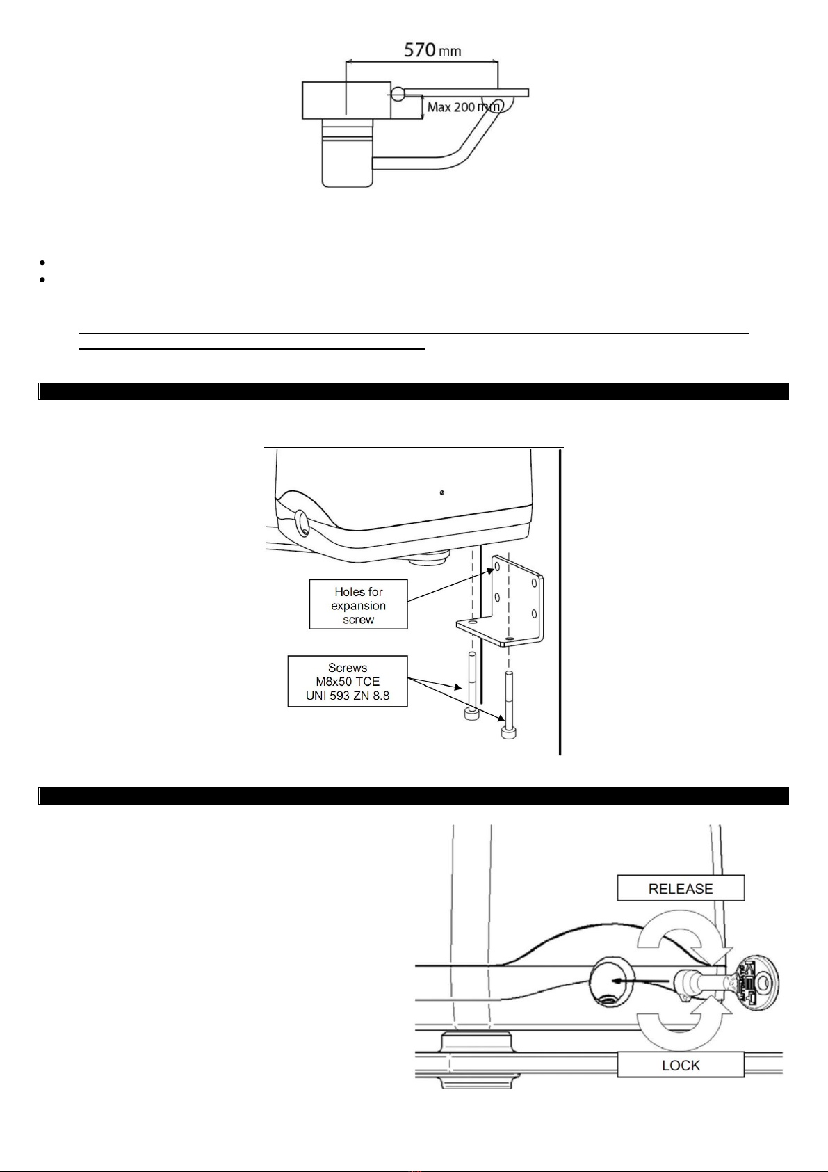
FIXING TO THE GATE AND PRELIMINARY CHECKS

3
Before proceeding with the installation we suggest to go through the followings checks and operations, beside verifying that the structure is comply-
ing to the norms in force.
In particular:
• Check that the wall and/or column are in good conditions, otherwise it will be necessary to reinforce fixing points.
• Keep attention to the run of the leafs, there must be no obstacles which reduce the movement of them.
The door must have no frictions during opening as during closing. If stopped in any position, it has no to move. During movement it must not skid.
WARNING! It is forbidden to put in service the automation, before the machine in which it will be incorporate has been de-
clared complying to dispositions of the directive CEE 22/06/98 .
ASSEMBLING
Open the package and verify that all the elements which compose the automation, are in good status.
UNLOCKING SYSTEM
To release the motor you must follow these operations:
1) Raise the plastic lock on the forehead of the motor.
2) Insert the triangle key;
3) Rotate the key in clockwise till the release;
To lock it rotate anticlockwise till the initial position.

4
MOTOR’S MAINTENANCE
DANGER: for any kind of maintenance, remove always the feeding. The motoreducer is supplied by a permanent grease lu-
brication, therefore it doesn’t need any maintenances. Cables, springs and supports don’t need for periodic maintenance.
In case of failure the system must be not used and professional stuff need to be called.
CONTROL UNIT TABLE
1. Clamps connections feedings and ground CN1
2. Clamps connections motors/ blinking/electric lock
3. Clamps connection output (Commands and Safeties)
4Clamps connection Encoder signals and feedings
5. Signalling led for safety inputs. Led ON = input close
6. Connector for Molex radio
7. Connector for Antenna
8. Button PROG for the programming
9. Dip-switch for setting functions (see referring table)
10. Button step/step P/P
11. Connector batteries charger 900CABAT-30
12. Pin RESET (short-circuit in case of total cancellation of memorized run)
VISIBLE CONTROL ON THE STATE OF THE UNIT
The control unit is designed with the aim to complete the installation in the shortest time possible and therefore to immediately see if the connections
are correct through the switching on of corresponding LEDs:
A. Red Led signal the presence of feeding DL1 POWER, it indicates if the transformer gives out tension (switched-on).
B. Red Led DL4, located in the bottom-right side close to safety input STOP, must be switched-on because it indicates that the contact is closed.
C. Red Led DL3 located in the bottom-right side close to safety input Photocell Open F2 , must be switched-on because it indicates that the contact
is closed. When the ray is interrupted, the led should switch-off.
D. Red Led DL2 located in the bottom-right side close to safety input Photocell Close F1, must be switched-on because it indicates that the contact
is closed. When the ray is interrupted, the led should switch-off.

5
ELECTRICAL CONNECTIONS
To guarantee the safety of operator and to prevent damages to components, while caring out the connections or inserting
the radio receiver, the control unit must be disconnected from electric feeding.
For feeding cables, motors lines, lines for blinker/ courtesy light, electric lock use a cable with appropriate section to the length of the connection
(min 1,5mmq). For auxiliary feedings of commands and the safety contacts, use minimum section of 0.5mmq. In case those cables are too long
(beyond 30m), it’s better to do a decoupling by setting up relays on the control unit.
In case of intervention of a fuse, after removing the problem, change it by another with the same characteristics.
Install safety devices, limit switches, photocells, rubber edges and Stop pushbutton.
If one or more safety devices are not installed, short-circuit the relative clamps with the common of the commands.
All contacts N.C. dress to the same input must be connected in series.
All contacts N.A. dress to the same input must be connected in parallel.
Preview disconnecting devices on the feeding line in an accessible place. For the feeding of the control unit set an appropriate external discon-
necting device (not included with equipment
Hold the cables of feeding separated from those of the encoder with a distance between motor and control unit of maximum 10m. Don’t use
multi pole cables.
Functioning of the Electric lock output, ELS: connect it between clamp N.10 and clamp N.11 –when an opening command is given, 1s of switch-
ing on is executed before the activation of M1
Functioning of flashing light: connect it between clamp N.11 and clamp N.12, maximum power 25W 24Vdc. In opening and in closing, it execute
a forewarn of 1,5s to signal that the automation is starting the movement.
Functioning of “phototest”on the feeding of photocell TX: if you want to execute a phototest cycle on every opening, set Dip 8 = ON and connect
the NEGATIVE feeding of the photocell emitter to clamp N.13
CONNECTION OF MOTORS ELECTRIC FEEDING
Motor M1 : connect between clamp N.6 and clamp N.7
Motor M2 : connect between clamp N.8 and clamp N.9 –Motor M2 in closing, start first.

6
CONNECTION OF MOTORS ENCODER
POSITIVE feeding of encoders are connected to clamp N.20 ENC+.
NEGATIVE feeding of encoders are connected to clamp N.23 ENCIl.
Signal of encoder relative to motor M1 to clamp N. 21 ENC1.
Signal of encoder relative to motor M2 to clamp N. 22 ENC2.
ELECTRONIC CLUTCH
It’s a very important device for emergency, Its calibration stay constant in the time without being subject to usuries like in an usual mechanical
clutch.
A. It is active in closing, but also in opening, when activate invert the sense of the run without disabling the automatic closing, in case it is set-up.
B. If activate two consecutive times, will STOP the gate disconnecting the automatic closing if present: intervening two consecutive times means that
the obstacle is permanent and any movement could be dangerous, forcing then the user to give the opening or closing command.
C. If activate three consecutive times, the control unit will execute an emergency procedure which force the user to do a complete opening manoeu-
vre till the mechanical stop and consequently the closing if the automatic closing is set-up. In this case if working times went lost, the unit would
learn again the normal situation.
INPUTS OF THE CONTROL UNIT AND ITS FUNCTIONING
Functioning Open/Pedestrian PED.
Connect between ClampN.14 and Clamp N.19 Contact N.A. Normally open
It’s a command for opening that, in case we set the functioning with 2 motors, will make motor M1 open completely. If we selected to function with
only one motor, will do a partial opening of the 40% of the run.
Functioning Step /Step P/P
Connect between ClampN.15 and Clamp N.19 Contact N.A. Normally open
It’s a commando for opening that works in two different ways:
Dip 5 = ON an open impulse, during the run it doesn’t accept any commands. It only accept the reopening during closing.
Dip 5 = OFF an open impulse, an impulse Stop, an impulse close.
Functioning photocell Close F1
Connect between Clamp N.16 and Clamp N.19 Contact N.C. Normally closed
This input is considered a safety, the contact can be interrupted in every moment during the closing of the automation provoking the immediate stop
of the motion and then a reverse manoeuvre.
Functioning photocell Open F2
Connect between ClampN.17 and ClampN.19 Contact N.C. Normally closed
This input is considered a safety, the contact can be interrupted in every moment during the opening of the automation provoking the immediate stop
of motion, the automation will continue the opening at the restore of the contact.
Functioning Stop STP
Connect between Clamp N.18 and Clamp N.19 Contact N.C. Normally closed
This input is considered a safety. The contact can be interrupted in every moment stopping immediately the automation and refusing any other func-
tion including the automatic closing.

7
CONNNECTION CLAMPS FEEDINGS CN1
Connection clamps feedings CN1
The CN1 is dedicated to the connection of the control unit feeding:
Clamp 1 VAC and clamp 2 VAC. To connect the 2 cables coming from the transformer where we could measure 22 Vac. Are protected by fuse
F1 10A delayed.
Clamp 3 +24 and clamp 4 –24 are used to connect the feeding of accessories; this output is used for feeding safety devices or accessories
with a fuse F2 of 0,5 A delayed. The maximum power supplied is of 0.5 A.
Clamp N.5 is connect to ground system.
PROGRAMMING THE CONTROL UNIT
Self-learning of mechanical stops in opening and in closing and of the automatic closing time
1.Push the button PROG., the blinker will light fixed to advise the user that it has entered in a programming procedure.
2. Open the leafs in a desired position and push the button P/P; the leaf M2 will go in closing till the mechanical stop, after 2s will start to close the
leaf M1 till the mechanical stop. When both leafs are completely closed, it will open first motor M1 and then motor M2 to reach the mechanical stop
in maximum opening (all the learning procedure of mechanical stops is execute in slowing down). The first manoeuvre that execute the control unit
is a closing one, this is done in order to make the installer understand if the two wires of the motors are connected in the right way. If a closing
doesn’t take place, do a reset of the unit by touching with a screwdriver the 2 pins with the sign RESET. The control unit will stop immediately the
functioning allowing the installer to change the polarity of the cables found incorrectly connected.
3. from the moment in which the leafs have reach the complete opening, it will start the counting of the automatic closing time. At the desired time ,
press again the button P/P, the gate starts a closing manoeuvre that will automatically complete the self-learning procedure.
ATTENTION! Depending on the stop point of maximum opening, automatically in normal operation the control unit
will stop the doors in advance to prevent striking the mechanical stop which MUST be installed.
DIP SWITCH
ATTENTION! Each function variation is confirmed upon completion of closure

8
DISPOSAL
This product is composed of various components which may in turn contain pollutants. Do not dispose in the
environment! Find out about the method for recycling or disposing of the product in compliance with current local laws.
NOTES
PROGET srl
Via Europa, 3 31047 Ponte di Piave (TV) - ITALY
tel.+39 (0)422 / 857377 fax +39 (0)422 / 857367
web: http://www.proget-beb.com email: proget@proget-beb.com
rev. 1.0.3, 04/2009
Table of contents
Other B&R Industrial Equipment manuals
Popular Industrial Equipment manuals by other brands

Mayr
Mayr ROBATIC 500.1 Series Installation and operational instructions

Horizon Fitness
Horizon Fitness PJ-110 instruction manual

ANYKIT
ANYKIT NTS500 user manual

YASKAWA
YASKAWA VARISPEED-656RC5 instruction manual

Siemens
Siemens SITRANS LG Series Firmware update

Branick
Branick 465 Installation, Operation & Repair Parts Information