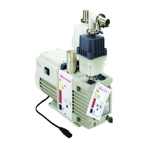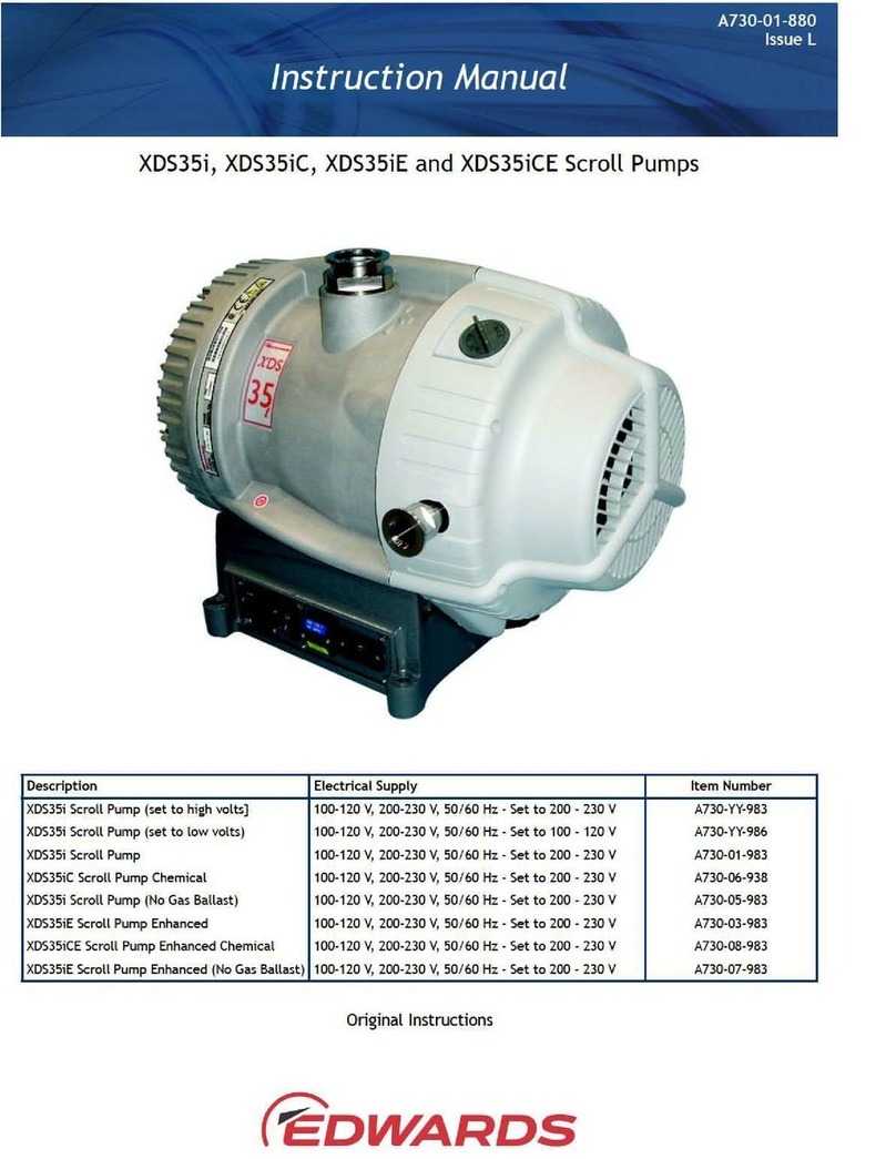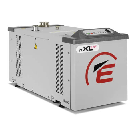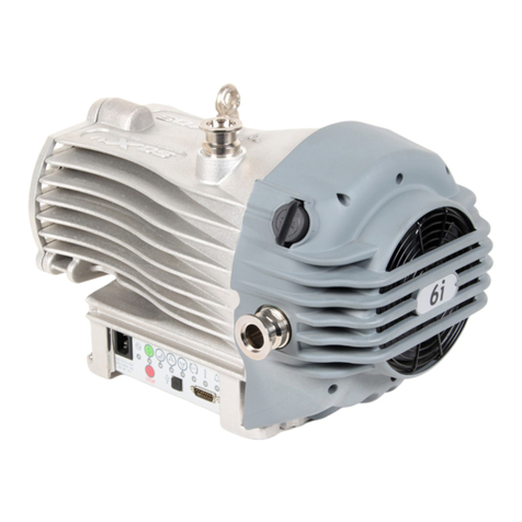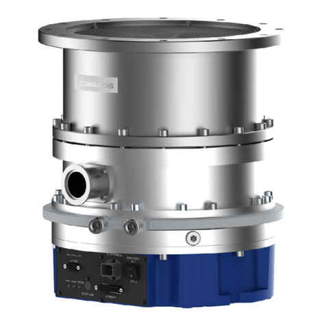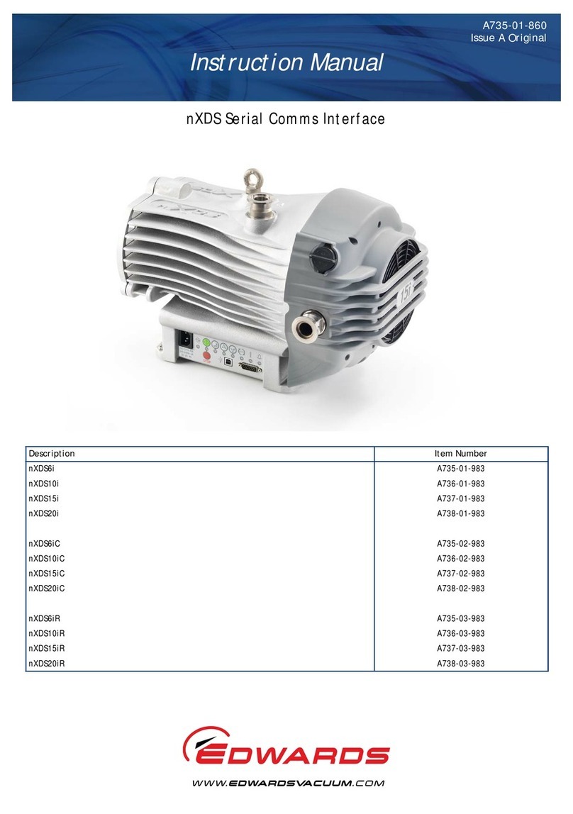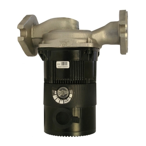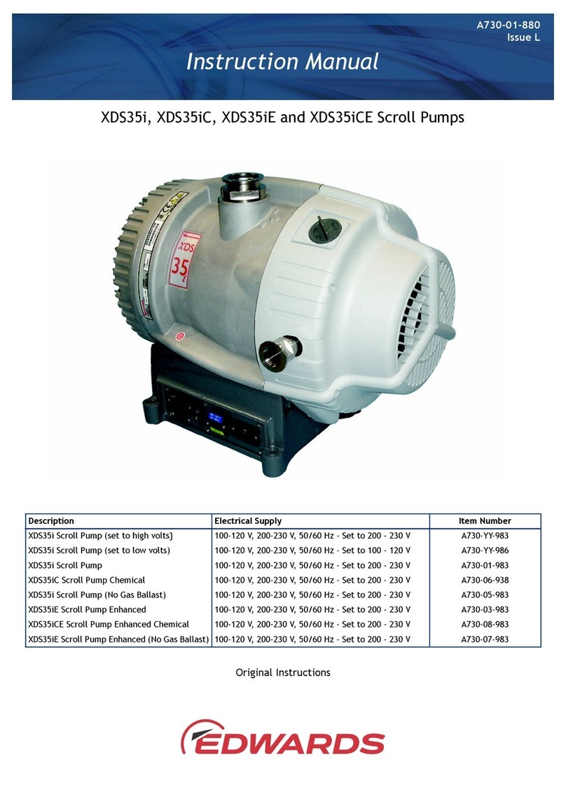
The pump has an NW40 (item 1) inlet and inlet strainer.
The pump mechanism is driven directly by a three‑phase electric motor. The motor is
controlled by a drive, which manages the supply of current to the motor in accordance
with operang condions and allows the pump to be connected to a single phase
supply. The voltage changeover switch beneath the voltage changeover switch cover
(item 8) must be set to the correct posion in accordance with the power supply being
used, refer to Connect the pump to the electrical supply on page 20.
The pump is designed to run from atmospheric pressure however, if the inlet pressure
exceeds 100 mbar for an extended period, the inverter may reduce the motor speed.
The pump will speed up again aer the pressure is reduced. Maximum rated connuous
operang pressure at 40 °C ambient is 40 mbar.
The enhanced pump versions (XDS35iE and 35iCE) are equipped with patented
technology which prevents over‑compression within the scroll mechanism at high
operaonal pressure and large throughput applicaons. Twin by‑pass valves release
suciently compressed gas directly to the pump exhaust, increasing pump eciency,
lowering power consumpon and enhancing pumping speed. Valve operaon occurs at
inlet pressures greater than 300 mbar, meaning the pump is tailored towards
applicaons which dwell at higher pressure. The eliminaon of over‑compression at high
operaonal pressure, reduces power consumpon and diminishes bearing loads,
extending bearing life. Consequently, the enhanced versions are capable of operaon
without limitaons to both the size of vacuum chamber, or the frequency of pump down
on cyclic dues.
Note:
The pump modicaons within the enhanced version have a small adverse eect on the
ulmate vacuum achieved however, the pump has a larger tolerance to operang
altude and ambient temperature.
The pump is air‑cooled by a fan (item 3) mounted at the opposite end to the motor. The
fan will connue to run for one minute aer the pump is switched o. The pump
incorporates a thermal protecon device that will stop the motor in the event of thermal
overload, for example, high ambient temperature. The pump will restart aer cooling
down.
2.4 Gas ballast control
To pump high vapour loads, gas ballast can be delivered into the pump to prevent
condensaon of the vapour carried by the pumped gases.
Air can be introduced to the low vacuum stages through the gas ballast control (item 2)
(not ed on the No Gas Ballast variant). Alternavely, an inert gas such as nitrogen can
be supplied through a suitable external valve and by using the appropriate adaptor,
available as an accessory, refer to Gas ballast adaptor on page 34.
The gas ballast control has three posions:
▪Closed (posion '0')
▪Low ow (posion 'I')
▪High ow (posion 'II')
Page 10
A73001880_M - Introducon


