Graco King E70 User manual

3A8478A
EN
Instructions
E70/E60 King®Electric Driver
Electric driver for application of protective coatings. For professional use only.
Not approved for use in explosive atmospheres or hazardous (classified) locations.
Model 25P291
Important Safety Instructions
Read all warnings and instructions in this
manual and in related manuals before
using the equipment. Save these
instructions.
WLD

2 3A8478A
Contents
Related Manuals . . . . . . . . . . . . . . . . . . . . . . . . . . . 2
Models . . . . . . . . . . . . . . . . . . . . . . . . . . . . . . . . . . . 2
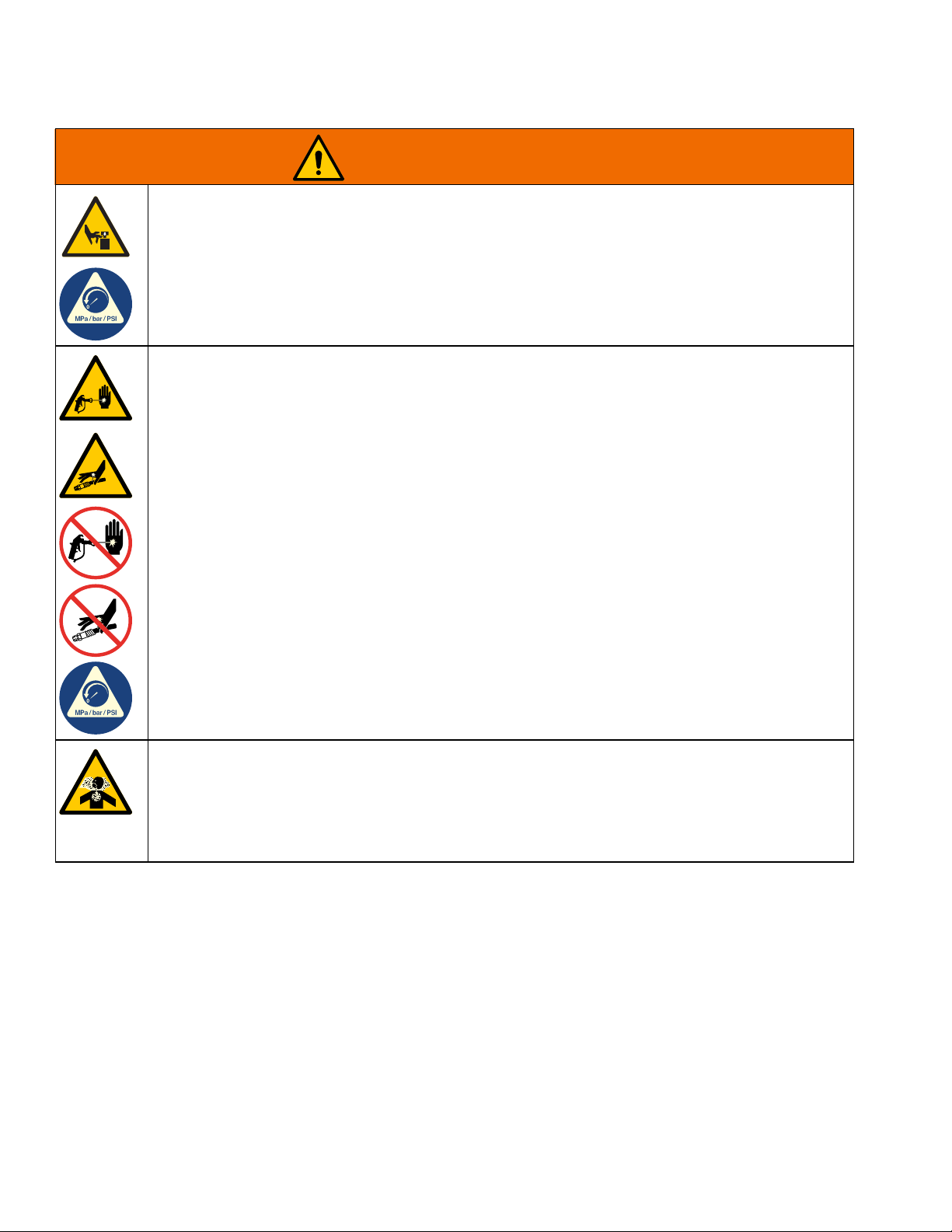
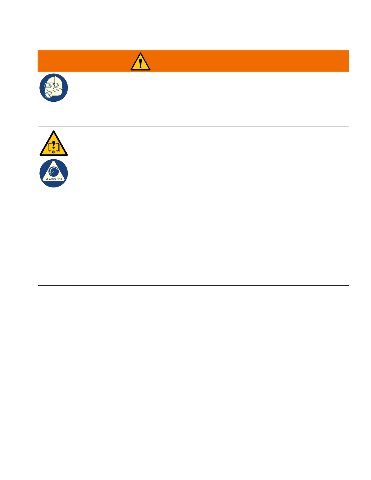
Warnings . . . . . . . . . . . . . . . . . . . . . . . . . . . . . . . . . 3
Component Identification . . . . . . . . . . . . . . . . . . . . 6
Installation . . . . . . . . . . . . . . . . . . . . . . . . . . . . . . . . 7
Power Requirements . . . . . . . . . . . . . . . . . . . . . 7
Connect Power . . . . . . . . . . . . . . . . . . . . . . . . . . 7
Grounding . . . . . . . . . . . . . . . . . . . . . . . . . . . . . . 8
Install Vented Oil Cap Before Using Equipment . 8
Operation . . . . . . . . . . . . . . . . . . . . . . . . . . . . . . . . . 9
Startup . . . . . . . . . . . . . . . . . . . . . . . . . . . . . . . . 9
Shutdown . . . . . . . . . . . . . . . . . . . . . . . . . . . . . . 9
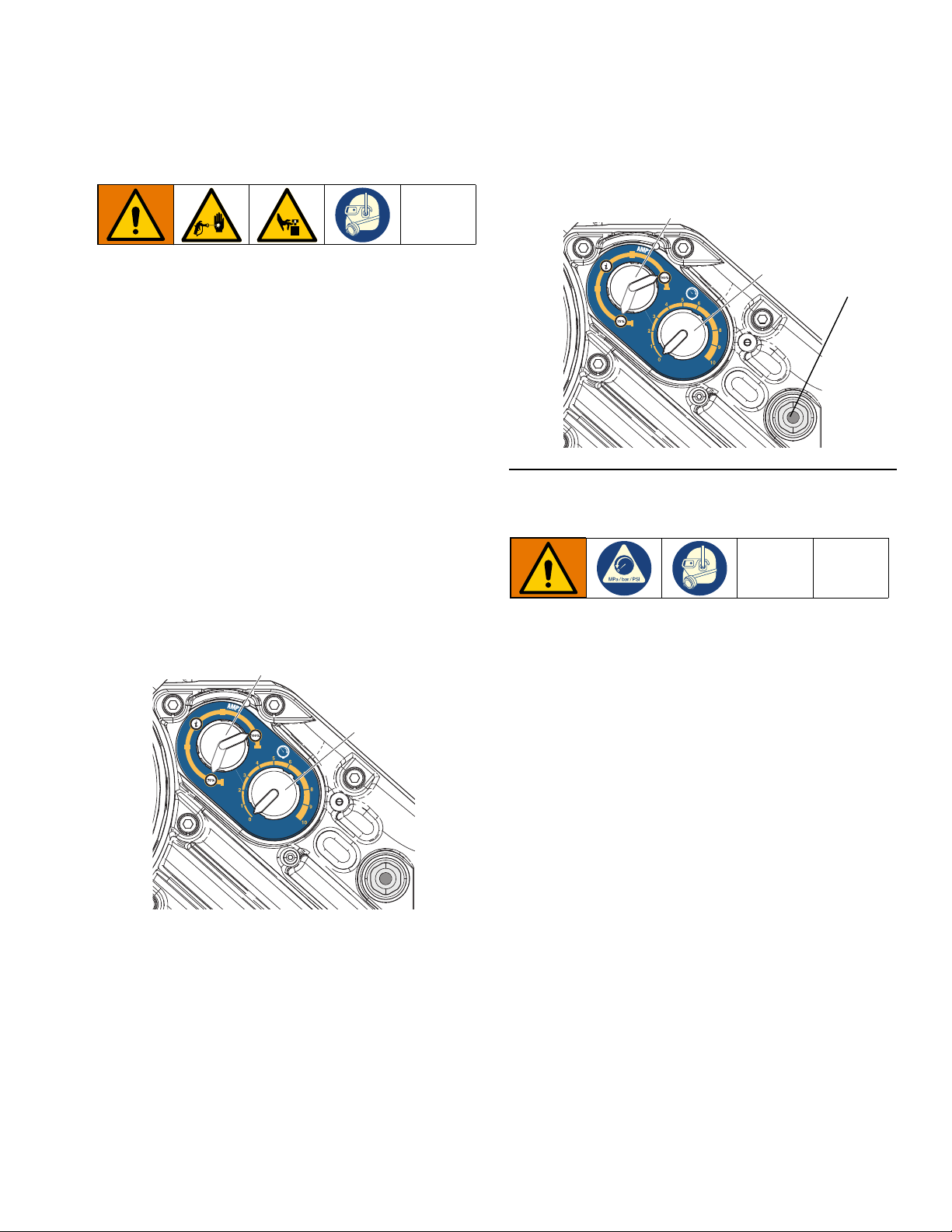
Pressure Relief Procedure . . . . . . . . . . . . . . . . 10
Driver Operation . . . . . . . . . . . . . . . . . . . . . . . . 10
Maintenance . . . . . . . . . . . . . . . . . . . . . . . . . . . . . . 11
Preventative Maintenance Schedule . . . . . . . . 11
Change the Oil . . . . . . . . . . . . . . . . . . . . . . . . . 11
Check Oil Level . . . . . . . . . . . . . . . . . . . . . . . . . 11
Bearing Pre-Load . . . . . . . . . . . . . . . . . . . . . . . 11
Troubleshooting . . . . . . . . . . . . . . . . . . . . . . . . . . 12
Error Code Troubleshooting . . . . . . . . . . . . . . . 12
Standby Mode . . . . . . . . . . . . . . . . . . . . . . . . . . 12
Error Codes Table . . . . . . . . . . . . . . . . . . . . . . . 12
Repair . . . . . . . . . . . . . . . . . . . . . . . . . . . . . . . . . . . 14
Replace Output Seal Cartridge . . . . . . . . . . . . . 14
Replace Fan Fuses . . . . . . . . . . . . . . . . . . . . . . 14
Remove Fan Shroud . . . . . . . . . . . . . . . . . . . . . 15
Disconnect Fan Wires . . . . . . . . . . . . . . . . . . . . 15
Reinstall Fan Wires . . . . . . . . . . . . . . . . . . . . . . 16
Replace Electronics Cover . . . . . . . . . . . . . . . . 16
Replace Stroke Position Sensor . . . . . . . . . . . . 19
Replace Encoder . . . . . . . . . . . . . . . . . . . . . . . . 20
Repair Token Cable . . . . . . . . . . . . . . . . . . . . . . 22
Software Update Procedure . . . . . . . . . . . . . . . 23
Parts . . . . . . . . . . . . . . . . . . . . . . . . . . . . . . . . . . . . 24
Electric Driver . . . . . . . . . . . . . . . . . . . . . . . . . . 24
Parts List - Electric Driver (25P291) . . . . . . . . . 25
Mounting Hole Pattern . . . . . . . . . . . . . . . . . . . . 26
Wiring Diagrams . . . . . . . . . . . . . . . . . . . . . . . . . . 27
Dimensions . . . . . . . . . . . . . . . . . . . . . . . . . . . . . . . 28
Technical Specifications . . . . . . . . . . . . . . . . . . . . 29
California Proposition 65 . . . . . . . . . . . . . . . . . . . 29
Recycling and Disposal . . . . . . . . . . . . . . . . . . . . . 29
End of Product Life . . . . . . . . . . . . . . . . . . . . . . 29
Graco Extended Warranty . . . . . . . . . . . . . . . . . . . 30
Related Manuals
Manuals are available at www.graco.com.
Models
Manual in
English
Description
3A8477 E70/E60 King Sprayer Manual
Part Series Description
25P291 B King Driver, Non-Haz Loc

Warnings
3A8478A 3
Warnings
The following warnings are for the setup, use, grounding, maintenance, and repair of this equipment. The
exclamation point symbol alerts you to a general warning and the hazard symbols refer to procedure-specific risks.
When these symbols appear in the body of this manual or on warning labels, refer back to these Warnings.
Product-specific hazard symbols and warnings not covered in this section may appear throughout the body of this
manual where applicable.
WARNING
ELECTRIC SHOCK HAZARD
This equipment must be grounded. Improper grounding, setup, or usage of the system can cause
electric shock.
• Turn off and disconnect power cord before servicing equipment.
• Connect only to grounded electrical outlets.
• Use only 3-wire extension cords.
• Ensure ground prongs are intact on power and extension cords.
• Do not expose to rain. Store indoors.
• Wait five minutes after disconnecting power cord before servicing.
FIRE AND EXPLOSION HAZARD
Flammable fumes, such as solvent and paint fumes, in work area can ignite or explode. Paint or
solvent flowing through the equipment can cause static sparking. To help prevent fire and explosion:
• Use equipment only in well-ventilated area.
• Eliminate all ignition sources, such as pilot lights, cigarettes, portable electric lamps, and plastic
drop cloths (potential static sparking).
• Ground all equipment in the work area. See Grounding instructions.
• Never spray or flush solvent at high pressure.
• Keep work area free of debris, including solvent, rags and gasoline.
• Do not plug or unplug power cords, or turn power or light switches on or off when flammable fumes
are present.
• Use only grounded hoses.
• Hold gun firmly to side of grounded pail when triggering into pail. Do not use pail liners unless they
are anti-static or conductive.
•Stop operation immediately if static sparking occurs or you feel a shock.Do not use equipment
until you identify and correct the problem.
• Keep a working fire extinguisher in the work area.
BURN HAZARD
Equipment surfaces and fluid that is heated can become very hot during operation. To avoid severe
burns:
• Do not touch hot fluid or equipment.

Warnings
4 3A8478A
MOVING PARTS HAZARD
Moving parts can pinch, cut or amputate fingers and other body parts.
• Keep clear of moving parts.
• Do not operate equipment with protective guards or covers removed.
• Equipment can start without warning. Before checking, moving, or servicing equipment, follow the
Pressure Relief Procedure and disconnect all power sources.
SKIN INJECTION HAZARD
High-pressure fluid from gun, hose leaks, or ruptured components will pierce skin. This may look like
just a cut, but it is a serious injury that can result in amputation. Get immediate surgical treatment.
• Do not spray without tip guard and trigger guard installed.
• Engage trigger lock when not spraying.
• Do not point gun at anyone or at any part of the body.
• Do not put your hand over the spray tip.
• Do not stop or deflect leaks with your hand, body, glove, or rag.
• Follow the Pressure Relief Procedure when you stop spraying and before cleaning, checking, or
servicing equipment.
• Tighten all fluid connections before operating the equipment.
• Check hoses and couplings daily. Replace worn or damaged parts immediately.
TOXIC FLUID OR FUMES HAZARD
Toxic fluids or fumes can cause serious injury or death if splashed in the eyes or on skin, inhaled, or
swallowed.
• Read Safety Data Sheets (SDSs) to know the specific hazards of the fluids you are using.
• Store hazardous fluid in approved containers, and dispose of it according to applicable guidelines.
WARNING

Warnings
3A8478A 5
PERSONAL PROTECTIVE EQUIPMENT
Wear appropriate protective equipment when in the work area to help prevent serious injury, including
eye injury, hearing loss, inhalation of toxic fumes, and burns. Protective equipment includes but is not
limited to:
• Protective eyewear, and hearing protection.
• Respirators, protective clothing, and gloves as recommended by the fluid and solvent manufacturer.
EQUIPMENT MISUSE HAZARD
Misuse can cause death or serious injury.
• Do not operate the unit when fatigued or under the influence of drugs or alcohol.
• Do not exceed the maximum working pressure or temperature rating of the lowest rated system
component. See Technical Specifications in all equipment manuals.
• Use fluids and solvents that are compatible with equipment wetted parts. See Technical
Specifications in all equipment manuals. Read fluid and solvent manufacturer’s warnings. For
complete information about your material, request Safety Data Sheets (SDSs) from distributor or
retailer.
• Do not leave the work area while equipment is energized or under pressure.
• Turn off all equipment and follow the Pressure Relief Procedure when equipment is not in use.
• Check equipment daily. Repair or replace worn or damaged parts immediately with genuine
manufacturer’s replacement parts only.
• Do not alter or modify equipment. Alterations or modifications may void agency approvals and
create safety hazards.
• Make sure all equipment is rated and approved for the environment in which you are using it.
• Use equipment only for its intended purpose. Call your distributor for information.
• Route hoses and cables away from traffic areas, sharp edges, moving parts, and hot surfaces.
• Do not kink or over bend hoses or use hoses to pull equipment.
• Keep children and animals away from work area.
• Comply with all applicable safety regulations.
WARNING

Component Identification
6 3A8478A
Component Identification
* The driver is pre-filled with oil from the factory. The temporary unvented cap is for shipping purposes only and must
be replaced with the supplied vented cap before use.
<
;
0
$
3&1
/
6*+
.
WLD
; =
==
==
Ref. Description
A Driver
C Lift Ring
G Oil Drain Plug
H Driver Output Shaft
K Oil Sight Glass
L Status Indicator Light (LED)
M Mode Selector Knob
N Pressure Control Knob
*P Oil Fill Cap (vented)
S Power Switch (Lock-out tag-out equipped)
Y Electrical Junction Box
Z Electrical Junction Box Cover
ZZ Ground Screws
X1 Cord Grip (for Power Cord)
X2 Cord Grip (for Fan Cable)
Ref. Description

Installation
3A8478A 7
Installation
Power Requirements
See Table 1 for power source requirements. The
system requires a dedicated circuit protected with a
circuit breaker.
Connect Power
1. Cut power cord wires to the following lengths:
- Ground wire - 6.5 inches (16.5 cm)
- Power wires - 3.0 inches (7.6 cm)
- Add ferrules as necessary. See FIG. 1.
2. Bring cord to unit and remove four screws to
separate junction box cover (Z) with power switch
(S) from junction box (Y). See FIG. 1.
3. With junction box cover (Z) and power switch (S)
detached from machine, wires inside junction will
appear as below.
NOTE: The two fan harness wires will be installed in
disconnect block (J) in both 1L1 and 3L2 terminals.
4. Insert power cord (from step 1) through cord grip
(X1) and into junction box (Y). Attach the power
cord ground wire to the lower ground terminal inside
junction box (Y).
5. Power wires should be installed into 2T1 and 4T2
terminals. See Wiring Diagrams on page 27.
NOTE: The upper ground screw is used by the fan wire
harness and should not be used for both connections.
6. Place fan wires and other power wires into open
area on either side of disconnect block (J) as space
permits. Reinstall junction box cover (Z).
Improper wiring may cause electric shock or other
serious injury. All electrical wiring must be done by a
qualified electrician and comply with all local codes
and regulations.
Table 1: Power Source Specifications
Voltage Phase Hz Current
200-240 VAC 1 50/60 20 A
100-120 VAC 1 50/60 30 A
FIG. 1: Power Cord
GROUND
POWER
FIG. 2: Grounding Wire
FIG. 3: Junction Box Connections
NOTICE
If wires get pinched when the screws are tightened,
damage will occur. Make sure all wires are routed
correctly before installation.
WLD
J
S
Z
WLD
ground
wire
X1

Installation
8 3A8478A
7. Replace junction box screws and washers removed
in step 2 and tighten cord grip (X1) to securely hold
power cord in junction box (Y). See FIG. 4.
Grounding
Driver: The driver is grounded through the power cord.
See Connect Power, page 7.
Install Vented Oil Cap Before
Using Equipment
The driver gear-box is pre-filled with oil. The temporary
unvented cap (PX) prevents oil leaks during shipment.
This temporary cap must be replaced with the vented oil
cap (P), supplied with the equipment, before use.
FIG. 4: Junction Box Screws and Strain Relief Cord
Grip
WLD
X1
The equipment must be grounded to reduce the risk
of static sparking and electric shock. Electric or static
sparking can cause fumes to ignite or explode.
Improper grounding can cause electric shock.
Grounding provides an escape wire for the electric
current.
FIG. 5: Unvented and Vented Oil Caps
PX
P
ti39781a

Operation
3A8478A 9
Operation
Startup
1. Perform Installation procedures starting on page 7.
2. Turn the pressure control knob (N) fully
counterclockwise to 0.
3. Connect the power cord to a power source.
4. Pull mode selector knob (M) out and set it to the
desired mode:
- 100% Power (High Amp) Mode*
- 75% Power (Low Amp) Mode**
Push in the knob to lock.
* See Technical Specifications, page 29, for input
power information.
** Reduces current draw to:
- 15A for 200-240 V operation, or
- 20A for 100-120 V operation
5. Turn the power switch (S) ON.
6. Check that the status indicator (L) is on and not
flashing.
Shutdown
To shut down the system, perform the Pressure Relief
Procedure on page 10.
WLD
1
0
FIG. 6: Status Indicator Light
WLD
1
0
L

Operation
10 3A8478A
Pressure Relief Procedure
1. Pull pressure control knob (N) out and turn
counterclockwise until it stops. Push the knob in to
lock.
2. Turn power switch (S) OFF.
3. Disconnect the power cord from the power source.
4. Relieve all fluid pressure as explained in your
separate system manual. See Related Manuals,
page 2.
Driver Operation
Pressure Control
The driver will adjust the speed to maintain a constant
fluid pressure.
1. Pull the pressure control knob (N) out to set.
2. Turn the knob clockwise to increase the pressure, or
counter-clockwise to decrease the pressure. Push
the knob to lock.
Follow the Pressure Relief Procedure
whenever you see this symbol.
This equipment stays pressurized until pressure is
manually relieved. To help prevent serious injury from
pressurized fluid, such as skin injection and moving
parts, follow the Pressure Relief Procedure when you
stop spraying and before cleaning, checking, or
servicing the equipment.

Maintenance
3A8478A 11
Maintenance
Preventative Maintenance
Schedule
The operating conditions of your particular system
determine how often maintenance is required. Establish
a preventative maintenance schedule by recording
when and what kind of maintenance is needed, and
then determine a regular schedule for checking your
system.
Change the Oil
NOTE: Change the oil after a break-in period of 200,000
to 300,000 cycles. After the break-in period, change the
oil once per year.
1. Place a minimum 2 quart (1.9 liter) container under
the oil drain port. Remove the oil drain plug (G).
Allow all oil to drain from the driver.
2. Reinstall the oil drain plug (G). Torque to 18-23 ft-lb
(25-30 N•m).
3. Open the oil fill cap (P) and add Graco Part 16W645
ISO 220 silicone-free synthetic EP gear oil. Check
the oil level in the sight glass (K). (See FIG. 8.) Fill
until the oil level is near the halfway point of the
sight glass. The oil capacity is approximately 1.0 -
1.2 quarts (0.9 - 1.1 liters). Do not overfill.
4. Reinstall the oil fill cap (P).
Check Oil Level
Check the oil level in sight glass (K). (See FIG. 8.) The
oil level should be near the halfway point of the sight
glass when the driver is not running. If oil is low, open oil
fill cap (P) and add Graco Part No. 16W645 ISO 220
silicone-free synthetic EP gear oil. See FIG. 8.
The oil capacity is approximately 1.0 - 1.2 quarts (0.9 -
1.1 liters). Do not overfill.
Bearing Pre-Load
See FIG. 8. The bearing pre-loads (R) are factory set
and are not user adjustable. Do not adjust the bearing
pre-loads.
NOTICE
Do not open/remove gear cover. The gear side is not
intended to be serviced. Opening the gear cover may
alter the factory set bearing pre-load and may reduce
the product life.
FIG. 7: Oil Drain Plug
NOTICE
Do not over-torque. The drain plug can become
stripped and damaged.
WLD
*
NOTICE
Only use oil with Graco part number 16W645. Any
other oil may not lubricate properly and can cause
damage to the drive train.
FIG. 8: Sight Glass and Oil Fill Cap
WLE
P
K
R

Troubleshooting
12 3A8478A
Troubleshooting
Error Code Troubleshooting
Error codes can take two forms:
• Alarm: Alerts you to the cause of the alarm and
shuts down the driver.
• Deviation: Alerts you to the problem, but the driver
may continue to run past the set limits until the
system absolute limits are reached.
NOTE: The blink code is displayed using the status
indicator (L) on the driver. The blink code given below
indicates the sequence. For example, blink code 2
indicates two blinks, a pause, and then repeats.
NOTE: To clear an error code, cycle power by turning
the power switch (S) to the OFF position for at least 30
seconds before turning back ON.
Standby Mode
When slow blinking is displayed, the driver has entered
Standby Mode. When the driver is on and pressurized
but the pump has not moved any material, the driver will
enter Standby Mode.
Standby Mode will be exited when:
• Material starts to dispense and causes the pump to
move, OR
• The pressure control knob (N) is adjusted, OR
• The power switch (S) is cycled OFF and ON
Error Codes Table
Blink Code Error Type Troubleshooting Steps
1 Alarm Pump Diving
The pump is diving rapidly. A pressure imbalance between the up and down stroke
of the pump is causing the pump to dive with excessive speed.
• Pump diving may occur when the pump runs out material while spraying at high
pressure.
• Verify that material is being properly fed to the pump.
• Pressure from the hose could flow back into the pump on the down stroke.
• Verify that the check valve is installed and is properly working.
2 Alarm Voltage Too Low
• Verify that line voltage is within the range specified in Technical Specifications,
page 29.
• Cycle power and check status indicator (L) to see if the error is still active.
3 Alarm Voltage Too High
• Verify that line voltage is within the range specified in Technical Specifications,
page 29.
• Cycle power and check status indicator (L) to see if the error is still active.

Troubleshooting
3A8478A 13
4 Deviation High Temperature
The temperature of the system is near the maximum operation temperature. The
performance has been reduced to prevent the driver from completely shutting down.
• Check fan operation. Clean the fan and driver housing.
• Reduce pressure, duty cycle, or gun tip size.
• Move the unit to a cooler location.
5 Deviation Low Temperature
• Warm equipment.
• Circuit board cannot read motor temperature sensor. Check if the sensor is
plugged into the correct connector.
6 Alarm Motor Temperature Fault
Motor is running too hot. Allow unit to cool.
• Check fan operation. Clean overspray buildup from the fan and driver housing.
• Reduce pressure, duty cycle, or gun tip size.
• Move the unit to a cooler location.
7 Alarm Board Temperature Fault
The control board is running too hot. Allow the unit to cool.
• Check fan operation. Clean overspray buildup from the fan and driver housing.
• Reduce pressure, duty cycle, or gun tip size.
• Move the unit to a cooler location.
8 Alarm Encoder Calibration Error
• Cycle power and check status indicator (L) to see if the error is still active.
• Calibrate the encoder (this code will blink if calibration is in progress).
9 Alarm Encoder Error
• Cycle power and check the status indicator (L) to see if the error is still active.
• Verify that the encoder cable (D) is connected securely (see Wiring Diagrams,
page 27).
• The encoder may need replacement.
10 Alarm Software Versions Do Not Match
• See your system manual, Related Manuals, page 2. for software token part
number.
• Obtain software update token and follow Software Update Procedure, page 23.
11 Alarm Circuit Board Communication Failure
Cycle power and check status indicator (L) to see if the error is still active.
12 Alarm Internal Circuit Board Hardware Failure
Cycle power and check status indicator (L) to see if the error is still active.
13, 14 Alarm Internal Software Error
Cycle power and check status indicator (L) to see if the error is still active.
Slow Blink Deviation See Standby Mode, page 12.
Blink Code Error Type Troubleshooting Steps

Repair
14 3A8478A
Repair
Replace Output Seal Cartridge
1. Stop pump at the top of its stroke. Shut off and
disconnect power to driver.
2. Follow the Pressure Relief Procedure on page 10.
3. Disconnect the lower from the driver. See your
system manual, Related Manuals, page 2.
4. Drain oil from driver. See Change the Oil, page 11.
5. Reinstall oil drain plug (25). Torque to 18-23 ft-lb
(25-30 N•m).
6. Unscrew seal cartridge assembly (19) from driver.
See Parts, page 24.
7. Install new seal cartridge assembly (19). Torque to
175-200 ft-lb (240-280 N•m).
8. Fill with oil. See Change the Oil, page 11.
9. Reconnect lower to driver (see your system manual,
See Related Manuals, page 2).
Replace Fan Fuses
1. Follow the Pressure Relief Procedure on page 10.
2. Disconnect unit from power source.
3. Remove four screws (91) and remove junction box
cover (89) from driver to gain access to the
disconnect block (7). Gently pull out fuse holders.
4. Unscrew fuse holder, remove old fuse, and replace
with new fuse (Graco part number 116682) (5 mm x
20 mm, 500 mA, 250V, Slow Blow). Reconnect fuse
holder and tighten.
5. Repeat step 4 with second fuse.
6. Tuck wires back into junction box (88) and reinstall
junction box cover (89) with four screws (91) and
washers (43).
NOTICE
Do not over-torque. The drain plug can become
stripped and damaged.
FIG. 9: Fuse Location
NOTICE
If wires get pinched when the screws are tightened,
damage will occur. Make sure all wires are routed
correctly before installation.
WLD
7
88
89
91
43

Repair
3A8478A 15
Remove Fan Shroud
1. Disconnect the unit from the power source.
2. Remove screws (56, 24) that attach the fan
assembly to driver and pull up on end farthest from
junction box. Slide assembly toward the junction
box to remove.
3. Attach the fan assembly
a. To reattach the fan assembly, slide cover into
slots for tabs located on the junction box side of
the driver and gently push down far end (see
FIG. 10).
b. To install a new fan assembly, follow
Disconnect Fan Wires.
Disconnect Fan Wires
1. Follow the Pressure Relief Procedure on page 10.
2. Disconnect unit from power source.
3. Remove four screws (91) and remove junction box
cover (89) from driver to gain access to the
disconnect block (7). See FIG. 9.
4. Loosen terminal screws for 1L1 and 3L2 and gently
remove wires from each location.
5. Use a wire cutter to cut ferrule tips from fan wires
and motor power wires close to ferrules.
NOTE: Do not cut the tip off of the ground wire.
See FIG. 11.
6. Remove the upper grounding screw (201) and
disconnect green fan ground wire.
7. Loosen fan wire harness cord grip (82) attached to
driver and pull out fan wire harness.
FIG. 10: Fan Assembly Removal
24
92
56 43
FIG. 11: Remove Wires
FIG. 12: Fan Grounding Screw
FIG. 13: Remove Fan Wires
WLD
/
/
/
7
7
7
WLD
201
WLD
82

Repair
16 3A8478A
Reinstall Fan Wires
1. Route wires through fan cord grip (82) attached to
driver (see FIG. 13 on page 15).
2. Reattach the ground wire to the upper grounding
screw. Tighten ground screw. See FIG. 2 on page 7.
3. Use a ferrule to connect each fan wire to one of two
wires coming out of the electronics cover (3) and
crimp ferrule with a crimp tool. Then attach one wire
set into the disconnect block (7) terminals 1L1 and
the other wire into location 3L2. See FIG. 14 on
page 16.
4. Tuck wires back into junction box (88) and reinstall
junction box cover (89) with four screws (91).
5. Tighten fan cord grip (82) (see FIG. 13 on page 15).
Replace Electronics Cover
Removal
1. Follow the Pressure Relief Procedure on page 10.
2. Disconnect unit from power source.
3. Remove the lower from the driver (see your system
manual, Related Manuals, page 2).
NOTE: This is required to complete the calibration
procedure (page 17).
4. Follow Remove Fan Shroud and Disconnect Fan
Wires on page 15.
5. Remove lower ground screw and power cord
ground wire, then remove the box sleeve mounting
screw (126) and box sleeve (88).
6. Remove 12 screws (24) and washers (43) from
electronics cover (3).
FIG. 14: Attach Grounding Screw
NOTICE
If wires get pinched when the screws are tightened,
damage will occur. Make sure all wires are routed
correctly before installation.
WLD
/
/
/
7
7
7
FIG. 15: Junction Box Sleeve
FIG. 16: Electronics Cover Removal
WLD
126
88
43
WLD
3
24
43

Repair
3A8478A 17
7. Carefully separate the electronics cover (3) from the
driver, then disconnect the wires.
8. Pull wire connectors down, out of the harness clip
and disconnect the motor power and motor
temperature wires.
9. Disconnect the stroke position sensor (29).
10. Disconnect encoder cable (D).
11. Disconnect the token cable (86).
FIG. 17: Remove Electronics Cover
NOTICE
All wires must be disconnected before the cover is
completely removed. Hold the cover in place while
disconnecting wires or let the cover rest on a work
surface to avoid damaging the wires and connections.
FIG. 18: Motor Wires
WLD
3
WL[[[[D
WLD
FIG. 19: Stroke Position Sensor
FIG. 20: Encoder Cable
FIG. 21: Token Cable
WLD
29
WLD
E
D
WLD
86

Repair
18 3A8478A
Installation
1. Reconnect all wires:
• Motor power and motor temperature sensor. See
FIG. 18 on page 17.
• Token cable (86). See FIG. 21 on page 17.
• Encoder cable (D). See FIG. 20 on page 17.
• Stroke position sensor (29). See FIG. 19 on page
17.
2. Install electronics cover (3), 12 washers (43), 12
screws (24) and torque to 15-20 ft-lb (20-27 N•m).
See FIG. 16, page 16.
3. Follow Reinstall Fan Wires on page 16.
4. Follow Connect Power on page 7.
5. Connect power cord to power source.
Calibration
NOTE: The lower must be removed from the driver in
order to calibrate the driver correctly. The calibration
stroke length is longer than the operating stroke.
Leaving the lower attached will cause the driver rod to
contact the lower rod and it will not calibrate correctly.
1. Cycle power to the driver by first turning the power
switch (S) to OFF, and then to ON again.
2. Wait for the status indicator LED (L) to turn on solid
or start blinking.
3. Within 30 seconds, rapidly turn the pressure control
knob (N) back and forth from 0 to 10 at least five
times and then set the knob back to 0. If the status
indicator LED (L) was solid before, it will begin
blinking an encoder calibration error (code 8) during
the calibration process.
- The driver output shaft (H) will move up and
down slowly over the course of several minutes.
- Midway through the auto-calibration process,
the driver output shaft (H) will pause as it moves
to the next step.
- The driver output shaft (H) will move up and
down faster 5-6 times.
4. Ensure the auto-calibration process is complete
before continuing. Wait for the LED to stop blinking.
Reattach Pump Lower
See your system manual, Related Manuals, page 2
NOTICE
If wires get pinched when the cover screws are
tightened, damage will occur. Make sure all wires are
positioned inside the cover before installation.

Repair
3A8478A 19
Replace Stroke Position Sensor
Overview
The stroke position sensor is used to determine where
the driver output shaft (H) is in the stroke.
Tools Required
• 6 mm Hex Wrenches
• 13 mm Open-Ended Wrench
• 6 mm Open-Ended Wrench
• Phillips Screwdriver (#2)
• Torque Wrench (15 ft-lb, 20 N•m)
Prepare Driver
1. Follow Pressure Relief Procedure, page 10.
2. Disconnect the unit from the power source.
3. Remove the pump lower from the driver per your
system manual. See Related Manuals, page 2.
Remove Electronics Cover
NOTE: Refer to FIG. 16, page 16.
1. Remove the 12 screws (24) and washers (43) that
hold on the electronics cover (3) using a 6 mm hex
wrench. Place bolts in a safe location.
2. Pull the cover straight off of the alignment pins that
hold the cover in place.
3. Support the cover after it has been removed to
prevent putting excess strain on the wires inside.
Remove Stroke Position Sensor
1. Unplug the stroke position sensor (29) from the
control board (see Wiring Diagrams, page 27).
2. Loosen the stroke position sensor jam nut using a
13 mm wrench.
3. Unscrew the stroke position sensor (29) from the
center housing using a 6 mm open ended wrench.
NOTE: Allow wires to rotate with position sensor to
prevent twisting.
Install New Stroke Position Sensor
1. Carefully screw the replacement stroke position
sensor into the center housing.
2. Use the 6 mm wrench to complete the installation of
the stroke position sensor. Be careful not to use
excessive torque. Stop once the position sensor
bottoms out in the bore.
3. Tighten the jam nut on the stroke position sensor
finger tight.
4. Plug the stroke position sensor into the control
board (see Wiring Diagrams, page 27).
NOTICE
To avoid damage to the electronic components, wear
grounding strap (Graco part 112190 - not supplied)
and ground appropriately.
NOTICE
To avoid equipment damage, carefully support the
cover when removing the last bolt. Hold the cover
horizontally and take care that the wires are not pulled
tight.
FIG. 22: Remove Stroke Position Sensor
NOTICE
Do not overtighten the stroke position sensor. Damage
to the position sensor may result.
NOTICE
Do not use a wrench to tighten the jam nut. Damage to
the position sensor may result.
WLD
29

Repair
20 3A8478A
Reinstall Electronics Cover onto Driver
1. Plug in all connectors. Ensure all connectors are
securely attached to the control board. See Wiring
Diagrams, page 27.
2. Secure loose motor wires into the clip inside the
housing (see Wiring Diagrams, page 27).
3. Reinstall electronics cover (3) onto the center
housing.
4. Install the 12 screws (24) and washers (43) using a
6 mm hex wrench. See FIG. 16, page 16.
NOTE: Ensure the lock washers are still in place.
5. Torque the screws to 15 ft-lb (20 N•m).
Reattach Pump Lower
See your system manual, Related Manuals, page 2.
Replace Encoder
Overview
The encounter is used by the driver for two purposes.
First, the encoder tells the control board where the
motor is in its mechanical rotation and uses that
information to properly control the motor torque.
Second, it controls stroke length by allowing the control
board to count the number of complete motor rotations.
Tools Required
• 6 mm Hex Wrench
• 0.050 in Hex Wrench
• Phillips Screwdriver (#1)
• Torque Wrench (15 ft-lb, 20N•m)
• Blue (Medium) Thread Locking Compound
1. Follow the Pressure Relief Procedure, page 10.
2. Disconnect the unit from the power source.
3. Remove screws (56, 24) that attach the fan
assembly to the driver and pull up on the end
farthest from the junction box. Slide the assembly
toward the junction box to remove.
4. Use a 6 mm hex wrench to remove the last bolt (24)
and washer (43) from the motor cover.
Make sure wires are not pinched when re-installing
covers. Wires will be damaged and create an
electrical hazard and/or fire and explosion hazard if
pinched.
FIG. 23: Remove Fan
FIG. 24: Remove Motor Cover
24
92
56 43
24
43
This manual suits for next models
2
Table of contents
Other Graco DC Drive manuals
Popular DC Drive manuals by other brands

Boston gear
Boston gear BETAplus Matrix Installation and operation

Becker
Becker P5-20...L120-11 Series Assembly and operating instructions

KEBCO
KEBCO COMBIVERT S4 instruction manual

Oriental motor
Oriental motor CVD Series operating manual

B+K precision
B+K precision 8500 user manual

Oriental motor
Oriental motor BLE Series operating manual