manuals.online logo
Brands
  1. Home
  2. •
  3. Brands
  4. •
  5. Graco
  6. •
  7. Industrial Equipment
  8. •
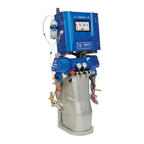
  9. Graco Reactor E-30i Use and care manual

Graco Reactor E-30i Use and care manual

Repair-Parts
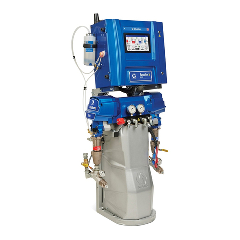
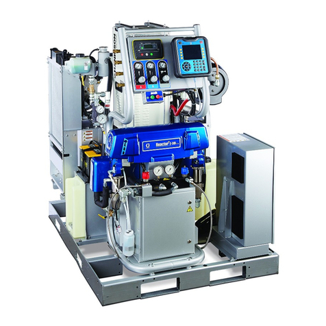
Reactor® E-30i and E-XP2i
3A1706K
EN
Electric, Heated, Integrated Plural Component Proportioning System With Integrated Generator. For
spraying polyurethane foam and polyurea coatings. For professional use only. Not for use in explosi e
atmospheres or hazardous locations.
Important Safety Instructions
Read all warnings and instructions in this manual.
Save these
instructions.
PROVEN QUALITY. LEADING TECHNOLOGY.
Contents
Warnings .............................................................3
Important Two-Component Material
Information .............................................7
Proportioner Models .............................................9
S stems............................................................. 11
Accessories........................................................ 12
Supplied Manuals............................................... 13
Related Manuals ................................................ 13
Troubleshooting.................................................. 14
Error Codes and Troubleshooting.................. 14
Load Center Diagnostics .............................. 37
Repair................................................................ 46
Before Beginning Repair............................... 46
Pressure Relief Procedure............................ 46
Flushing ...................................................... 47
Flush Inlet Strainer Screen ........................... 48
Shutdown.................................................... 49
Drain Coolant .............................................. 50
Refill Proportioner Coolant Loop ................... 51
Refill Engine Coolant Loop ........................... 52
Coolant Specifications.................................. 53
Change Pump Lubricant............................... 53
Remove Pump............................................. 54
Install Pump ................................................ 56
Repair Drive Housing ................................... 56
Repair Motor Brushes .................................. 59
Repair Electric Motor.................................... 61
Repair Circuit Breaker Module ...................... 62
Replace Rela s and Fuses........................... 64
Replace Transducers ................................... 65
Replace Fans .............................................. 66
Repair Booster Heater.................................. 68
Repair Heated Hose..................................... 71
Repair Fluid Temperature Sensor
(FTS)............................................. 72
Replace Heat Exchangers ............................ 74
Replace Power Suppl ................................. 77
Replace Circulation Pump ............................ 78
Repair Sight Glass Filter............................... 79
Repair Filter Housing Filter ........................... 80
Remove Fuel Tank....................................... 81
Replace Batter ........................................... 81
Repair Fusible Link Harness......................... 82
Remove Radiator......................................... 84
Repair Advanced Displa Module
(ADM)............................................ 85
Repair Engine Control Module ...................... 85
Replace Motor Control Module (MCM)........... 86
Replace High Power Temperature Control
Module (HPTCM)............................ 86
Replace Low Power Temperature Control
Module (LPTCM)............................ 86
Remove Proportioner ................................... 88
Repair Engine.............................................. 90
12V Charge Alternator.................................. 90
Notes ................................................................ 91
Parts.................................................................. 92
Electrical Schematics........................................ 134
Repair and Spare Parts Reference .................... 149
Dimensions...................................................... 151
Technical Specifications.................................... 154
Graco Standard Warrant .................................. 158
23A1706K
Warnings
Warnings
The following warnings are for the setup, use, grounding, maintenance and repair of this equipment. The
exclamation point s mbol alerts ou to a general warning and the hazard s mbol refers to procedure-specific
risks. When these s mbols appear in the bod of this manual refer back to these Warnings. Product-specific
hazard s mbols and warnings not covered in this section ma appear throughout the bod of this manual
where applicable.
WARNING
ELECTRIC SHOCK HAZARD
This equipment must be grounded. Improper grounding, setup, or usage of the s stem can
cause electric shock.
• Turn off and disconnect power at main switch before disconnecting an cables and before
servicing equipment.
• Connect onl to grounded power source.
• All electrical wiring must be done b a qualified electrician and compl with all local codes
and regulations.
TOXIC LUID OR UMES
Toxic fluids or fumes can cause serious injur or death if splashed in the e es or on skin,
inhaled, or swallowed.
• Read MSDSs to know the specific hazards of the fluids ou are using.
• Store hazardous fluid in approved containers, and dispose of it according to applicable
guidelines.
CARBON MONOXIDE HAZARD
Exhaust contains poisonous carbon monoxide, which is colorless and odorless. Breathing
carbon monoxide can cause death.
• Donotoperateinanenclosedarea.
PERSONAL PROTECTIVE EQUIPMENT
You must wear appropriate protective equipment when operating, servicing, or when in the
operating area of the equipment to help protect ou from serious injur , including e e injur ,
hearing loss, inhalation of toxic fumes, and burns. This equipment includes but is not limited to:
• Protective e ewear, and hearing protection.
• Respirators, protective clothing, and gloves as recommended b the fluid and solvent
manufacturer.
3A1706K 3
Warnings
WARNING
SKIN INJECTION HAZARD
High-pressure fluid from dispensing device, hose leaks, or ruptured components will pierce
skin. This ma look like just a cut, but it is a serious injur that can result in amputation.
Get
immediate surgical treatment.
• Engage trigger lock when not dispensing.
• Do not point dispensing device at an one or at an part of the bod .
• Do not put our hand over the fluid outlet.
• Do not stop or deflect leaks with our hand, bod , glove, or rag.
•Followthe
Pressure Relief Procedure
when ou stop dispensing and before cleaning,
checking, or servicing equipment.
• Tighten all fluid connections before operating the equipment.
• Check hoses and couplings dail . Replace worn or damaged parts immediatel .
IRE AND EXPLOSION HAZARD
Flammable fumes, such as solvent and paint fumes, in work area can ignite or explode. To help
prevent fire and explosion:
• Use equipment onl in well ventilated area.
• Do not fill fuel tank while engine is running or hot; shut off engine and let it cool. Fuel is
flammable and can ignite or explode if spilled on hot surface.
• Eliminate all ignition sources; such as pilot lights, cigarettes, portable electric lamps, and
plastic drop cloths (potential static arc).
• Keep work area free of debris, including solvent, rags and gasoline.
• Do not plug or unplug power cords, or turn light switches on or off when flammable fumes
are present.
• Ground all equipment in the work area. See
Grounding
instructions.
• Use onl grounded hoses.
• Hold gun firml to side of grounded pail when triggering into pail.
• If there is static sparking or ou feel a shock,
stop operation immediately.
Do not use
equipment until ou identif and correct the problem.
• Keep a working fire extinguisher in the work area.
THERMAL EXPANSION HAZARD
Fluids subjected to heat in confined spaces, including hoses, can create a rapid rise in pressure
due to the thermal expansion. Over-pressurization can result in equipment rupture and serious
injur .
• Open a valve to relieve the fluid expansion during heating.
• Replace hoses proactivel at regular intervals based on our operating conditions.
43A1706K
Warnings
WARNING
PRESSURIZED ALUMINUM HAZARD
Use of fluids that are incompatible with aluminum in pressurized equipment can cause serious
chemical reaction and equipment rupture. Failure to follow this warning can result in death,
serious injur , or propert damage.
• Do not use 1,1,1-trichloroethane, meth lene chloride, other halogenated h drocarbon
solvents or fluids containing such solvents.
• Man other fluids ma contain chemicals that can react with aluminum. Contact our material
supplier for compatibilit .
PLASTIC PARTS CLEANING SOLVENT HAZARD
Man solvents can degrade plastic parts and cause them to fail, which could cause serious
injur or propert damage.
• Use onl compatible water-based solvents to clean plastic structural or pressure-containing
parts.
•See
Technical Data
in this and all other equipment instruction manuals. Read fluid and
solvent manufacturer’s MSDSs and recommendations.
EQUIPMENT MISUSE HAZARD
Misuse can cause death or serious injur .
• Do not operate the unit when fatigued or under the influence of drugs or alcohol.
• Do not exceed the maximum working pressure or temperature rating of the lowest rated
s stem component. See
Technical Data
in all equipment manuals.
• Use fluids and solvents that are compatible with equipment wetted parts. See
Technical Data
in all equipment manuals. Read fluid and solvent manufacturer’s warnings. For complete
information about our material, request MSDS from distributor or retailer.
• Do not leave the work area while equipment is energized or under pressure. Turn off all
equipment and follow the
Pressure Relief Procedure
when equipment is not in use.
• Check equipment dail . Repair or replace worn or damaged parts immediatel with genuine
manufacturer’s replacement parts onl .
• Do not alter or modif equipment.
• Use equipment onl for its intended purpose. Call our distributor for information.
• Route hoses and cables awa from traffic areas, sharp edges, moving parts, and hot surfaces.
• Do not kink or over bend hoses or use hoses to pull equipment.
• Keep children and animals awa from work area.
• Compl with all applicable safet regulations.
3A1706K 5
Warnings
WARNING
BATTERY HAZARD
The batter ma leak, explode, cause burns, or cause an explosion if mishandled.
• Onl use the batter t pe specified for use with the equipment. See
Technical Data
.
• Batter maintenance must onl be performed or supervised b personnel knowledgeable of
batteries and the required precautions. Keep unauthorized personnel awa from batter .
• When replacing the batter , use the same lead-acid automotive batter , with 800 CCA
minimum, specified for use with the equipment. See
Technical Data
.
• Do not dispose of batter in fire. The batter is capable of exploding.
• Follow local ordinances and/or regulations for disposal.
• Do not open or mutilate the batter . Released electrol te has been known to be harmful to
the skin and e es and to be toxic.
• Remove watches, rings, or other metal objects.
• Onl use tools with insulated handles. Do not la tools or metal parts on top of batter .
MOVING PARTS HAZARD
Moving parts can pinch, cut or amputate fingers and other bod parts.
• Keep clear of moving parts.
• Do not operate equipment with protective guards or covers removed.
• Pressurized equipment can start without warning. Before checking, moving, or servicing
equipment, follow the
Pressure Relief Procedure
and disconnect all power sources.
ENTAGLEMENT HAZARD
Rotating parts can cause serious injur .
• Keep clear of moving parts.
• Do not operate equipment with protective guards or covers removed.
• Do not wear loose clothing, jewelr or long hair while operating equipment.
• Equipment can start without warning. Before checking, moving, or servicing equipment,
follow the
Pressure Relief Procedure
and disconnect all power sources.
BURN HAZARD
Equipment surfaces and fluid that’s heated can become ver hot during operation. To avoid
severe burns:
• Do not touch hot fluid or equipment.
63A1706K
Important Two-Component Material Information
Isocyanate Conditions
Spra ing or dispensing materials containing
isoc anates creates potentiall harmful mists,
vapors, and atomized particulates.
Read material manufacturer’s warnings and
material MSDS to know specific hazards and
precautions related to isoc anates.
Prevent inhalation of isoc anate mists, vapors,
and atomized particulates b providing sufficient
ventilation in the work area. If sufficient ventilation
is not available, a supplied-air respirator is required
for ever one in the work area.
To prevent contact with isoc anates, appropriate
personal protective equipment, including
chemicall impermeable gloves, boots, aprons,
and goggles, is also required for ever one in the
work area.
Material Self-Ignition
Some materials ma become self-igniting if applied
too thickl . Read material manufacturer’s warnings
and material MSDS.
Keep Components A and B Separate
Cross-contamination can result in cured
material in fluid lines which could cause serious
injur or damage equipment. To prevent
cross-contamination of the equipment’s wetted
parts,
never
interchange component A (isoc anate)
and component B (resin) parts.
Moisture Sensitivity of Isocyanates
Cross-contamination can result in cured
material in fluid lines which could cause serious
injur or damage equipment. To prevent
cross-contamination of the equipment’s wetted
parts,
never
interchange component A (isoc anate)
and component B (resin) parts.
Isoc anates (ISO) are catal sts used in two
component foam and pol urea coatings. ISO will
react with moisture (such as humidit ) to form small,
hard, abrasive cr stals, which become suspended in
the fluid. Eventuall a film will form on the surface
and the ISO will begin to gel, increasing in viscosit . If
used, this partiall cured ISO will reduce performance
and the life of all wetted parts.
The amount of film formation and rate of cr stallization
varies depending on the blend of ISO, the humidit ,
and the temperature.
To prevent exposing ISO to moisture:
• Alwa s use a sealed container with a desiccant
dr er in the vent, or a nitrogen atmosphere.
Never
store ISO in an open container.
• Keep the ISO lube pump reservoir (if installed) filled
with appropriate lubricant. The lubricant creates a
barrier between the ISO and the atmosphere.
• Use onl moisture-proof hoses compatible with
ISO.
• Never use reclaimed solvents, which ma contain
moisture. Alwa s keep solvent containers closed
when not in use.
• Alwa s lubricate threaded parts with ISO pump oil
or grease when reassembling.
3A1706K 7
Important Two-Component Material Information
Foam Resins with 45 fa Blowing
Agents
Some foam blowing agents will froth at temperatures
above 90°F (33°C) when not under pressure,
especiall if agitated. To reduce frothing, minimize
preheating in a circulation s stem.
Changing Materials
Changing the material t pes used in our equipment
requires special attention to avoid equipment damage
and downtime.
• When changing materials, flush the equipment
multiple times to ensure it is thoroughl clean.
• Alwa s clean the fluid inlet strainers after flushing.
• Check with our material manufacturer for chemical
compatibilit .
• When changing between epoxies and urethanes
or pol ureas, disassemble and clean all fluid
components and change hoses. Epoxies often
have amines on the B (hardener) side. Pol ureas
often have amines on the B (resin) side.
83A1706K
Proportioner Models
Proportioner Models
E-30i Series
Includes:Part Available
Auxiliary
Current at
240 V, 60
Hz*

Booster
Heat
4000
Watts)
Air
Compressor
5000 Watts)
Voltage
phase) Total
System
Load †
Watts)
Max Flow
Rate lb/min
kg/min)
Approxi-
mate Out-
put per Cy-
cle A+B)
gal. liter)
Maximum
Fluid
Working
Pressure
psi MPa,
bar)
259079 50 Amps 240 V (1) 7,700 30 (13.5) 0.0272
(0.1034) 2000 (13.8,
138)
259080 32 Amps

240 V (1) 11,700 30 (13.5) 0.0272
(0.1034) 2000 (13.8,
138)
259089

30 Amps

240 V (1) 7,700 30 (13.5) 0.0272
(0.1034) 2000 (13.8,
138)
259090

12 Amps

240 V (1) 16,700 30 (13.5) 0.0272
(0.1034) 2000 (13.8,
138)
E-XP i Series
Includes:Part Available
Auxiliary
Current at
240 V, 60
Hz*

Booster
Heat
4000
Watts)
Air
Compressor
5000 Watts)
Voltage
phase) Total
System
Load †
Watts)
Max Flow
Rate gpm
lpm)
Approxi-
mate Output
per Cycle
A+B) gal.
liter)
Maximum
Fluid
Working
Pressure psi
MPa, bar)
259081 32 Amps

240V(1) 11,700 2.0 (7.6) 0.0203
(0.0771) 3500 (24.1,
241)
259091

12 Amps

240V(1) 16,700 2.0 (7.6) 0.0203
(0.0771) 3500 (24.1,
241)

Total s stem watts used b s stem, based on maximum heated hose length of 310 ft (94.5 m) for
each unit.
* Full load amps available for auxiliar equipment when all bare-s stem components are operating
at maximum capabilities. Available auxiliar current is based on 310 ft (94.5 m) of heated hose.
An additional 3.0 amps of auxiliar current is available for each 50 ft (15.2 m) section of heated
hose that is not used.

Available auxiliar current will be less when the engine is de-rated for site altitude. Reduce the
Available Auxiliar Current in the chart b 2.5 Amps per 1000 ft (300 m) elevation increments. If the
available auxiliar current is less than zero, the s stem configuration ma not support the full load
at that altitude.

Includes Complete Air Compressor Kit 24K335.
Refer to Circuit Breaker Configuration Options in the Operation manual.
See Approvals, page 10.
3A1706K 9
Proportioner Models
Approvals
Model Approvals:
259079
Conforms to ANSI/UL Std. 73 Certified to CAN/CSA Std. C22.2 No. 68
259080
259081
Conforms to ANSI/UL Std. 499 Certified to CAN/CSA Std. C22.2 No. 88
10 3A1706K
Systems
Systems
Heated Hose Gun
Part
Maximum
Fluid Working
Pressure psi
(MPa, bar)
Proportioner Remote
Display
Module Kit 50 ft (15 m) 10 ft (3 m) Model Part
AP9079 2000 (13.8, 138) 259079 24K240 246050 Fusion™ AP 246101
AP9080 2000 (13.8, 138) 259080 24K240 246050 Fusion™ AP 246101
AP9081 3500 (24.1, 241) 259081 24K241 246055 Fusion™ AP 246100
AP9179 2000 (13.8, 138) 259079 ✓ 24K394 246050 Fusion™ AP 246101
AP9180 2000 (13.8, 138) 259080 ✓ 24K394 246050 Fusion™ AP 246101
AP9181 3500 (24.1, 241) 259081 ✓ 24K395 246055 Fusion™ AP 246100
CS9079 2000 (13.8, 138) 259079 24K240 246050 Fusion™ CS CS0101
CS9080 2000 (13.8, 138) 259080 24K240 246050 Fusion™ CS CS0101
CS9081 3500 (24.1, 241) 259081 24K241 246055 Fusion™ CS CS0000
CS9179 2000 (13.8, 138) 259079 ✓ 24K394 246050 Fusion™ CS CS0101
CS9180 2000 (13.8, 138) 259080 ✓ 24K394 246050 Fusion™ CS CS0101
CS9181 3500 (24.1, 241) 259081 ✓ 24K395 246055 Fusion™ CS CS0000
P29079 2000 (13.8, 138) 259079 24K240 246050 Probler® P2 GCP2R1
P29080 2000 (13.8, 138) 259080 24K240 246050 Probler® P2 GCP2R1
P29081 3500 (24.1, 241) 259081 24K241 246055 Probler® P2 GCP2R0
P29179 2000 (13.8, 138) 259079 ✓ 24K394 246050 Probler® P2 GCP2R1
P29180 2000 (13.8, 138) 259080 ✓ 24K394 246050 Probler® P2 GCP2R1
P29181 3500 (24.1, 241) 259081 ✓ 24K395 246055 Probler® P2 GCP2R0
3A1706K 11
Accessories
Systems with Air Compressor
Heated Hose Gun
Part
Maximum
Fluid Working
Pressure psi
(MPa, bar)
Proportioner Air
Compressor
Remote
Display
Module Kit 50 ft
(15 m) 10 ft
(3 m) Model Part
AP9089 2000 (13.8, 138) 259089 ✓ 24K240 246050 Fusion™ AP 246101
AP9090 2000 (13.8, 138) 259090 ✓ 24K240 246050 Fusion™ AP 246101
AP9091 3500 (24.1, 241) 259091 ✓ 24K241 246055 Fusion™ AP 246100
AP9189 2000 (13.8, 138) 259089 ✓ ✓ 24K394 246050 Fusion™ AP 246101
AP9190 2000 (13.8, 138) 259090 ✓ ✓ 24K394 246050 Fusion™ AP 246101
AP9191 3500 (24.1, 241) 259091 ✓ ✓ 24K395 246055 Fusion™ AP 246100
CS9089 2000 (13.8, 138) 259089 ✓ 24K240 246050 Fusion™ CS CS0101
CS9090 2000 (13.8, 138) 259090 ✓ 24K240 246050 Fusion™ CS CS0101
CS9091 3500 (24.1, 241) 259091 ✓ 24K241 246055 Fusion™ CS CS0000
CS9189 2000 (13.8, 138) 259089 ✓ ✓ 24K394 246050 Fusion™ CS CS0101
CS9190 2000 (13.8, 138) 259090 ✓ ✓ 24K394 246050 Fusion™ CS CS0101
CS9191 3500 (24.1, 241) 259091 ✓ ✓ 24K395 246055 Fusion™ CS CS0000
P29089 2000 (13.8, 138) 259089 ✓ 24K240 246050 Probler® P2 GCP2R1
P29090 2000 (13.8, 138) 259090 ✓ 24K240 246050 Probler® P2 GCP2R1
P29091 3500 (24.1, 241) 259091 ✓ 24K241 246055 Probler® P2 GCP2R0
P29189 2000 (13.8, 138) 259089 ✓ ✓ 24K394 246050 Probler® P2 GCP2R1
P29190 2000 (13.8, 138) 259090 ✓ ✓ 24K394 246050 Probler® P2 GCP2R1
P29191 3500 (24.1, 241) 259091 ✓ ✓ 24K395 246055 Probler® P2 GCP2R0
Accessories
Kit Number Description
24N449 50 ft (15 m) CAN cable (for remote
displa module)
24K207 Fluid Temperature Sensor (FTS)
with RTD
24K338 Remote Displa Module Kit
24K335 Complete Air Compressor Kit
125970 Air Compressor (without air suppl
tank)
24M490 Air Compressor (mounted 30 gallon
tank)
24M125 Air Tank (12 gallons, 113.5 liters)
24M178 Air Dr er (desiccant)
24M258 Compressor Rack (frame onl )
24K336 Hose Rack
Kit Number Description
15V551 ADM Protective Covers (10 pack)
15M483 Remote Displa Module Protective
Covers (10 pack)
24K334Feed Pump Shutdown Kit
24K333 Fuel Line and Cable Extension Kit
24K337 Light Tower Kit
24M174 Drum Level Sticks
24L911 Pallet Support Kit
121006 150 ft (45 m) cable (for remote
displa module)
24N365 RTD Test Cables (to aide resistance
measurements)
12 3A1706K
Supplied Manuals
Supplied Manuals
The following manuals are shipped with the Reactor.
Refer to these manuals for detailed equipment
information.
Manuals are also available at www.graco.com.
Manual Description
3A1705 Reactor E-30i and E-XP2i,
Operation
16K761 Reactor E-30i and E-XP2i, Startup
Instructions
16K913 Reactor E-30i and E-XP2i,
Shutdown Instructions
SEBU8311–
02 Perkins® Engine, Repair-Parts
Access at www.perkins.com. Go
to Service and Support manuals.
Select engine family and type code
“GN”.
Contact Perkins for engine warranty
and service.
–Mecc Alte Self-Regulating Alternator
Series NPE, Repair-Parts
Access at www.meccalte.com.
Select “meccalte” logo Download
Instruction Manuals. Select NPE
instruction manual on page 5. Go to
Support and enter serial number for
Parts List and Help Videos.
Contact Mecc Alte for warranty and
service.
F3231, ver
16 Champion Air Compressor,
Operation/Maintenance & Parts list.
For warranty and service call
Gardner-Denver Customer Serivce
(866) 276–3440 or Champion (815)
875–3321.
Related Manuals
Manuals are available at www.graco.com.
Component manuals in English:
System Manuals
3A1705 Reactor E-30i and E-XP2i, Operation
Displacement Pump Manual
309577 Electric Reactor Displacement Pump,
Repair-Parts
eed System Manuals
309572 Heated Hose, Instructions-Parts
309852 Circulation and Return Tube Kit,
Instructions-Parts
309815 Feed Pump Kits, Instructions-Parts
309827 Feed Pump Air Suppl Kit,
Instructions-Parts
Spray Gun Manuals
309550 Fusion ™ AP Gun
312666 Fusion ™ CS Gun
313213 Probler P2 Gun
Accessory Manuals
3A1902 Compressor Rack, Instructions-Parts
3A1903 Hose Rack, Instructions-Parts
3A1904 Fuel Tank/Batter Move Kit,
Instructions-Parts
3A1905 Feed Pump Shutdown Kit,
Instructions-Parts
3A1906 Light Tower Kit, Instructions-Parts
3A1907 Remote Displa Module,
Instructions-Parts
3A2574 Pallet Support Kit, Instructions-Parts
3A1706K 13
Troubleshooting
Troubleshooting
Error Codes and Troubleshooting
Note
Error codes are stored in the error log and
displa ed on the Error and Troubleshooting
screens on the ADM.
There are three t pes of errors that can occur. Errors
are indicated on the displa as well as b the light
tower (optional).
Alarms are indicated b . This condition indicates
a parameter critical to the process has reached a
level requiring the s stem to stop. The alarm needs
to be addressed immediatel .
Deviations are indicated b . This condition
indicates a parameter critical to the process has
reached a level requiring attention, but not sufficient
enough to stop the s stem at this time.
Advisories are indicated b . This condition
indicates a parameter that is not immediatel critical
to the process. The advisor needs attention to
prevent more serious issues in the future.
Error
Code
Error
Location
Type Name Cause Solution
Loose or bad motor or
wire connection. Check for tight motor wire
terminationingreencon-
nector. If loose, contact
Graco distributor for re-
work instructions. Check
for tight motor brush wire
terminal screw. See
Repair Motor Brushes,
page 59.
Motor brushes
completel worn down. Check motor brushes and
replace if needed.
A1NM MCM ALARM No Motor
Current
Bad MCM. Replace MCM. See
Replace Motor Control
Module (MCM), page 86.
14 3A1706K
Troubleshooting
Error
Code
Error
Location
Type Name Cause Solution
Wiring problem. Check wiring between
HPTCM and contactor.
Look for shorted wire
between HPTCM and
contactor terminals A1 and
A2.
A4CH Hose ALARM High Rela
Current Hose
Shorted contactor. Measure resistance
between A1 and A2
terminals. The resistance
should be about 289Ω.
If contactor is measuring
less than 100Ω, then the
contactor is shorted and
should be replaced.
A4CM MCM ALARM High MCM
Current MCM is drawing too
much current from the
s stem.
If problem continues
replace MCM. See
Replace Motor Control
Module (MCM), page 86.
Short circuit in booster
heater wiring. Check wiring for touching
wires.
A4DA
A4DB
Boost A
Boost B
ALARM High Heater
Current
Bad heater. Measure resistance of
heater(s), replace if
needed. See Repair
Booster Heater, page 68.
Check continuit of
transformer windings,
normal reading are about
0.2Ω on both primar and
secondar . If reading is
0Ω replace transformer.
A4DH Hose ALARM High Heater
Current Short circuit in hose
wiring.
Check for shorts between
the primar winding and
the support frame of the
transformer.
3A1706K 15
Troubleshooting
Error
Code
Error
Location
Type Name Cause Solution
Short circuit of motor
wiring. Check wiring to the motor
to ensure no bare wires
are touching and that
no wires are shorted to
ground.
Motor will not rotate. Replace motor Repair
Electric Motor, page 61.
A4NM MCM ALARM High Motor
Current
Chemical pump is stuck Repairorreplace
chemical pump. See
Remove Pump, page 54.
A7CH Hose ALARM Unexpected
Rela Current Shorted HPTCM. Replace Module. See
ReplaceHighPower
Temperature Control
Module (HPTCM), page
86.
A7DA Boost A
A7DB Boost B
ALARM Unexpected
Heater Current Shorted LPTCM. Replace Module. See
Replace Low Power
Temperature Control
Module (LPTCM), page
86.
Turned off main power
switch with heaters and
motor ON.
Turn off heat and motor
power at ADM before
turning off the main power
switch.
Turned on hose circuit
breaker with hose heat
on.
Turn on circuit breaker
with hose heat off.
Failed to power off after
loading software. Power off after software
downloaded.
A7DH Hose ALARM Unexpected
Heater Current
Shorted HPTCM. Replace Module. See
ReplaceHighPower
Temperature Control
Module (HPTCM), page
86.
Tripped circuit breaker. Visuall check circuit
breaker for a tripped
condition.
A8DA
A8DB
A8DH
Boost A
Boost B
Hose
ALARM No Heater
Current
Loose/broken
connection. Check heater wiring for
loose wires.
16 3A1706K
Troubleshooting
Error
Code
Error
Location
Type Name Cause Solution
Module does not have
software or dial is set to
wrong position.
Insert a s stem token into
the missing GCA module
and c cle the power. Wait
until the red light on the
module stops flashing
before removing the token.
Verif the dial on the
module is in the correct
position: 0 for hose, A for
boost A, B for boost B.
MCM switch: 0 for E-30i,
1forE-XP2i
No 24 VDC suppl to
module. Green light on each
module should be lit. If
green light is not lit, check
to make sure each CAN
cable connection is tight.
Verif the power suppl is
outputting 24 VDC. If not,
replace power suppl . See
S stem Repair manual.
LooseorbrokenCAN
cable. Check the CAN cables
running between GCA
modules and tighten if
needed. If the problem still
persists move each cable
around the connector and
watch the flashing ellow
light on the GCA modules.
If the lights stops replace
the CAN cable.
CACA
CACB
CACH
CACM
CACP
Boost A
Boost B
Hose
MCM
Remote
Displa
Module
ALARM Communication
Error
Bad module (CACA or CACB) Replace
LPTCM. See Replace
Low Power Temperature
Control Module (LPTCM),
page 86.
(CACH) Replace HPTCM.
See Replace High Power
Temperature Control
Module (HPTCM), page
86.
(CACM) Re-
place MCM. See
Replace Motor Control
Module (MCM), page 86.
(CACP) Replace Remote
Displa Module. See
Remote Displa Module
manual for instructions.
3A1706K 17
Troubleshooting
Error
Code
Error
Location
Type Name Cause Solution
Mix chamber too large for
s stem selected. Use mix
chamber rated for s stem.
Ensure the s stem has
chemical and the feed
pumps are operating
correctl .
No material in pumps.
Verif pumps are
suppl ing chemical. If
necessar , replace or refill
drums.
DADX MCM ALARM Pump Runawa Flow rate is too large
Inlet ball valves are closed.
Open ball valves.
DE0X MCM ALARM Pump C cle
Switch Fault Fault or missing c cle
switch. Check wiring between
c cleswitchandMCM
port 6.
F9DX MCM ALARM Pressure Flow
Cutback Mix chamber is too
largefortheset
pressure.
Reference the pressure
flow curves in the
operation manual and
select a tip size that is
the correct size for the set
pressure.
H1MH Hose ALARM Low Line
Frequenc Line frequenc is below
55 Hz. Check frequenc . If
out of tolerance, see
supplied 120/240V
alternator manual for
repair instructions.
H4MH Hose ALARM High Line
Frequenc Line frequenc is above
65 Hz. Check frequenc . If
out of tolerance, see
supplied 120/240V
alternator manual for
repair instructions.
Locked rotor. Replace motor. See
Repair Electric Motor,
page 61.
K8NM MCM ALARM Locked Rotor
Chemical pump is
stuck. Repairorreplace
pump. See
Remove Pump, page 54.
L1AX Low Chemical
Level A
L1BX
ADM ALARM
Low Chemical
Level B
Tanks low on material. Fill tanks with material.
18 3A1706K
Troubleshooting
Error
Code
Error
Location
Type Name Cause Solution
MBN0 MCM ADVI-
SORY Motor Brush
Wear Brushes have worn
down and need
replacing.
Replace Brushes. See
Repair Motor Brushes,
page 59.
MMUX USB ADVI-
SORY USB Log Full USB logs have reached
alevelweredataloss
will occur if logs are not
downloaded.
Use a USB drive and
download all logs.
S stem pressurized
before allowing heat to
reach setpoint.
Turn on the heat and allow
thehosetoreachthe
setpoint before turning on
the pumps.
P4AX
P4BX
MCM ALARM Over Pressure A
Over Pressure B
Bad pressure
transducer. Verif the ADM pressure
reading the analog gauges
at the manifold. Replace
transducers if the do
not match. See Replace
Transducers, page 65.
Loose/bad connection. Check to ensure the
pressure transducer is
properl installed and
all wires are properl
connected.
P6AX
P6BX
MCM ALARM Pressure
Transducer
Fault A
Pressure
Transducer
Fault B Bad sensor. Check if the error follows
the transducer. Discon-
nect transducer cable from
#8 and #9 connectors on
MCM. Reverse A and B
connections and check if
the error follows. If the er-
ror follows the transducer,
replace the pressure
transducer. See Replace
Transducers, page 65.
If the error does not fol-
low, replace MCM. See
Replace Motor Control
Module (MCM), page 86.
3A1706K 19
Troubleshooting
Error
Code
Error
Location
Type Name Cause Solution
Pressure difference
between A and B material
is greater than the
defined value.
Ensure the material flow is
equall restricted on both
material lines.
Pressure imbalance is
defined too low. Ensure that the pressure
imbalance value, on the
S stem Setup screen, is at
an acceptable maximum
pressure to prevent
unnecessar alarms and
abort dispenses.
Out of material. Fill tanks with material.
Fluid leaking from heater
inlet rupture disk (372). Check if heater
and PRESSURE
RELIEF/SPRAY valve
(SA or SB) are plugged.
Clear. Replace rupture disk
(372). Do not replace with a
pipe plug.
P7AX
P7BX
MCM ALARM Pressure
Imbalance A High
(P7AX)
Pressure
Imbalance B High
(P7BX)
Feed s stem defective. Check feed pump and hoses
for blockage. Check that the
feed pumps have the correct
air pressure.
P0AX MCM ADVISORY Pressure
Imbalance A High See P7AX.
P0BX MCM ADVISORY Pressure
Imbalance B High See P7BX.
Radiator fan will not stop. Replace fan rela . See
Replace Load Center
Rela s and Fuses, page 64.
T1DE Engine
Heat
Exchanger
ALARM Low Temperature
Coolant Outlet
Engine thermostat is
stuck open. Replace thermostat. See
Perkins dealer.
20 3A1706K

Other manuals for Reactor E-30i

1

This manual suits for next models

1

Other Graco Industrial Equipment manuals

Graco GLASCRAFT Indy Instruction Manual

Graco

Graco GLASCRAFT Indy Instruction Manual

Graco 17B587 User manual

Graco

Graco 17B587 User manual

Graco SaniForce STU User manual

Graco

Graco SaniForce STU User manual

Graco Therm-O-Flow 20 Parts list manual

Graco

Graco Therm-O-Flow 20 Parts list manual

Graco Reactor E-20 Standart Instruction Manual

Graco

Graco Reactor E-20 Standart Instruction Manual

Graco Dispensit 1053-10C Troubleshooting guide

Graco

Graco Dispensit 1053-10C Troubleshooting guide

Graco Reactor 2 E-30 Use and care manual

Graco

Graco Reactor 2 E-30 Use and care manual

Graco HydroShield WABH00 Parts list manual

Graco

Graco HydroShield WABH00 Parts list manual

Graco THERM-O-FLOW 234239 User manual

Graco

Graco THERM-O-FLOW 234239 User manual

Graco President K Series Operation manual

Graco

Graco President K Series Operation manual

Graco Series B User manual

Graco

Graco Series B User manual

Graco 950 Series User manual

Graco

Graco 950 Series User manual

Graco Therm-O-Flow 200 Operation manual

Graco

Graco Therm-O-Flow 200 Operation manual

Graco 236–170 Operation manual

Graco

Graco 236–170 Operation manual

Graco GL-1 User manual

Graco

Graco GL-1 User manual

Graco SERIES J Operation manual

Graco

Graco SERIES J Operation manual

Graco Viscount I Parts list manual

Graco

Graco Viscount I Parts list manual

Graco EvenFlow 246279 Instruction Manual

Graco

Graco EvenFlow 246279 Instruction Manual

Graco PrecisionFlo XL User manual

Graco

Graco PrecisionFlo XL User manual

Graco EcoQuip 300 Use and care manual

Graco

Graco EcoQuip 300 Use and care manual

Graco 26B772 User manual

Graco

Graco 26B772 User manual

Graco Gusmer H-20 Pro Instruction Manual

Graco

Graco Gusmer H-20 Pro Instruction Manual

Graco 223627 Operation manual

Graco

Graco 223627 Operation manual

Graco Xtreme L085C1 Use and care manual

Graco

Graco Xtreme L085C1 Use and care manual

Popular Industrial Equipment manuals by other brands

ABB HT577402 Operation manual

ABB

ABB HT577402 Operation manual

Nibe GV-HR 120 Installer manual

Nibe

Nibe GV-HR 120 Installer manual

Deitz PHARMAFILL CS10 Operation manual

Deitz

Deitz PHARMAFILL CS10 Operation manual

ABB HT599017 Operation manual

ABB

ABB HT599017 Operation manual

Jäger Z80-D460.02 K3 manual

Jäger

Jäger Z80-D460.02 K3 manual

Novexx Solutions DPM operating instructions

Novexx Solutions

Novexx Solutions DPM operating instructions

S&C PureWave AVC Instructions for installation and operation

S&C

S&C PureWave AVC Instructions for installation and operation

Mars Comfort-aire Century Compact HBH Series Installation operation & maintenance

Mars

Mars Comfort-aire Century Compact HBH Series Installation operation & maintenance

CommScope NG3 user manual

CommScope

CommScope NG3 user manual

SMC Networks MY2 Series manual

SMC Networks

SMC Networks MY2 Series manual

DOLD MINISTART GF 9016 manual

DOLD

DOLD MINISTART GF 9016 manual

Jäger S80-M450.33 S3 manual

Jäger

Jäger S80-M450.33 S3 manual

ABB HT846935 Operation manual

ABB

ABB HT846935 Operation manual

Aventics RTC-CG operating instructions

Aventics

Aventics RTC-CG operating instructions

VEVOR LSSJSX-515 manual

VEVOR

VEVOR LSSJSX-515 manual

Degelman 46/5700 Series Operator's Manual/Parts Catalog

Degelman

Degelman 46/5700 Series Operator's Manual/Parts Catalog

Giant TURBO LASER instructions

Giant

Giant TURBO LASER instructions

3M 3M-Matic 800rf Instructions and parts list

3M

3M 3M-Matic 800rf Instructions and parts list

manuals.online logo
manuals.online logoBrands
  • About & Mission
  • Contact us
  • Privacy Policy
  • Terms and Conditions

Copyright 2025 Manuals.Online. All Rights Reserved.