Hofmann HQ Series User manual

Thank you very much for purchasing the HFM Brazed Plate Heat Exchanger.
■Read carefully this instruction manual to use the heat exchanger properly and safely.
■Be sure to read "Safety Precautions" (pages 3 to 5) before using the heat exchanger.
■Fill in the BHE model, manufacturing number, and the date of delivery in the product
warranty (page 11).
■Keep this instruction manual and the product warranty with care.
Brazed Plate Heat Exchanger
Instruction Manual for HQ Series
Hofmann (Beijing) Engineering Technology Co., Ltd.

Brazed Plate Heat Exchanger
Instruction Manual
Table of Contents
Safety Precautions
1. Structure of Brazed Plate Heat Exchanger
2. Unpacking and Before Installing
3. Operating Precautions
4. Storage/Installation Environment
5. Installation
6. Fixing Methods
7. Piping
8. Operation
9. Maintenance
10. Warranty
3
6
7
7
8
8
9
9
9
10
11

Safety Precautions
HFM
,I,
e
n
O)
de
n
。
e
d
b
e
t
b
。
n
tt
ss
uu
n
m
m
。
hh
su
ww
Ia
C
(
(
。
rn
b
0
0
mo
y
d
S
._
b
cm
n
·_
a
a
M
h
pw
p
a
rs
ss
eee
ttt
G
fa
aa
ccc
。
ddd
nnn
g
n _
_
_
本00
.
n
a
e
M
.
O-O-0
0
oo
3

Safety Precautions
CAUTION
Do not operate BHE beyond its specified conditions (temperature, flow rate, and pressure).
Deformation of heat transfer plates and leakage from BHE might be caused and can't be
reached the required performance.
Avoid any pressure shock to BHE.
The pressure shock can cause deformation or cracking or leakage of BHE.
Do not install on any heat-generating equipment.
BHE might be deformed by heat, and can't be reached the required performance.
Use only the cleaning chemicals recommended in Section 9 "Maintenance" (on page 10).
Any cleaning chemicals except the recommended may corrode BHE.
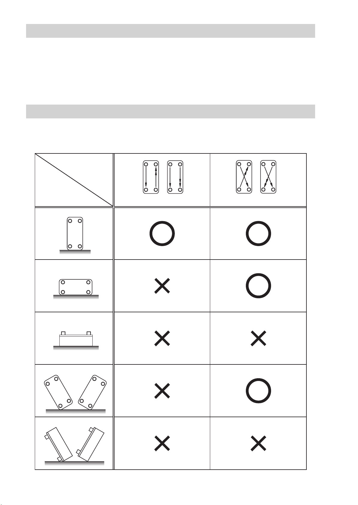
BHE should be used vertical installation for evaporator or condenser.
Sufficient performance may not be obtained other than vertical installation.
Install the control devices such as a solenoid valve at the flow channel inlet side.
If installing them at the outlet side, BHE may be damaged by pressure shock.
Install a strainer of mesh size 10 to 20 at the inlet side of BHE.
It is effective to prevent the clogging of BHE.
To prevent the fluid from freezing between the heat transfer plates.
• When starting operation, flow the hot fluid first, and then the cold fluid.
• When stopping operation, stop the cold fluid first, and then the hot fluid.
Do not use the cleaning chemicals frequently.
Use it only in case of decreasing the performance.
Frequent use may cause corrosion of BHE.
In case of using BHE as a heater, watch/control the operating condition to avoid the
scorching on the plates by:
• When starting operation, flow the cold fluid first, and then the hot fluid.
• When stopping operation, stop the hot fluid first, and then the cold fluid.
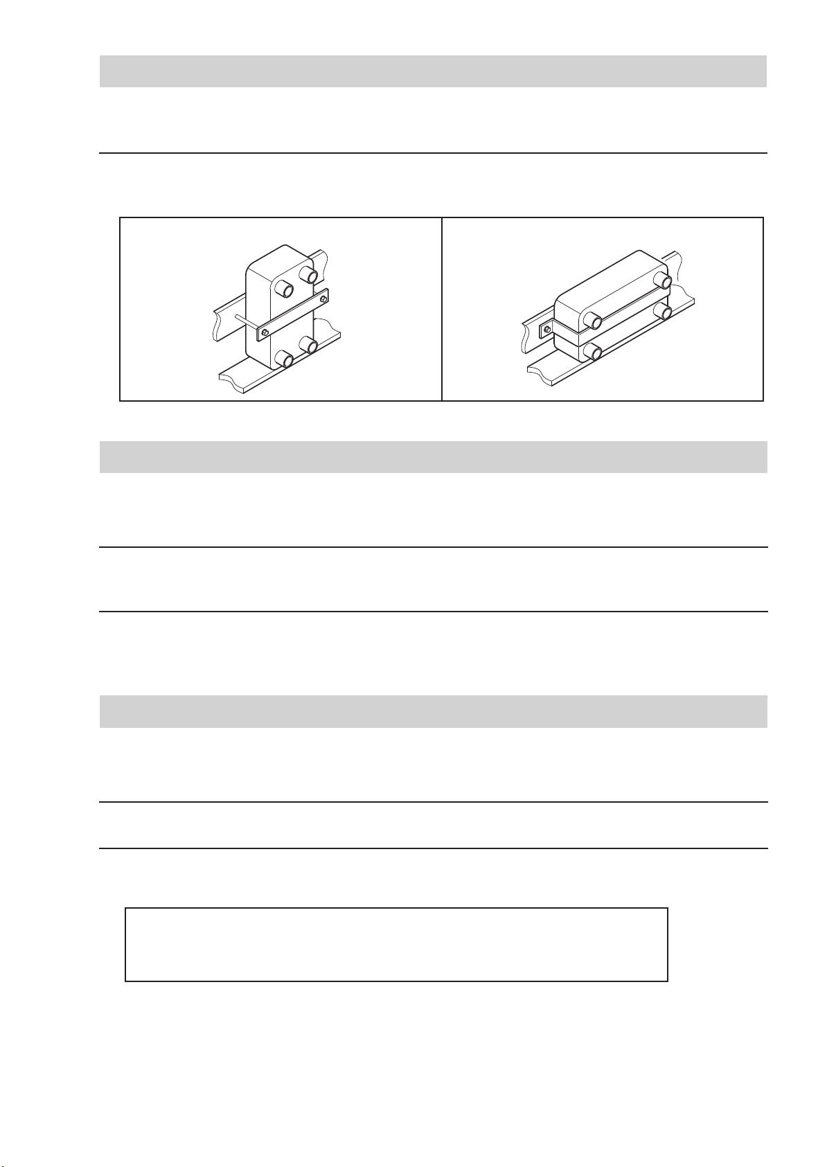
Avoid any load on the nozzles of BHE. The nozzles can be damaged by the load.
BHE itself or BHE nozzle might be damaged by a load from the piping/the control devices or
a load by thermal expansion of piping.
Support the piping so as to offset the load.
The durability of BHE can drop significantly in the operating conditions as shown below.
Contact Hisaka Works to check that BHE can be used.
•
Operation where the temperature difference of the hot fluid inlet and cold fluid inlet exceeds 80°C�
• Operation where there are frequent pressure fluctuations (pressure shock)
Avoid any vibration on BHE.
BHE itself or BHE nozzle might be damaged by a vibration. When installing and fixing BHE,
take appropriate measures such as providing support or suppressing the vibration.
4

Safety Precautions
CAUTION
Flow directions are as follows:.
•Refrigerant such a chlorofluorocarbons or ammonia on the primary side.
(Design pressure of the primary and secondary sides might differ depending on the model.)
•Upward for vaporized fluid such a refrigerant .
•Downward vapor and/or Gas to be condensed.
•If using for liquid-liquid applications, the fluid with a smaller temperature change should be
on the secondary side.
•Upward for fluids with high viscosity.
In the case of copper-brazed material, pay attention to the components of the chemicals.
Depending on the chemicals used, copper may be eluted, resulting in a significant reduction
in durability.
When cleaning the inside of BHE, keep the temperature difference as small as possible
during the cleaning process.
Repetition of rapid temperature change during cleaning may damage BHE.
If performing the leak test, pressurizing for a one side and the other side should be in
atmospheric condition.
If the test pressure is applied to both sides at the same time, any leakage cannot be detected.
If performing the pneumatic test for a one side, by submerging more than 5 minutes in
the water, bleed air sufficiently from the other none-pressurized side.
If air is not sufficiently bled, the remaining air might be confused for air leakage.
5

1. Structure of Brazed Plate Heat Exchanger
BHE consists of an S frame, heat transfer plates and E-frame as shown in the structural diagram on
the below. These components are brazed by copper and nickel materials.
●BHE Structure
No. Part Name Comment
Outlet/Inlet nozzle
S frame
E frame
Heat transfer plate
Brazed material
Name Plate label
Manufacturing
number
Shapes vary according to application.
Some models do not have an S frame and/or E frame.
Cannot be disassembled due to brazing.
Can be selected from copper or nickel materials.
Indication of BHE model and specifications
Serial number of BHE
Some models indicate this on E frame or plate.
Brazed copper and nickel have the following characteristics.
●Copper Brazed
Copper is an efficient bonding method for many industries like automotive and refrigeration.
Copper brazed heat exchanger is used for evaporator, condenser of refrigerant in the
compression refrigeration cycle and heater of hot water supply.
●Nickel Brazed
Nickel has special feature for corrosion resistance.
Nickel brazed heat exchanger is used for such as aqueous solutions of lithium bromide of
absorption chillers, fluid of ammonia chillers, and for purified water with a contamination problem
caused by elution of copper ions.
6

2. Before Using BHE
3. Operating Precautions
●Open the package delivered, and confirm the followings:.
•Check the name plate label on BHE to check that the delivered product is as ordered.
•Check that there is no damage on BHE.
•Check that all accessories, if ordered, are included.
Fixing brackets and mounting brackets are option, and normally not included.
Please prepare them by yourself.
If the delivered product is not as ordered, or is damaged, or if accessories are missing,
●Keep this instruction manual with care after reading it.
When reselling or transferring BHE, or when selling it as incorporated in another equipment, be
sure to attach this instruction manual.
●Carefully read also the instruction manuals for devices to be connected to BHE.
Pay attention also to the characteristics and handling instructions of fluids to be used.
●Strictly observe all laws and regulations corresponding to any other machinery/equipment
connected to BHE, and fluids that are used in each country where BHE is used.
●If there are questions regarding the contents of this manual and BHE, contact Sales Dept. of HFM.
●Be sure to fix BHE with reference to the fixing method examples shown in Section 6 "Fixing
Methods" (page 9). Brackets for fixing BHE are normally not included. Please prepare them by
yourself.
●The copyrights of this manual are owned by Hofmann (Beijing) Engineering Technology Co., Ltd.
●This manual is written in English and the customer must accept full responsibility for their
thorough understanding of the contents of this manual.
●Work with a suitable piping connection and method for the model of BHE.
Read Section 7 "Piping" (page 9) for details.
●BHE performs heat transfer by two fluids with a difference of temperature through individual
channels separated through plate.
It can be highly efficient heat transfer from hot fluid to cold fluid. BHE is used as heater, cooler,
evaporator, and condenser.
Do not use BHE for other purposes.
7

4. Storage/Installation Environment
5. Installation
●Storage/installation environment as BHE is free of deformation, rust, and corrosion should be avoided.
• Ambient environment:Avoid hot, humid, or freezing environment;
do not place any object on BHE; and so forth.
• Ambient temperature:-35°C to +80°C
• Ambient humidity :Relative humidity: 30% to 95% RH (no condensation)
●Use BHE in the installation orientation indicated by "○" in the table below.
If used in the orientation indicated by "×", BHE may suffer from problems such as fluid
accumulation and drifting, resulting in damage or failure in obtaining sufficient performance.
Flow direction
of product
Setting
Vertical
Horizontal
Lying back
Slanted①
Slanted②
Parallel flow Diagonal flow
Or
Or
8

6. Fixing Methods
●Read "Safety Precautions" (pages 3 to 5) carefully, and then fix BHE so that no load acts on BHE
or the nozzles and no vibration acts to BHE.
●Fix BHE with reference to the fixing methods shown in the figure below.
Fixing brackets are normally not included. Please prepare them by yourself.
Cross bar bracket and bolt Sheet metal bracket
7. Piping
●Read carefully the precautions on how to let the fluid flow described in "Safety Precautions"
(pages 3 to 5), and then connect the piping and the control devices.
●For information on the bore diameters and specifications of pipes connected to BHE, and on
the fluid flow direction and connection ports, refer to the assembly drawing.
●If you need to change the fluid connection ports shown in the assembly drawing, contact
Hisaka Works in advance, and check about the change.
●For the method and sequence of starting and stopping the operation, follow the precautions
described in "Safety Precautions" (pages 3 to 5).
●There is a possibility that the fluid might freeze after stopping operation in the environments
listed below.
•Cold regions
•As a cooler with a continuous flow of only low-temperature cooling medium.
•As a heater with a continuous flow of only low-temperature heating medium.
Discharge the fluid inside of BHE as soon as possible after stopping in order to prevent the fluid
from freezing.
●Remove the air sufficiently for a while after starting the operation.
8. Operation
9

9. Maintenance
●Visually check that no abnormality is found in appearance of BHE.
If rust occurs or brazing material is eluted, leakage may occur. Replace early BHE with a new one.
●During maintenance, flush the fluid at a rate of 1.2 times or more of operating flow rate to
discharge foreign materials from the inside of BHE. This can be made even more effective by
feeding in the compressed air at the same time.
●Remove BHE from the piping, and flow the chemicals from the primary or secondary nozzles to
clean BHE. The following cleaning method is recommended.
●Remove BHE from the piping, and strongly blow compressed air or fresh water from the fluid
outlet nozzles into BHE to flush out foreign materials from the inside.
Periodical Maintenance
Maintenance for decreasing of Flow Rate or Heat Transfer Performance, or increasing Pressure Drop
Example of chemicals
Acids
Alkalies
Aqueous Solution (Chemicals)
5% citric or oxalic acid aqueous solution
5% caustic soda aqueous solution
Cleaning Procedure
Process
Flushing
Flushing
Flushing
Acid cleaning
Alkaline
cleaning
Drying,
disinfection,
sterilization, etc.
Explanation
Flushing out for 20 to 40 minutes to completely replace the fluid with fresh water.
Circulate aqueous solution containing 5% citric acid or 5% oxalic acid at 30°C
to 60°C for 30 to 60 minutes.
* Adjust cleaning time so as to obtain an appropriate cleaning effect.
Perform flushing for 20 to 40 minutes to completely replace detergent with fresh water.
Circulate aqueous solution containing 5% caustic soda at 30°C to 60°C for 30
to 60 minutes.
* Adjust cleaning time so as to obtain an appropriate cleaning effect.
Depending on your conditions of use, such as evaporator, condenser, oil cooler,
or food equipment, provide processes such as a drying process, disinfection
process, and sterilization process.
Precautions in Cleaning
Points to Note in Cleaning
●For precautions in cleaning BHE, read "Safety Precautions" (pages 3 to 5).
●In order to improve the cleaning effect, the cleaning flow rate should preferably be as much
as possible. (Recommended flow rate: 1.2 times or more than operating flow rate)
●The cleaning-in-place (CIP) is normally performed by combining "acids" and "alkalies".
However, depending on your conditions of use, only the chemical which has s higher
cleaning effect may be selected.
Pressure Test and Leak Test
●For precautions in performing the pressure test or leak test of BHE, read "Safety Precautions"
(pages 3 to 5).
10

HFM Brazed Plate Heat Exchanger
Product Warranty
10. Warranty
For BHE model name, see the name plate label or the assembly drawing.
The Manufacturing Number is indicated on the S frame or E frame or end plate.
■Extent of Warranty
If any failure occurs in BHE while being used properly as a result of our manufacturing or engineering
problem, HFM will deliver the substitute BHE for BHE being failure at our responsibility.
The warranty covers the heat exchanger performance that HFM provides only as a single unit
used under the conditions based on the design specification, and not as "equipment" in which
BHE is incorporated.
■Warranty Period
The warranty period is one year from the date of delivery of BHE.
■Items Beyond Warranty
If the failure is caused by any of the following, it is not covered by the warranty even within the
warranty period.
●Failure caused by your improper handling or supervision during construction work after
delivery of BHE. (External damage of BHE, deformation or damage of nozzles by piping load
or connection work, etc.)
●Failure caused by not observing the various items described in "Safety Precautions" (pages 3 to 5).
●Failure caused by using the product under conditions different from the design specifications.
●Failure caused by natural disaster such as earthquake or fire.
■Exemption from Responsibility
HFM shall not be responsible for indirect damages caused by failure of this product.
(Costs of system repair, cost of fluid, countermeasures, etc.)
■Other
If you have special requirements other than the items listed in the assembly drawing and this
instruction manual, please contact HFM.
■Contact for Product Information
Hofmann (Beijing) Engineering Technology Co., Ltd.
TEL: +86 10 84478229 FAX: + 86 10 84478289
EMAIL: [email protected]
6F,East International Building, No.2 DongZhiMen Outside Street, DongCheng District, Beijing, 100027
BHE Model
Manufacturing Number
Date of Delivery Year: Month: Day:
11

Hofmann (Beijing) Engineering Technology Co., Ltd.
ISO9001:2015
Table of contents
Other Hofmann Industrial Equipment manuals
Popular Industrial Equipment manuals by other brands

Toro
Toro 04246 installation instructions

FLO-DYNAMICS
FLO-DYNAMICS BrakeMate Quick start instructions

Montanari
Montanari MGS19 Installation, use and maintenance

riverhawk
riverhawk IM-186 instruction manual

ZPA Pečky
ZPA Pečky MODACT MPS Mounting instructions

A.B.S.
A.B.S. Flexilo ECO Assembly-, Operating-, and Filling Instructions

Rohde
Rohde TE Series operating instructions

Siemens
Siemens SIRIUS S00 operating instructions

Hiltron security
Hiltron security PCM20 user manual

Balcrank
Balcrank BOBCAT 130 Series Service bulletin

Halton
Halton Max Ultra Circular Quick Guide for Commissioning

Festo
Festo CP-AM-MEAS Original operating instructions