Prozone PZ2-1 User manual
T.O3 NATURAL TECHNOLOGY
Reduces Chemical Usage,
Improves Sanitation
Produces Crystal Clear Water
Prozone Water Products: 2610 6th Street SW ·Huntsville, AL 35805 ·256-539-4570 ·www.prozoneint.com
Copyright 2007
PZ2-1 & PZ2-2 -
Ozone Generator Systems
INSTALLATION GUIDE and
OPERATION MANUAL
Commercial and Residential Pools & Spas
20348

2IMPORTANT SAFETY INSTRUCTIONS
Read and Follow All Safety Instructions
WARNING: Disconnect all power to pool equipment prior to installation, maintenance,
or removal of the PZ2.
WARNING: Do not permit children to operate this product
WARNING: To avoid risk of electric shock, fire, or injury, service should only be performed
by a qualified pool service professional.
WARNING: Installation must be performed in accordance with the National Electric Code
and any applicable local or state installation codes.
WARNING: When mixing acid with water, ALWAYS ADD ACID TO WATER, NEVER
WATER TO ACID.
SAVE THESE INSTRUCTIONS
P Z 2 - 1 & P Z 2 - 2
• Read and be familiar with this manual before installing, operating, or performing maintenance on the PZ2.
• Voltage must be determined before unit is installed.
• Replace damaged cord immediately.
• Do not bury cord.
• Connect only to a properly grounded, grounding type receptacle.
• Install at least 5 feet from the inside wall of the pool using non-metallic plumbing. The ozone generator is to be
located one foot above the maximum water level to prevent water from contacting electrical equipment. Install to
provide drainage of compartment for electrical components.
• A pressure wire connector is provided in the control box inside the unit to permit connection of a minimum No. 8
AWG solid copper bonding conductor between this point and any metal equipment, metal enclosures of electrical
equipment, metal water pipe, or conduit within 5 feet of the unit as needed to comply with local requirements.
• Wear safety glasses when drilling and tapping holes for installation of unit.
WARNING: Short term inhalation of high concentrations of ozone and long term inhalation of low concentrations of ozone
can cause serious harmful physiological effects. Do not inhale ozone gas produced by this device.
NOTE: The instructions in this document provide general installation guides. Consult your dealer for specific installation instructions.
Additional information is available at www.prozoneint.com. Check system for any visible shipping damage. If damage has occurred,
contact the delivery company and your dealer immediately. Before beginning installation, please turn to the Installation Kit Inventory
Section and verify that all listed parts are on hand.
Tools Needed: Cordless Power Drill, Screw Driver, Adjustable Wrench, Pliers, Wall Mount Screw Anchors, Knife
P Z 2 - 1 & P Z 2 - 2
Installation
3
INTRODUCTION TO OZONE
Ozone (O3) is generated by irradiating air or oxygen (O2) with ultraviolet radiation. Ozone is a molecule of oxygen that is formed when
three atoms of oxygen are bound together instead of the normal two atoms. The extra oxygen atom makes ozone the most powerful
oxidizer and sanitizer readily available.
Since ozone is unstable and quickly decomposes to normal oxygen under normal conditions, it cannot be shipped or stored. Therefore,
it must be manufactured on site for immediate use. In normal air it lasts about an hour. In normal pool water it lasts just long enough to
purify the water - less than 1 second.
Although ozone is mainly thought of as a sanitizer, it acts primarily as an oxidizer in the pool environment. In a typical pool run on
chlorine only, up to 90 percent of the chlorine may be used up in reactions unrelated to disinfection. The byproducts of these reactions
are combined chlorines. Combined chlorines are the cause of eye irritation, odor, and the other unpleasant side effects of chlorination.
When ozone is used, it oxidizes a large portion of the contaminants (usually referred to as bather load) which result in the formation of
combined chlorines. The result is that more chlorine is available for disinfection and less chlorine is required to maintain the pool.
Ozone also provides some disinfection, but an ozone residual cannot be established, so the use of chlorine or bromine is always
recommended.
PREPARING FOR INSTALLATION
1. Install your PZ2-1 or PZ2-2 Ozonator so that dust, sand, debris, chemicals, or other foreign objects are not sucked into the
compressor's intake fan or hose (if equipped with Noise Attenuator).
2. Check electrical system: 240VAC double switched per N.E.C. standards; 120VAC single switched.
3. Check for Suction Line Check Valve. Equipment may draw if no check valve is present.
4. Balance the pH.
5. Backwash the filter.
6. Shock the pool with a non-lithium-based material. The use of Calcium Hypochlorite or Sodium Hypochlorite is recommended.
The Table below summarizes the levels that are recommended by The Association of Pool and Spa Professionals
(APSP). It is important to maintain these levels in order to prevent corrosion or scaling and to ensure maximum enjoyment
of the pool. Test your water periodically. Take a water sample in to be professionally tested by a Pool and Spa
Professional at least once a month. See our web site for more information on Basic Pool Water Chemistry.
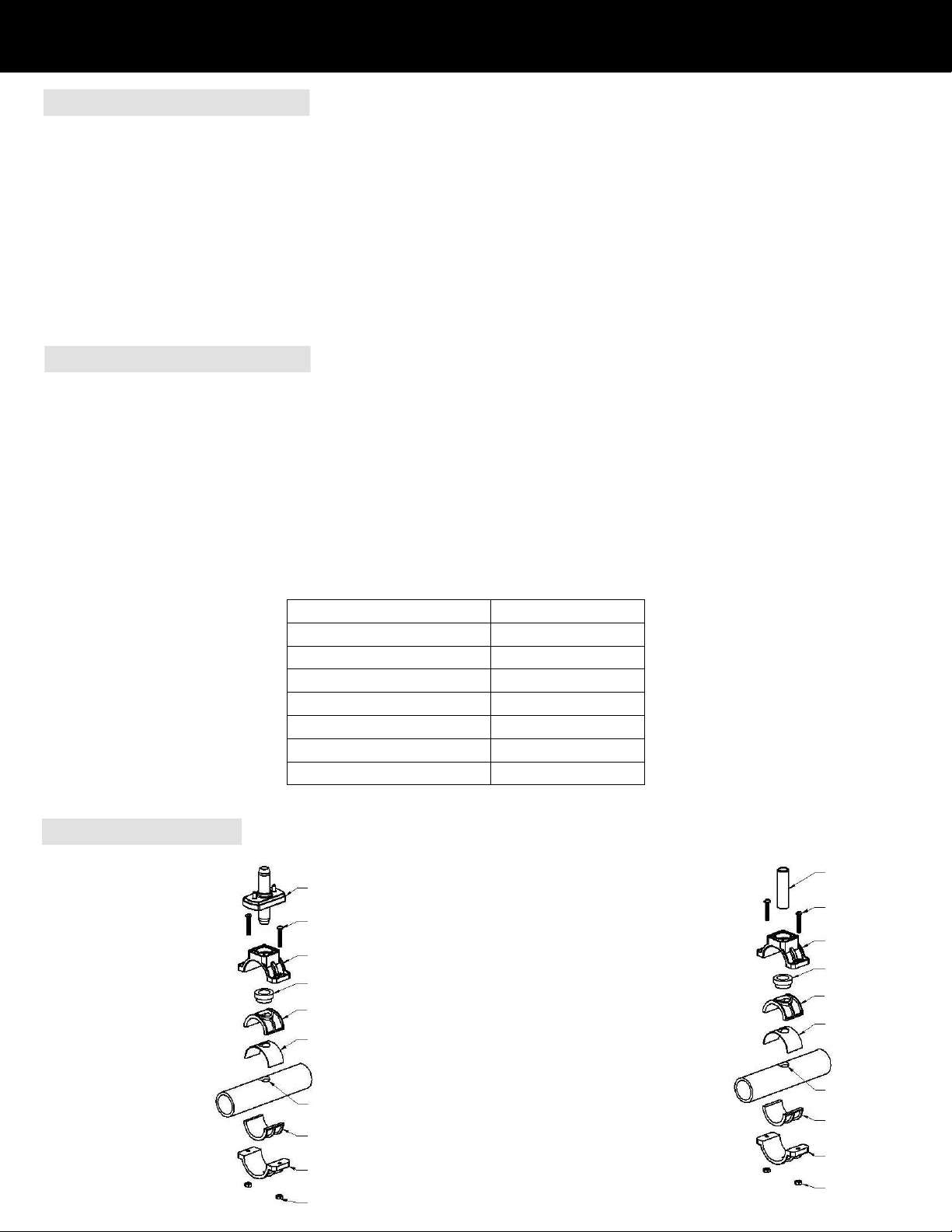
pH 7.2 – 7.6
Alkalinity 80 – 120 ppm
TDS < 1,000
Cyanuric Acid 30 – 70 ppm
Free Chlorine 0.5 – 1.5 ppm
Calcium Hardness 60 – 400 ppm
Metals 0 ppm
Nitrates / Phosphates < 30 ppm
SADDLE CLAMP ASSEMBLY
Note: For 2” pipe, do not use 1-1/2” adapters
and gasket and turn Bushings so small end
points toward Injector (for Entrance)
or PVC Pipe (for Exit).
For bypass Entrance, (before Ball Valve)
Using 1-1/2” pipe, Assemble:
Venturi Injector (Note direction)
Saddle Clamp Top & Bottom
Top & Bottom Adapters
Bushing (Note direction)
Gasket
Screws (2)
Nuts (2)
For bypass Exit, (after Ball Valve)
Using 1-1/2” pipe, Assemble:
PVC Pipe
Saddle Clamp Top & Bottom
Top & Bottom Adapters
Bushing (Note direction)
Gasket
Screws (2)
Nuts (2)
VenturiInjector(600207)Screw(2)(201863)SaddleClampTop(201155-4)SaddleClampBottom(201155)Bushing(201155-5)TopAdapter(201155-2)BottomAdapter(201155-3)Gasket(400076)7/8”Dia.Hole1/4-20Nut(2)(20703)PVCPipe(20314)Screw(2)(201863)SaddleClampTop(201155-4)SaddleClampBottom(201155)Bushing(201155-5)TopAdapter(201155-2)BottomAdapter(201155-3)Gasket(400076)7/8”Dia.Hole1/4-20Nut(2)(20703)
4
P Z 2 - 1 & P Z 2 - 2
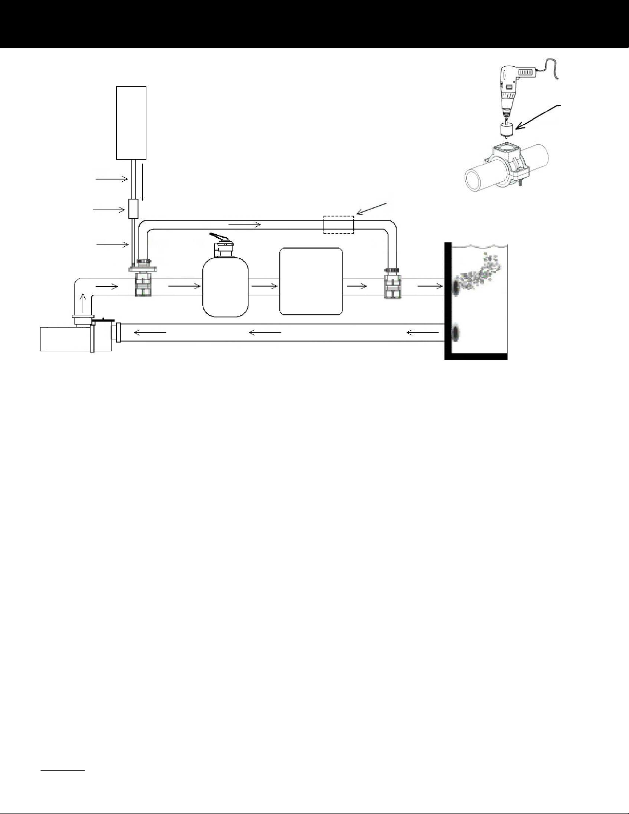
Bypass / Venturi Injection Installation
CAUTION: Make sure the voltage is the same as prescribed on the side of the Prozone ozone generator. Overvoltage will void
customer warranty.
Pump
PZ2
Filter Heater
Pool
Saddle Clamp
Assembly
¾” Hose
Saddle Clamp
Assembly
Check Valve
¾” Ball Valve
(If using a DE filter)
F
l
o
w
¼” Hose
¼” Hose
1. Turn pump OFF.
2. Locate section of existing plumbing in which you choose to install the ENTRANCE leg of the bypass. Location should be in any
accessible area after the pump, but before the filter.
3. Install Saddle Clamp Top & Bottom, (and adapters if needed), without Bushing, (this will be used as a guide for your installation hole).
4. Drill a 7/8” hole through one wall of the pipe, using power drill, being careful not to drill too deep to avoid penetrating the opposite side
of the plumbing.
5. Locate section of existing plumbing in which you choose to install the EXIT leg of the bypass. Location should be in any accessible
area after the filter, and heater (if equipped).
6. Repeat steps 3 & 4.
7. Remove both Saddle Clamp Assemblies.
8. Using components listed, mount one Saddle Clamp Assembly on Entrance bypass location with the INLET side of the Venturi Injector
mounted in the Saddle Clamp Bushing, (ozone ports should be facing upward).
9. Using components listed, mount the other Saddle Clamp Assembly on Exit bypass location with the ½” x 3” PVC pipe mounted in the
Saddle Clamp Bushing.
10. Attach one end of ¾” clear hose to Venturi Injector and secure with a metal clamp. Attach other end of ¾”clear hose to ½” x 3” PVC
pipe and secure with a metal clamp.
11. Mount the PZ2 Ozone Generator vertically on wall with compressor at lower end, using two holes in rain shield. Place system at or
above water level. If unit must be mounted below water level, loop the hose so that at some point it is above water level (a solenoid
control valve may be necessary).
12. Apply Teflon tape to the threads of a ½” MPT x ¼” HB fitting, part number 20230, and screw into the end of the Check Valve that has
the spring in it, (This is the INLET side of the Check Valve). Mark this end as “INLET”.
13. Apply Teflon tape to the threads of a ½” MPT x ¼” HB fitting, part number 20230, and screw into the opposite of the Check Valve,
(This is the OUTLET side of the Check Valve). Mark this end as “OUTLET”.
14. Cut a 6 inch length of ¼” hose and connect one end to the OUTLET side of the Check Valve and connect the other end to the open
ozone port (Marked #1) on the Venturi Injector. Secure with ½” plastic clamps.
15. Cut a length of ¼” hose long enough to reach between the Ozone Generator and the Check Valve.
16. Attach one end of the ¼” hose to the Ozone Generator and connect the other end to the INLET side of the Check Valve. Secure with
½” plastic clamps.
17. Slip the M09 Noise Attenuator onto the 1” fitting at the rear of the PZ2 (if equipped) (Installation manual supplied with M09).
18. Electrical Installation: System is either 120 or 240 VAC, 50/60 HZ. Wire Prozone Ozone Generator system to circulation pump switch orr
timer. Prozone system and circulation pump should be started simultaneously. Use N.E.C. or local code grounding and installation
procedures for swimming pool equipment.
Note: If using a Diatemateous Earth filter, install a ¾” ball valve in the ¾” hose to the output side of the venturi, as shown.
7/8” Hole Saw
5
P Z 2 - 1 & P Z 2 - 2
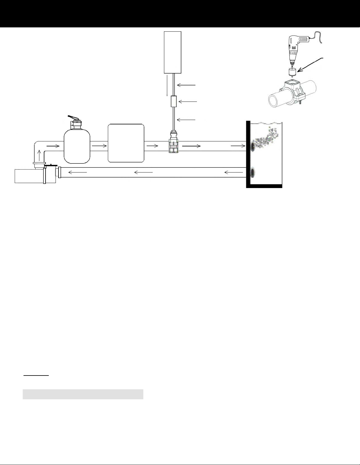
Direct Injection Installation
NOTE: There must be at least four feet of return line between the point where the ozone bubbles are injected and the pool. If there is
not four feet of return available, a flexible loop can be added to the return line.
CAUTION: Make sure the voltage is the same as prescribed on the side of the Prozone ozone generator. Overvoltage will void
customer warranty.
PZ2 SERIES OZONE GENERATOR OPERATION
The Prozone system works when air is drawn across a high-energy vacuum ultraviolet (VUV) lamp, converting some air to ozone. The
ozone is introduced into the water either by direct injection or through a bypass venturi system. For direct injection, the venturi injector
is inserted directly into the return line of the pool creating a suction (vacuum) that draws the ozone into the venturi as the water returns
to the pool. The bypass venturi system takes water directly after the circulation pump (highest pressure point), bypasses part of the
water flow past filters, heater, etc. through a venturi injector, through contact tubing and then returns the water back to the pool return
line. A check valve is employed to prevent water backup in the event of system failure. The system should be run 6-8 hours per day for
best effect. Run time may vary depending on usage.
Pump
Filter Heater
Pool
PZ2
Saddle Clamp
Assembly
Check Valve
¼
” Hose
F
l
o
w
1. Turn pump OFF.
2. Locate section of existing plumbing in which you choose to install the Direct Injection Saddle Clamp Assembly. Location should be in
any accessible area after the pump, filter, and heater, (if equipped).
3. Install Saddle Clamp Top & Bottom, (and adapters if needed), without Bushing, (this will be used as a guide for your installation hole).
4. Drill a 7/8 ” hole through one wall of the pipe, using a power drill, being careful not to drill too deep to avoid penetrating the opposite
side of the plumbing. Remove the Saddle Clamp Assembly.
5. Apply Teflon tape to male threads of (2) fittings, part numbers 20230 and 20303. Assemble all (3) fittings, 20230, 20303, and 201669,
and glue to 3” long PVC pipe, part number 20314. Allow glue to dry for at least 10 minutes.
6. Using components listed, mount the Saddle Clamp Assembly, and insert the 3” PVC pipe assembly, (Step 5), into the Saddle
Clamp Bushing and tighten both screws.
7. Mount the PZ2 ozone generator vertically on wall with compressor at lower end, using two holes in rain shield. Place system at or
above water level. If unit must be mounted below water level, loop the hose so that at some point it is above water level (a solenoid
control valve may be necessary).
8. Apply Teflon tape to the threads of a ½” MPT x ¼” HB fitting, part number 20230, and screw into the end of the Check Valve that has
the spring in it, (This is the INLET side of the Check Valve). Mark this end as “INLET”.
9. Apply Teflon tape to the threads of a ½” MPT x ¼” HB fitting, part number 20230, and screw into the opposite of the Check Valve,
(This is the OUTLET side of the Check Valve). Mark this end as “OUTLET”.
10. Cut a 6 inch length of ¼” hose and connect one end to the OUTLET side of the Check Valve and connect the other end to ozone
fitting on the 3” PVC pipe assembly. Secure with ½” plastic clamps.
11. Cut a length of ¼” hose long enough to reach between the Ozone Generator and the Check Valve.
12. Attach one end of the ¼” hose to the Ozone Generator and connect the other end to the INLET side of the Check Valve. Secure with
½” plastic clamps.
13. Slip the M09 Noise Attenuator onto the 1” fitting at the rear of the PZ2 (if equipped) (Installation manual supplied for M09).
14. Electrical Installation: System is either 120 or 240 VAC, 50/60 HZ. Wire Prozone Ozone Generator system to circulation pump switch or
timer. Prozone system and circulation pump should be started simultaneously. Use N.E.C. or local code grounding and installation
procedures for swimming pool equipment. .
¼
” Hose
7/8” Hole Saw
6
P Z 2 - 1 & P Z 2 - 2
Inventory Lists & Troubleshooting
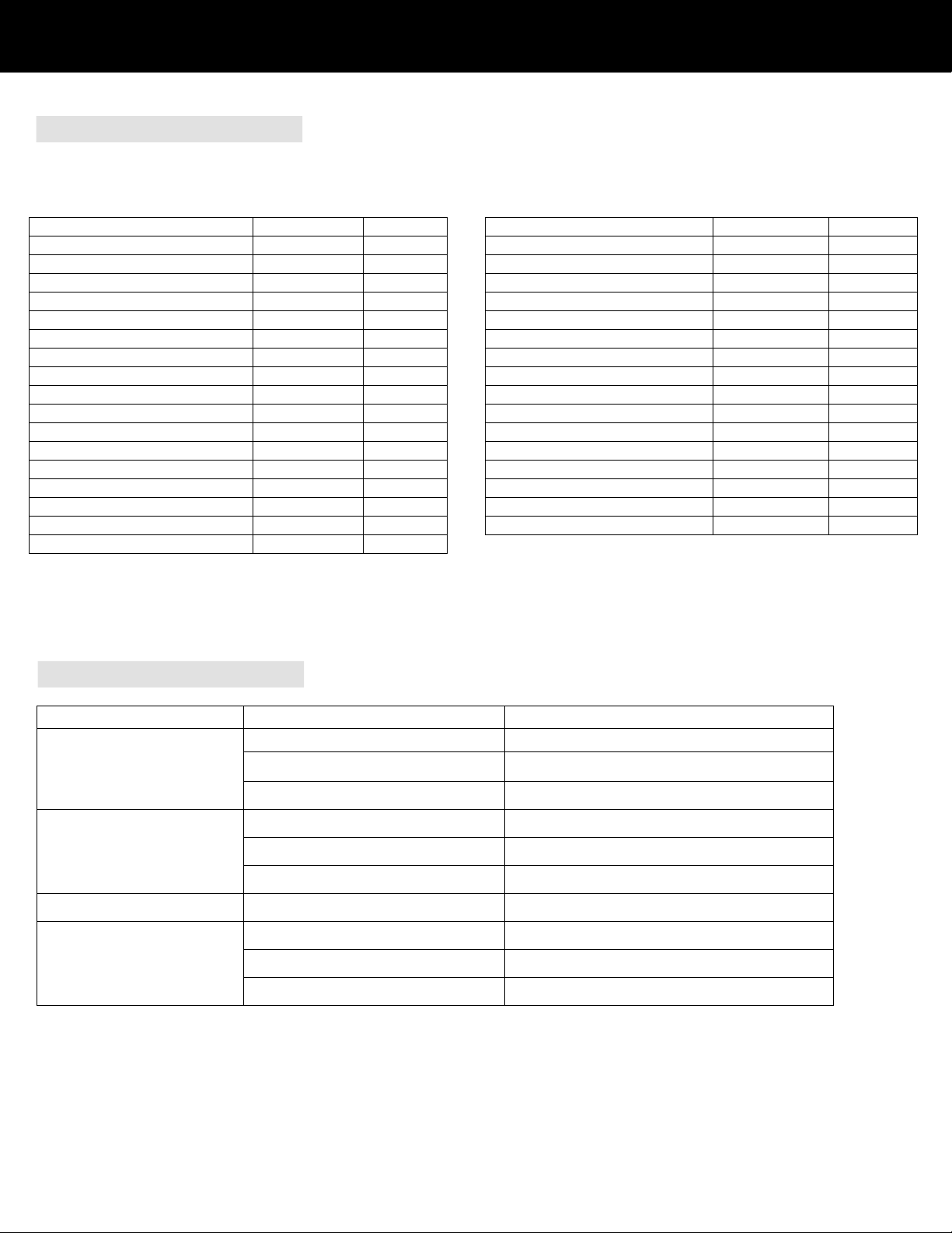
INSTALLATION KIT INVENTORY
TROUBLESHOOTING GUIDE
PROBLEM
PROBABLE CAUSE
REMEDY
Loose wiring
Check all wiring connections
No power to unit
Check voltage compatibility
Check power source
No light from Prozone unit
Defective lamp or other internal component
Return unit to dealer
Excessive back pressure
Check for kinks or clogs in hose or plumbing
Leak in fitting
Replace fitting
No bubbles from injector or
no evidence of ozone in pool
Filter not working
Check filter
Water in Ozone Generator
Check Valve failure
Verify Check Valve in Venturi is operating properly
Water chemistry out of balance
Check readings and balance accordingly
Total Dissolved Solids (TDS) level too high
Refer to dealer for proper water testing
Cloudy water; foamy water; scum
Filter not working
Clean or replace filter
NOTE: Cloudy water may occur when the ozone generator is started. Filter and backwash as necessary.
P20 Installation Kit
PZ2-1 & PZ2-2 Series with Bypass / Venturi Injector
Description
Part Number
Quantity
784 Venturi Injector
600207
1
Plastic Clamp ½”
20185
4
Metal Clamp 1¼”
20067
4
Polybraid Hose ¼”
20260
72”
Clear Hose ¾”
20264
96”
PVC Pipe ½” x 3”
20314
1
Fitting ½” MPT x ¼” HB
20230
2
Check Valve ½”
20215
1
Saddle Clamp, Outer Top
201155-4
2
Saddle Clamp, Outer Bottom
201155
2
Saddle Clamp, Inner Top
201155-2
2
Saddle Clamp, Inner Bottom
201155-3
2
Saddle Clamp Gasket
400076
2
Saddle Clamp Bushing
201155-5
2
Screw #14 x 1-½” PPMS
201863
4
Nut ¼-20
20703
4
D03 Installation Kit
PZ2-1 & PZ2-2 Series with Direct Injection
Description
Part Number Quantity
Plastic Clamp ½”
20185 4
Polybraid Hose ¼”
20260 120”
Fitting ½” MPT x ¼” HB
20230 3
PVC Fitting ¾” MPT x ½” FPT
20303 1
PVC Fitting ¾” FPT x ½” SL
201669 1
PVC Pipe ½” x 3”
20314 1
Check Valve ½”
20215 1
Saddle Clamp, Outer Top
201155-4 1
Saddle Clamp, Outer Bottom
201155 1
Saddle Clamp, Inner Top
201155-2 1
Saddle Clamp, Inner Bottom
201155-3 1
Saddle Clamp Gasket
400076 1
Saddle Clamp Bushing
201155-5 1
Screw #14 x 1-½” PPMS
201863 2
Nut ¼-
20 20703 2
Note: For pools with Diatomaceous Earth filter and Bypass / Venturi Injector installation, add (1) ¾” Ball Valve, (2) ¾” MPT x HB fittings,
and (2) 1 ¼” metal clamps.
This manual suits for next models
1
Table of contents
Other Prozone Industrial Equipment manuals


Popular Industrial Equipment manuals by other brands


Premier
Premier 240 COUPLING Installation, Inspection, Operation & Maintenance Guide

Giebel
Giebel Adsorber Vario VG Assembly and maintenance manual

Duro Dyne
Duro Dyne LS-5 owner's manual

Telegärtner
Telegärtner NRT 1 EX G3 Mounting and installation instructions

ABB
ABB HT608780 Operation instructions

PISCO
PISCO VTA Series instruction manual

Bushranger
Bushranger SNATCH BLOCK quick start guide

Carstens Amplification
Carstens Amplification AG501 Setup

Sungrow
Sungrow MVS6250 Transportation and Installation Guide

KYOKUTOH
KYOKUTOH KIKK Series Teaching Guide Instruction Manual

Reflex
Reflex Servitec 35 operating manual

Renishaw
Renishaw InfiniAM Spectral user guide