EMUGE Speedsynchro Mini User manual

Speedsynchro®Mini
Speedsynchro®Mini
Operating instruction

Speedsynchro®Mini
2 Operating instruction edition: 13.09.2022
Contents:
1Application range, safety instructions and technical data............................. 4
1.1 Application range, determined use............................................................................................. 4
1.2 Specifications ............................................................................................................................. 5
1.3 Safety instructions and hints ...................................................................................................... 6
1.4 Proprietary rights ........................................................................................................................ 6
1.5 Dimensions and technical data .................................................................................................. 7
2Putting the Speedsynchro®Mini into operation.............................................. 8
2.1 Unpacking................................................................................................................................... 8
2.2 First putting into operation / preparation..................................................................................... 8
Locking block already mounted on the machine ............................................................. 9
Mounting of the machine-side locking block on the spindle block................................. 10
2.3 Programming notes.................................................................................................................. 12
2.4 Re-putting into operation.......................................................................................................... 13
2.5 Sealing disk / cooling disk ........................................................................................................ 14
Application ..................................................................................................................... 14
Assembly of the sealing disk or cooling disk................................................................. 14
2.6 Collets....................................................................................................................................... 15
Application ..................................................................................................................... 15
Assembly of the collet.................................................................................................... 15
2.7 Assembly of the tap/cold-forming tap....................................................................................... 16
............................................................................................................................................................... 16
2.8 Remove the tap/cold-forming tap, the clamping nut and the sealing disk................................ 17
3Readout operating data via NFC interface..................................................... 18
3.1 Speedsynchro- Electronics................................................................................................... 18
3.2 Readout operating data............................................................................................................ 18
3.3 Display in the app..................................................................................................................... 19
4Maintenance / Servicing .................................................................................. 21
4.1 Maintenance schedule.............................................................................................................. 21
4.2 External cleaning...................................................................................................................... 21
4.3 Maintenance............................................................................................................................. 21
5Storage when not in use.................................................................................. 22
6Disposal instructions....................................................................................... 22
7EU-Declaration of Conformity......................................................................... 23
8UK Conformity Assessed................................................................................ 24
9FCC-Rules......................................................................................................... 25
Speedsynchro®Mini
Operating instruction edition: 13.09.2022 3
Warnings, symbols
In this operating instruction the following symbols are used:
Attention
Marks special instructions, rules and prohibitions, which are important in order to avoid
any damage.
Please observe these instructions!
Note
Marks application instructions and other useful information.
Sectional view:
Speedsynchro® Mini
Attention
Battery:
Not rechargeable
Do not incinerate
Dispose of as prescribed. Please refer to chapter 6, page 22.

Speedsynchro®Mini
4 Operating instruction edition: 13.09.2022
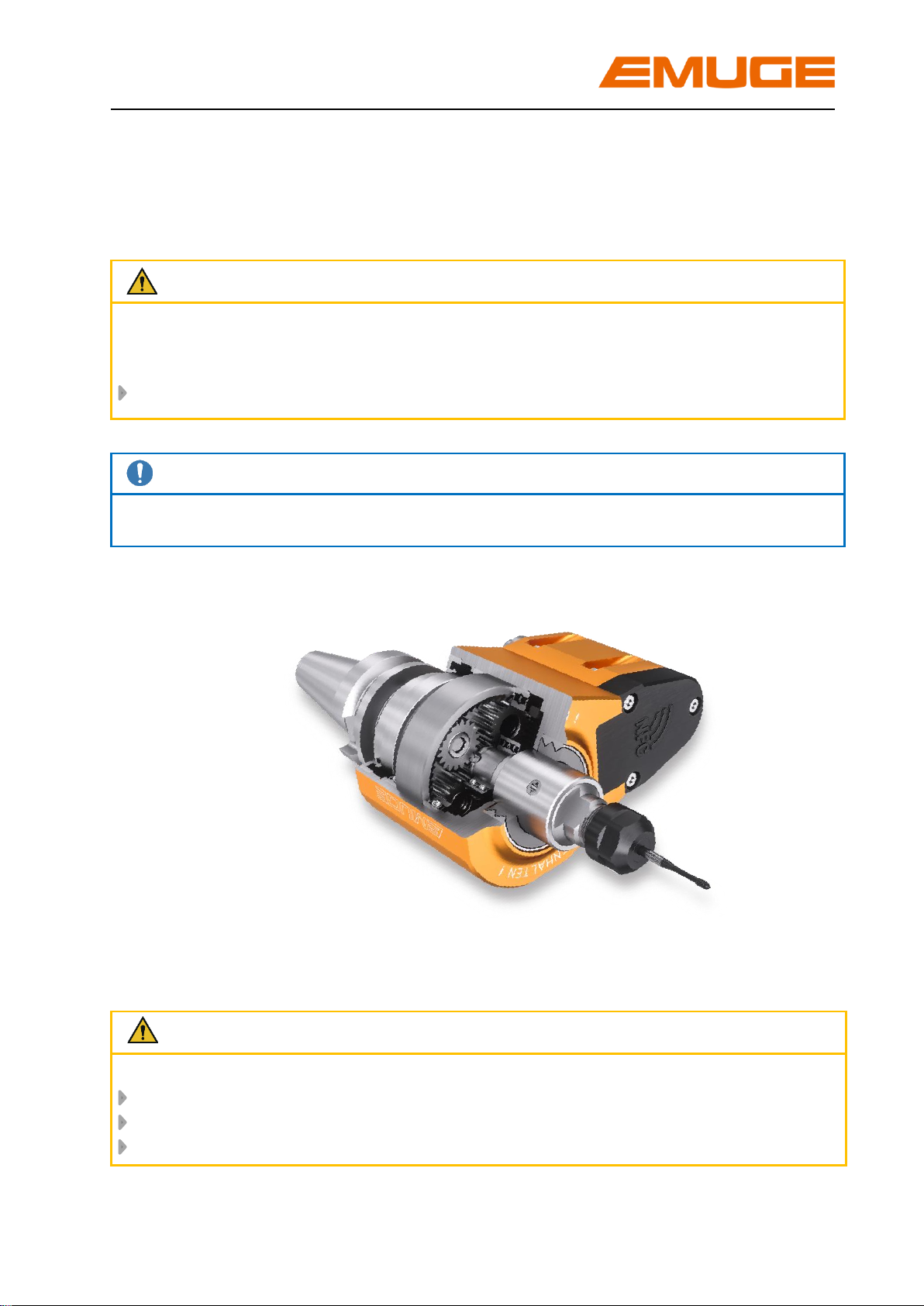
1 Application range, safety instructions and technical data
1.1 Application range, determined use
The collet holders type Speedsynchro®Mini are used on CNC-machining centers with
synchronous control. They are intended for clamping of taps/cold-forming taps for
thread production.
Normally the Speedsynchro®Mini are equipped with the following shank:
BT 30 (DIN) ISO 7388-2 JD
Applicable for cutting range M1 –M6, please refer to Table 1, page 7.
The tap/cold-forming tap is locked via the collets according to DIN ISO 15488.
The collets must be chosen depending on the used type and used tap/cold-forming
tap, for more information please refer to chapter 2.6, page 15.
The collet holders type Speedsynchro®Mini are designed for coolant-lubricant
pressure up to 70 bar.
For correct use, the Speedsynchro® Mini must be secured against twisting in the
machine spindle. This requires a stop fixture adapted to the machine-side locking
block. For further details, please refer to chapter 2.2 page 8.
The non-determined use exempts the manufacturer from any liability.

Speedsynchro®Mini
Operating instruction edition: 13.09.2022 5
1.2 Specifications
Further characteristics of the Speedsynchro®Mini:
The Speedsynchro®Mini uses an integrated gear ratio of 1:4,412. (This enables the
machine spindle to be operated in a lower speed range, thus saving energy.)
The integrated minimal length compensation on tension and compression
compensates arising minimal pitch differences between synchronous spindle and
tap/cold forming tap possibly leading to high thread flank friction forces. A possible
increase of axial force during the thread producing cycle is reduced to a minimum.
The resulting advantages are:
- no mis-cutting of the threads
- optimized tool life of tap/cold-forming tap
The Speedsynchro®Mini has an NFC-Modul (NFC = Near Field Communication)
with integrated electronics. This takes and stores the operating data. An NFC-
enabled smartphone is required to read out the data (not included in the delivery).
For further details please refer to chapter 3, page 18.
Simple programming as synchronous cycle with feed programme adapted to the
transmission ratio.
The reversal of the tap/cold-forming tap is done by the machine spindle:
- no switching components in the Speedsynchro®Mini
- low wear and longer maintenance intervals
High changing speeds are possible due to the low weight (< 2 kg) and the compact
design.

Speedsynchro®Mini
6 Operating instruction edition: 13.09.2022
1.3 Safety instructions and hints
For all works, i.e. putting into operation, production or maintenance, please observe
the details given in the operating instruction.
All relevant safety regulations as well as local instructions are to be observed when
working.
Below please find some basic rules:
Attention
Please wear gloves during tool change to avoid injury.
Basically change the tool yourself to avoid the sudden start of the spindle
caused by mis-operating.
Hold the tool when loosening the tool clamping to avoid it falling down and
damaging the tool and the work piece.
Keep the tool adaptation clean.
There are maximum values for cutting speeds and feeds for every kind of
machining. Please observe such data.
Please observe the maximum tool dimensions.
Furthermore, the instructions of the tool manufacturers are valid!
1.4 Proprietary rights
The entire contents of these operating instructions are subject to German proprietary
rights legislation.
Any form of multiplication, processing, broadcasting, passing on to third parties - also
in the form of extracts - and any kind of use outside the boundaries of proprietary rights
requires the written consent of EMUGE GmbH&Co.KG.
Speedsynchro®Mini
Operating instruction edition: 13.09.2022 7
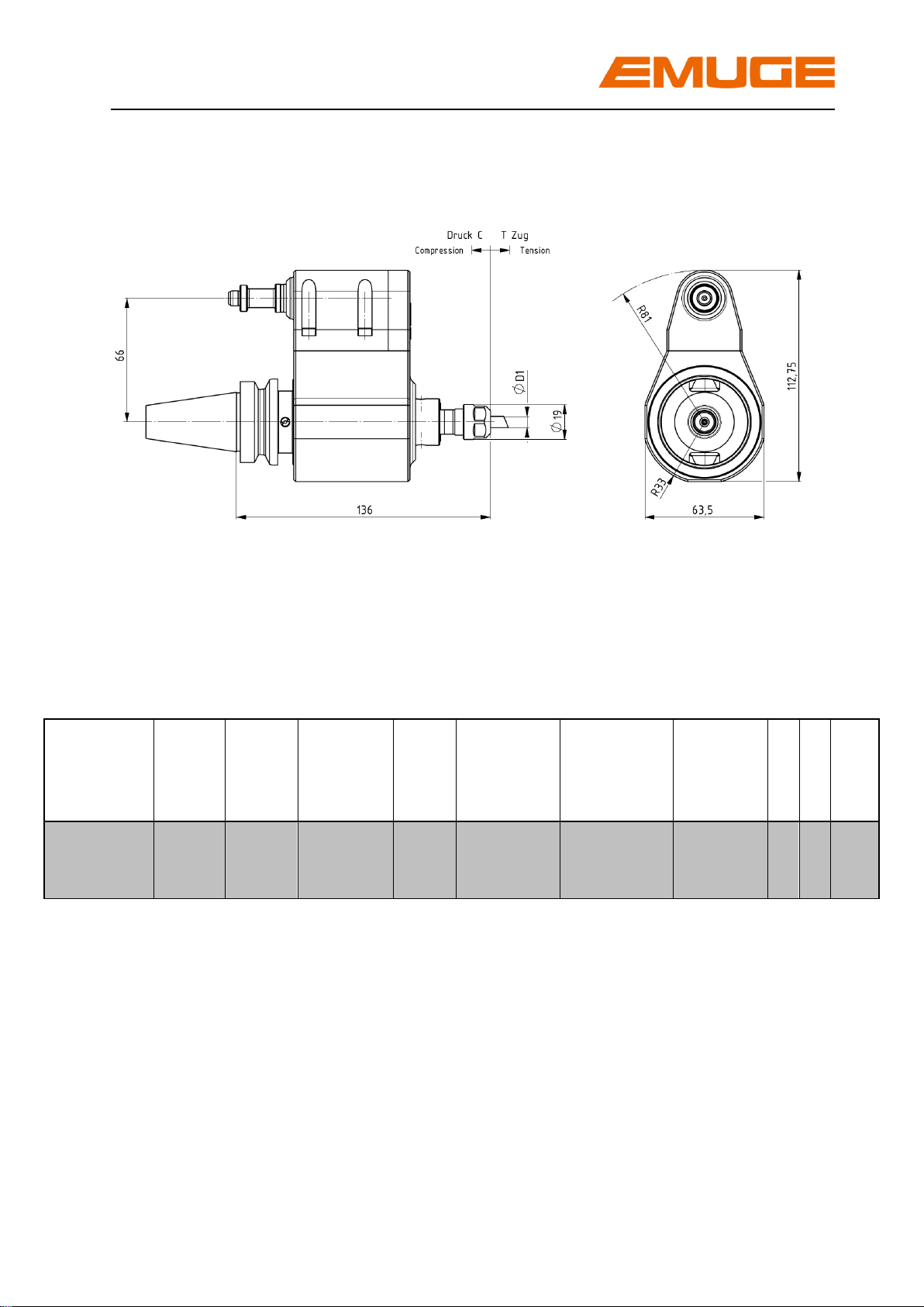
1.5 Dimensions and technical data
Picture 1: Dimensions of Speedsynchro®Mini
Table 1: Technical data of Speedsynchro®Mini
Type
Article
number
Cutting
range
Clamping
range
Ø D1 [mm]
Collet
size
max.
spindle
speed
[min –1/rpm]
Transmission
ratio
Shank
connection
C
T
P
max.
[bar]
Speedsynchro
® Mini
F3720I90
M1 –M6
2,5 –6
ER 11
(GB)
2700
1:4,412
BT30
ISO 73882
JD
0,5
0,5
70

Speedsynchro®Mini
8 Operating instruction edition: 13.09.2022
If necessary, turn the
shank until the stop fixture
engages
Alignment of the two
grooves
Picture 2
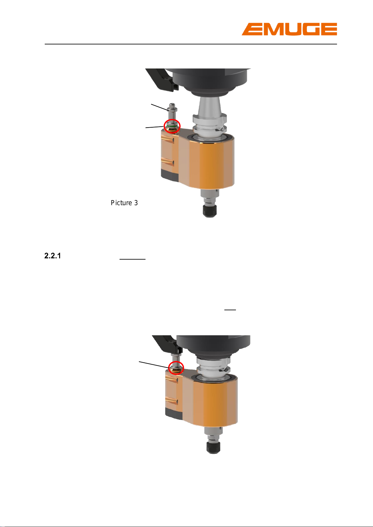
2 Putting the Speedsynchro®Mini into operation
2.1 Unpacking
Take the Speedsynchro®Mini from the packing
Clean the Speedsynchro®Mini with a duster to remove any conservation oil
Note
Do not use any aggressive solvents.
Do not use fibrous materials i.e. steel wool
2.2 First putting into operation / preparation
Note
The angel position of the Speedsynchro® Mini stop fixture is not adjustable.
The position of the machine-side locking block at the spindle is adjusted to the stop
fixture of the Speedsynchro® Mini during initial assembly.
Hook the Speedsynchro® Mini manually into the designated magazine tool
slot. Make sure that the stop fixture is engaged in the angular position, please
see Picture 2. Green marking ring is visible, please see Picture 3,page 9.
Attention
The housing of the Speedsynchro®Mini must be secured against twisting via stop fixture.
For the use of the Speedsynchro® Mini the machine-side locking block must be mounted.
Speedsynchro®Mini
Operating instruction edition: 13.09.2022 9
Picture 3
Locking block already mounted on the machine
Insert the Speedsynchro® Mini into the spindle at the slowest speed of the
tool changer.
Check the correct position of the machine-side locking block.
Fixing bolt is engaged green marking ring is not visible, please see
Picture 4.
Picture 4
Green marking ring
Fixing bolt
Fixing bolt is engaged –green
marking ring not visible.
Spindle can be rotated.
Speedsynchro®Mini
10 Operating instruction edition: 13.09.2022
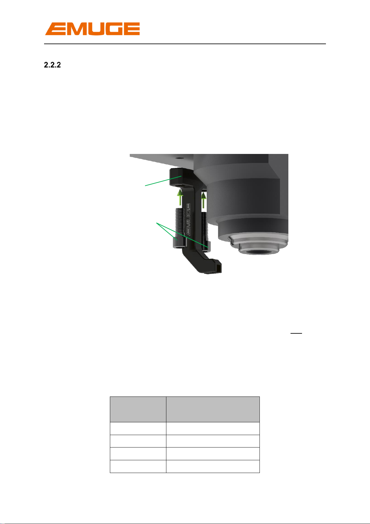
Mounting of the machine-side locking block on the spindle block
Mount the machine-side locking block hand-tight with two hexagon socket
screws.
The mounting threads on the spindle head are located on the side facing away
from the machine door, M6, M8, M10, or M12, depending on the machine.
Reducing sleeves are available as accessories for M6 and M8, please order
these separately.
Picture 5
Insert the Speedsynchro® Mini into the spindle at the lowest speed of the tool
changer.
Check the correct position of the fixing bolt green marking ring is not
visible, please see Picture 4, page 9.
Tighten the mounting screws on the machine-side locking block.
Table 2: Tightening torques of the mounting screws
Dimension
Recommended tightening
torque
M 6
10,5 Nm
M 8
25 Nm
M10
47 Nm
M12
78 Nm
Hexagon socket screws
Machine-side locking block

Speedsynchro®Mini
Operating instruction edition: 13.09.2022 11
Replace the Speedsynchro® Mini via tool changer.
Insert the Speedsynchro® Mini again via the tool changer at slowest speed
and check the correct position of the stop fixture.
Note
For series use, please observe the programming instructions, chapter 2.3, page 12.

Speedsynchro®Mini
12 Operating instruction edition: 13.09.2022
2.3 Programming notes
The transmission ratio of the Speedsynchro®Mini is 1:4,412.
This results in the following programming guidelines.
Feed f
Rotational speed n of the machine spindle for the desired tool speed
Attention
The maximum speed at the machine spindle is: nMSP = 2.700 rpm
The maximum speed at the tool is: nTOOL = 11.912 rpm
Example: thread M2 / pitch P = 0,4 mm:
Desired rotational speed of threading tool:
nTOOL = 11.000 rpm
Required rotational speed of machine spindle:
nMSP = 11.000 rpm / 4,412 = 2.490 rpm
Required feed f, per revolution of the machine spindle:
f = 0,4 x 4,412 mm/rev. = 1,765mm/rev.
Der Speedsynchro®Mini is ready for use.
Attention
When working with internal coolant supply:
The maximum coolant-lubricant pressure is 70 bar.
The internal coolant is supplied centrally through the spindle.
√
nMSP = nTOOL / 4,412
f = P x 4,412
f = Feed [mm/rev.]
P = Pitch of threading tool [mm]
nMSP = Rotational speed of machine spindle [rpm]
nTOOL = Rotational speed of threading tool [rpm]

Speedsynchro®Mini
Operating instruction edition: 13.09.2022 13
2.4 Re-putting into operation
If the Speedsynchro®Mini is put back into operation as described in chapter 5, page
22, please go through the following steps:
- Clean the Speedsynchro®Mini with a duster to remove any conservation oil
Note
Do not use any aggressive solvents.
Do not use fibrous materials i.e. steel wool.
- Test the stop fixture:
Press the fixing bolt down The fixation must be released, green marking
ring is not visible, please refer to Picture 4,
page 9.
Release the fixing bolt The stop fixture is engaged in the angular position,
green marking ring is visible, please refer to
Picture 3; page 9.
Speedsynchro®Mini
14 Operating instruction edition: 13.09.2022
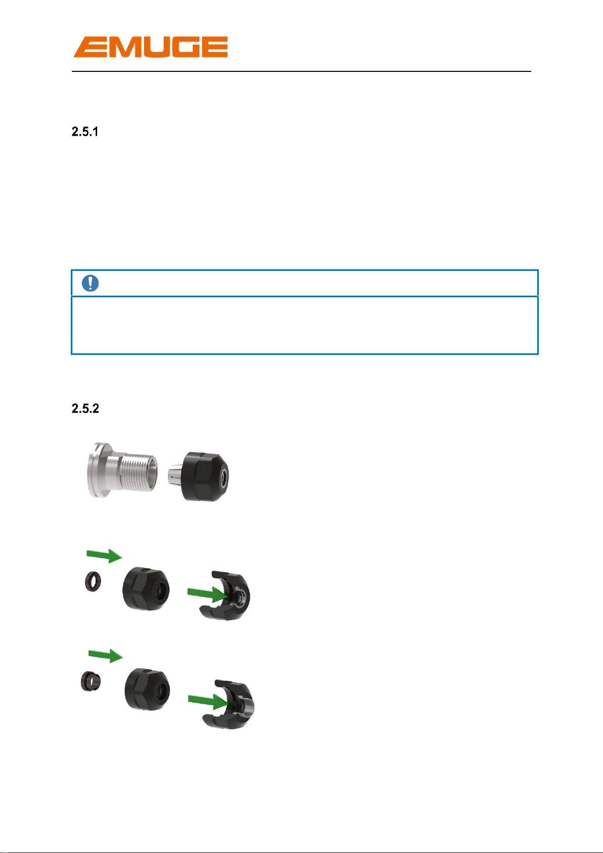
2.5 Sealing disk / cooling disk
Application
The sealing disks or cooling disks are inserted into the clamping nuts for producing
threads with internal coolant supply. The sealing disks respectively the cooling disks
additionally avoid the penetration of dirt and chips into the collet slots. We do
recommend the use of sealing disks or cooling disks.
In contrast to the sealing disks, the cooling disks guide the coolant directly along the
tool.
Note
Normally a clamping nut for sealing disks/cooling disks is part of the delivery.
The sealing disk or cooling disk hasto be ordered separately, suitable for clamping
nut and clamping diameter!
Assembly of the sealing disk or cooling disk
1. Screw off the clamping nut
2. Insert sealing disk/cooling disk
into clamping nut as shown on
picture.
Push sealing disk/cooling disk
forward into clamping nut until
you clearly hear the
engagement.
The sealing disk must be flush
at the front with the clamping
nut.
Click !
Sealing disk
Click!
Cooling disk

Speedsynchro®Mini
Operating instruction edition: 13.09.2022 15
Click!
2.6 Collets
Application
The adaptation of the tap/cold-forming tap is done via collets type ER and/or ER/GB.
With collets type ER the tap/cold forming tap is centered and clamped via the shank
diameter. With collets type ER/GB the torque - arising during the thread producing
operation - is additionally transferred via the square integrated in the collet.
Note
Due to the better torque transmission we recommend the use of collets type ER/GB.
The collet sizes for the according SpeedsynchroMini may be taken from Table 1,
page 7. The clamping diameter is specified by the tap/cold-forming tap used.
Assembly of the collet
1. Insert collet into clamping nut,
tilt collet.
The groove of the collet must
engage in the eccentric ring of the
clamping nut at the marked
position. Tilt collet in opposite
direction until it clearly engages.
→Collet is flush with clamping nut
and/or sealing disk.
1. Screw clamping nut with engaged
collet onto the thread of the collet
holder.
Groove of the collet
Eccentric ring
Marking
√

Speedsynchro®Mini
16 Operating instruction edition: 13.09.2022
2.7 Assembly of the tap/cold-forming tap
1. Insert tap/cold-forming tap
If collet and tool are provided with a
square, the tool must be turned into
position in order to be inserted into
the square of the collet!
2. Tighten clamping nut with
appropriate wrench.
Attention
In order to avoid damaging of
Speedsynchro®Mini parts, it is
necessary during the tightening
of the clamping nut via wrench
to support with open-ended
spanner .
As an alternative to the open-
ended spanner the assembly
deviceF3720900 can be used.
Note
Wrenches are part of the delivery.
To adjust the correct torque (please see table 3), we recommend to use a torque
wrench.
Table 3: Tightening torques for clamping nuts
Type
Recommended tightening
torque [Nm]
Hi-Q/ERC 11
14
Clamping nut
Data valid for the use of ER-GB collets.
The maximum tightening torque must not be
more than
25% above the recommended values.
Higher torque
may result in the damage of the collet
holder.

Speedsynchro®Mini
Operating instruction edition: 13.09.2022 17
2.8 Remove the tap/cold-forming tap, the clamping nut and the sealing disk
1. Loosen the clamping nut with
wrench
Attention
In order to avoid damaging of
Speedsynchro®Mini parts, it is
necessary during the loosening of
the clamping nut via wrench to
support with open-ended spanner
.
As an alternative to the open-
ended spanner the assembly
deviceF3720900 can be used.
2. Pull out tap/cold-forming tap
3. Screw off the clamping nut
4. Tilt collet up to the marking until it is
removed from the eccentric ring
Remove collet
5. Press the sealing disk or cooling
disk out of the clamping nut from
the front and remove it

Speedsynchro®Mini
18 Operating instruction edition: 13.09.2022
Picture 6
3 Readout operating data via NFC interface
The operating data is recorded and stored by the electronics integrated in the
SpeedsynchroMini. The readout of data is done via an NFC-enabled smartphone.
The required app can be downloaded free of charge for iOS from Apple store or for
Android operating systems from Google Play Store.
3.1 Speedsynchro- Electronics
The electronics of the Speedsynchrosystem are embedded and protected under the
cover, the NFC readout antenna is integrated inside. Depending on the operating
condition the electronics are in active or in energy saving mode.
Power is supplied by a battery integrated in the SpeedsynchroMini, the battery
charge state can be read via NFC. The battery has a service life of several years and
is replaceable. The operating data is not lost when the battery is changed.
3.2 Readout operating data
The operating data is read out via wireless coupling of smartphone and
SpeedsynchroMini antenna. The antenna is located under the cover. The position of
the antenna in the smartphone depends on manufacturer and model.
For coupling and reading the operating data, it is sufficient to move the back of the
smartphone in direct contact or within a few millimeters over the cover.
Depending on the smartphone model, the EMUGE app opens automatically and the
operating data can be read. If the app does not open automatically, it must be opened
manually before coupling the devices.

Speedsynchro®Mini
Operating instruction edition: 13.09.2022 19
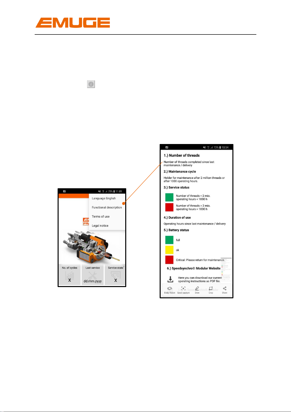
3.3 Display in the app
7 + 8 Date / Time
Shows the current date and time of time
zone Europe / Berlin.
Shows the number of threads produced since the
last maintenance or for new devices from date of
delivery. The display/number is reset to „0“during
maintenance at EMUGE.
4 Duration of use
Shows the operating hours since the last
maintenance or for new devices from date of
delivery. Is reset to „0“during maintenance at
EMUGE.
2 Last service
Shows the date of last maintenance or for new
devices the date of delivery.
3 Service status
Maintenance is recommended after production of
2 million threads or 1000 hours of operation.
If maintenance is due, the traffic indicator jumps
from green to red, which means in detail:
Number of threads < 2 Mio.
Operation hours < 1000
Number of threads > 2 Mio.
Operation hours > 1000
1
2
4
5
7
8
9
3
6
6 Battery status
The traffic light colours indicate the
status of the battery.
Specific meaning of the colours:
Fully charged
OK
Critical: Please return for
maintenance
5 Temperature
Shows the maximum temperature the
SpeedsynchroMini reached since last
maintenance/ / new delivery.
9 Device number
Shows the unique device number in addition to
the article number, is assigned by EMUGE
upon delivery.
1 Number of threads
Picture 7
Speedsynchro®Mini
20 Operating instruction edition: 13.09.2022
A short summary of the display functions is shown in the menu selection at the top
right under the item “Function description”
Tapping the button in fields 3 + 6 (picture 7, page 19) also takes you to this
page.
There are also the terms of use and the imprint.
Picture 8
Table of contents
Other EMUGE Industrial Equipment manuals


