manuals.online logo
Brands
  1. Home
  2. •
  3. Brands
  4. •
  5. Graco
  6. •
  7. Paint Sprayer
  8. •
  9. Graco 205-627 Operation manual

Graco 205-627 Operation manual

This manual suits for next models

1

Other Graco Paint Sprayer manuals

Graco 308-328 Operation manual

Graco

Graco 308-328 Operation manual

Graco ULTRA MAX II 1095 User manual

Graco

Graco ULTRA MAX II 1095 User manual

Graco SUPER NOVA SP User manual

Graco

Graco SUPER NOVA SP User manual

Graco 308972R Operation manual

Graco

Graco 308972R Operation manual

Graco XHF Parts list manual

Graco

Graco XHF Parts list manual

Graco 222973 Operation manual

Graco

Graco 222973 Operation manual

Graco Ultra Guide

Graco

Graco Ultra Guide

Graco 255963 Parts list manual

Graco

Graco 255963 Parts list manual

Graco 805-074 Series A User manual

Graco

Graco 805-074 Series A User manual

Graco GM5000HD User manual

Graco

Graco GM5000HD User manual

Graco EH 333 HYDRA-SPRAY A Series Operation manual

Graco

Graco EH 333 HYDRA-SPRAY A Series Operation manual

Graco LineDriver Use and care manual

Graco

Graco LineDriver Use and care manual

Graco 278675 Instruction Manual

Graco

Graco 278675 Instruction Manual

Graco RTX 1500 Use and care manual

Graco

Graco RTX 1500 Use and care manual

Graco MERKUR 309463N Operation manual

Graco

Graco MERKUR 309463N Operation manual

Graco GMAX 3400 Instruction Manual

Graco

Graco GMAX 3400 Instruction Manual

Graco GTX 257030 User manual

Graco

Graco GTX 257030 User manual

Graco Ultimate NOVA 395 PC Guide

Graco

Graco Ultimate NOVA 395 PC Guide

Graco Reactor 2 E-30 Use and care manual

Graco

Graco Reactor 2 E-30 Use and care manual

Graco ti2652a User manual

Graco

Graco ti2652a User manual

Graco 243011 User manual

Graco

Graco 243011 User manual

Graco C Series Operation manual

Graco

Graco C Series Operation manual

Graco ULTRA MARK X Manual

Graco

Graco ULTRA MARK X Manual

Graco HYDRA-SPRAY EH 333 226-333 Operation manual

Graco

Graco HYDRA-SPRAY EH 333 226-333 Operation manual

Popular Paint Sprayer manuals by other brands

Idex Akron Brass FS100 quick start guide

Idex

Idex Akron Brass FS100 quick start guide

mbp TEL 15BS instructions

mbp

mbp TEL 15BS instructions

Solo 425 Classic Original instructions

Solo

Solo 425 Classic Original instructions

WAGNER AirCoat GM 4100 AC operating manual

WAGNER

WAGNER AirCoat GM 4100 AC operating manual

Titan MultiFinish 440 owner's manual

Titan

Titan MultiFinish 440 owner's manual

SNOWJOE Sunjoe 24V-GS-LTW-RM Operator's manual

SNOWJOE

SNOWJOE Sunjoe 24V-GS-LTW-RM Operator's manual

Walther FSP-01 Assembly instructions

Walther

Walther FSP-01 Assembly instructions

Fimco LG-4-3-1 owner's manual

Fimco

Fimco LG-4-3-1 owner's manual

Nordson MicroMax 2 manual

Nordson

Nordson MicroMax 2 manual

Bonide 051 Operation and service instructions

Bonide

Bonide 051 Operation and service instructions

zogics Z-DAS instruction manual

zogics

zogics Z-DAS instruction manual

KISANKRAFT KK-KBS-165 Operation manual

KISANKRAFT

KISANKRAFT KK-KBS-165 Operation manual

Matrix SG 650 Translation of the original instructions

Matrix

Matrix SG 650 Translation of the original instructions

paasche VV Instructions and parts list

paasche

paasche VV Instructions and parts list

Carlisle DeVilbiss JGA-510 Service manual

Carlisle

Carlisle DeVilbiss JGA-510 Service manual

Gardena 11120 Operator's manual

Gardena

Gardena 11120 Operator's manual

DeVilbiss LUNA2i Operation manual

DeVilbiss

DeVilbiss LUNA2i Operation manual

WAGNER W 125 manual

WAGNER

WAGNER W 125 manual

manuals.online logo
manuals.online logoBrands
  • About & Mission
  • Contact us
  • Privacy Policy
  • Terms and Conditions

Copyright 2025 Manuals.Online. All Rights Reserved.

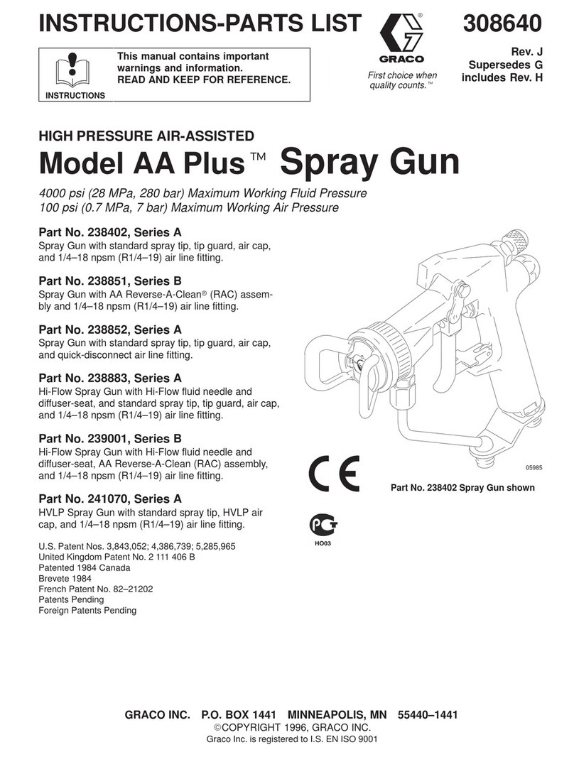
306–726
Rev. R
Supersedes P
First choice when
quality counts.t
INSTRUCTIONS-PARTS LIST
INSTRUCTIONS
This manual contains important
warnings and information.
READ AND KEEP FOR REFERENCE.
Model 205–627, Series H
Pail length, for 5 or 10 gallons,
with Relax-A-Valve.
Model 205–628, Series H
Drum length for open-head drum,
with Relax-A-Valve
06698
Model 205–627 Shown
President 10:1 Ratio
Air Spray System
FOR NON-ABRASIVE FLUIDS
1800 psi (126 bar, 12.6 MPa) Maximum Working Pressure
GRACO INC. P.O. BOX 1441 MINNEAPOLIS, MN 55440–1441
ECOPYRIGHT 1996, GRACO INC.
Graco Inc. is registered to I.S. EN ISO 9001
Parts
2 306-726
Table of Contents
Warnings 2. . . . . . . . . . . . . . . . . . . . . . . . . . . . . . . . . . . . . .
Installation 5. . . . . . . . . . . . . . . . . . . . . . . . . . . . . . . . . . . . .
Operation 8. . . . . . . . . . . . . . . . . . . . . . . . . . . . . . . . . . . . .
Maintenance 10. . . . . . . . . . . . . . . . . . . . . . . . . . . . . . . . . .
Troubleshooting 11. . . . . . . . . . . . . . . . . . . . . . . . . . . . . . .
Displacement Pump Repair 12. . . . . . . . . . . . . . . . . . . . .
Check Valve Adjustment 12. . . . . . . . . . . . . . . . . . . . . . .
Relax-A-Valve Repair 13. . . . . . . . . . . . . . . . . . . . . . . . . .
Parts Lists and Drawings
Model 205–628 14. . . . . . . . . . . . . . . . . . . . . . . . . . . . .
Model 205–627 15. . . . . . . . . . . . . . . . . . . . . . . . . . . . .
Relax-A-Valve 16. . . . . . . . . . . . . . . . . . . . . . . . . . . . . .
Technical Data 16. . . . . . . . . . . . . . . . . . . . . . . . . . . . . . . .
Dimensions 17. . . . . . . . . . . . . . . . . . . . . . . . . . . . . . . . . . .
Warranty 20. . . . . . . . . . . . . . . . . . . . . . . . . . . . . . . . . . . . .
Graco Phone Numbers 20. . . . . . . . . . . . . . . . . . . . . . . . .
Symbols
Warning Symbol
WARNING
This symbol alerts you to the possibility of serious
injury or death if you do not follow the instructions.
Caution Symbol
CAUTION
This symbol alerts you to the possibility of damage to
or destruction of equipment if you do not follow the
instructions.
WARNING
EQUIPMENT MISUSE HAZARD
Equipment misuse can cause the equipment to rupture or malfunction and result in serious injury.
DThis equipment is for professional use only.
DRead all instruction manuals, tags, and labels before operating the equipment.
DUse the equipment only for its intended purpose. If you are not sure, call your Graco distributor.
DDo not alter or modify this equipment.
DCheck equipment daily. Repair or replace worn or damaged parts immediately.
DDo not exceed the maximum working pressure stated on the equipment or in the Technical Data
for your equipment. Do not exceed the maximum working pressure of the lowest rated component
in your system.
DUse fluids and solvents which are compatible with the equipment wetted parts. Refer to the Tech-
nical Data section of all equipment manuals. Read the fluid and solvent manufacturer’s warnings.
DHandle hoses carefully. Do not pull on hoses to move equipment.
DRoute hoses away from traffic areas, sharp edges, moving parts, and hot surfaces. Do not expose
Graco hoses to temperatures above 66_C (150_F) or below –40_C (–40_F).
DWear hearing protection when operating this equipment.
DDo not move or lift pressurized equipment.
DComply with all applicable local, state, and national fire, electrical, and safety regulations.
3306-726
WARNING
INJECTION HAZARD
Spray from the gun, leaks or ruptured components can inject fluid into your body and cause extremely
serious injury, including the need for amputation. Fluid splashed in the eyes or on the skin can also
cause serious injury.
DFluid injected into the skin is a serious injury. The injury may look like just a cut, but it is a serious
injury. Get immediate medical attention.
DDo not point the gun at anyone or at any part of the body.
DDo not put your hand or fingers over the spray tip.
DDo not stop or deflect leaks with your hand, body, glove or rag.
DDo not “blow back”fluid; this is not an air spray system.
DAlways have the tip guard and the trigger guard on the gun when spraying.
DCheck the gun diffuser operation weekly. Refer to the gun manual.
DBe sure the gun trigger safety operates before spraying.
DLock the gun trigger safety when you stop spraying.
DFollow the Pressure Relief Procedure on page 8 if the spray tip clogs and before cleaning,
checking or servicing the equipment.
DTighten all fluid connections before operating the equipment.
DCheck the hoses, tubes, and couplings daily. Replace worn, damaged, or loose parts immediately.
Permanently coupled hoses cannot be repaired; replace the entire hose.
MOVING PARTS HAZARD
Moving parts can pinch or amputate your fingers.
DKeep clear of all moving parts when starting or operating the pump.
DBefore checking or servicing the equipment, follow the Pressure Relief Procedure on page 8 to
prevent the equipment from starting unexpectedly.
4 306-726
WARNING
FIRE AND EXPLOSION HAZARD
Improper grounding, poor ventilation, open flames or sparks can cause a hazardous condition and re-
sult in a fire or explosion and serious injury.
DGround the equipment and the object being sprayed. Refer to Grounding on page 5.
DIf there is any static sparking or you feel an electric shock while using this equipment, stop spray-
ing immediately. Do not use the equipment until you identify and correct the problem.
DProvide fresh air ventilation to avoid the buildup of flammable fumes from solvents or the fluid
being sprayed.
DKeep the spray area free of debris, including solvent, rags, and gasoline.
DBefore operating this equipment, electrically disconnect all equipment in the spray area.
DBefore operating this equipment, extinguish all open flames or pilot lights in the spray area.
DDo not smoke in the spray area.
DDo not turn on or off any light switch in the spray area while spraying or while operating if fumes
are present.
DDo not operate a gasoline engine in the spray area.
DNever use 1,1,1–trichloroethane, methylene chloride, other halogenated hydrocarbon solvents, or
fluids containing such solvents in this equipment. Such use could result in a serious chemical
reaction, with the possibility of explosion, which could cause death, serious injury, and/or substan-
tial property damage.
Consult your fluid suppliers to ensure that fluids being used are compatible with aluminum and zinc
parts.
TOXIC FLUID HAZARD
Hazardous fluid or toxic fumes can cause serious injury or death if splashed in the eyes or on the skin,
inhaled, or swallowed.
DKnow the specific hazards of the fluid you are using.
DStore hazardous fluid in an approved container. Dispose of hazardous fluid according to all local,
state and national guidelines.
DAlways wear protective eyewear, gloves, clothing and respirator as recommended by the fluid and
solvent manufacturer.
5306-726
Installation
General Information
NOTE: Reference numbers and letters in parentheses
refer to callouts in the Figs. and parts drawing.
NOTE: Always use Genuine Graco Parts and Acces-
sories, available from your Graco distributor.
Grounding
WARNING
FIRE AND EXPLOSION HAZARD
Before operating the pump, ground the
system as explained below. Also read
the section FIRE OR EXPLOSION HAZ-
ARD on page 4.
1. Pump: use a ground wire and clamp as shown in
Fig. 1. Loosen the grounding lug locknut (W) and
washer (X). Insert one end of a 12 ga (1.5 mm@)
minimum ground wire (Y) into the slot in lug (Z)
and tighten the locknut securely. Connect the other
end of the wire to a true earth ground. Order part
number 222–011 Grounding Clamp and Wire.
2. Air and fluid hoses: use only conductive hoses.
3. Air compressor: follow manufacturer’s recommen-
dations.
4. Spray gun or dispensing valve: ground through
connection to a grounded fluid hose and pump.
5. Fluid supply container: follow your local code.
6. Object being sprayed: follow your local code.
7. Solvent pails used when flushing: follow your local
code. Use only conductive metal pails, placed on a
grounded surface. Do not place the pail on a
nonconductive surface, such as paper or card-
board, which interrupts the grounding continuity.
8. To maintain grounding continuity when flushing or
relieving pressure, hold a metal part of the spray
gun firmly to the side of a grounded metal pail,
then trigger the gun.
0720
Fig. 1
Y
W
ZX
6 306-726
Installation
NOTE: Reference numbers and letters in parentheses
in the text refer to callouts in the figure illustrations and
the parts drawing.
The Typical installation shown on page 7 is only a
guide to electing and installing required and optional
accessories. For assistance in designing a system to
suit your needs, contact your Graco representative.
Mount the pump to suit the type of installation planned.
The pump dimensions and mounting hole layout are
shown on page 17.
Pail and Drum Length Pumps
Install the pump in the drum or pail, using a suitable
cover, bung adapter, or mounting clamp. The pump
must be 1/2 in. (13 mm) off the bottom of the pail or
drum.
If the pump has a drain back tube, connect a drain
hose to it and route the hose back to the supply con-
tainer.
NOTE: In a closed-head drum, be sure to loosen the
vent plug in the drum cover to prevent formation of a
vacuum.
WARNING
Two accessories are required in your system: a
bleed-type master air valve (A), if your pump does
not have a Relax-A-Valve, and a fluid drain valve
(H). These accessories help reduce the risk of
serious injury including injection, splashing in the
eyes, and injury from moving parts if you are
adjusting or repairing the pump.
The bleed-type master air valve relieves air trapped
between this valve and the pump after the air
regulator is shut off. Trapped air can cause the
pump to cycle unexpectedly. Locate the valve close
to the pump.
The fluid drain valve assists in relieving fluid pres-
sure in the displacement pump, hose, and gun;
triggering the gun to relieve pressure may not be
sufficient.
Pumps With Relax-A-Valve
An Evenflo air regulator may be installed on pumps
having a Relax-A-Valve. This regulator prevents initial
surging of non-atomized fluid when the gun is trig-
gered. Air pressure in the pump is relieved automati-
cally each time the gun trigger is released. When used
with a Relax-A-Valve set in the automatic position, fluid
pressure is relieved automatically also.
7306-726
Installation
All Pumps
Install the air line accessories in the approximate order
shown in the Typical Installation drawing. A pump
runaway valve (B) senses when the pump is running
too fast and shuts off the air supply to the motor. For
automatic air motor lubrication, install an air line lubri-
cator (D). (For manual lubrication, see Maintenance on
page 10). Install the bleed-type master air valve (A)
within easy reach of the pump. Install an air regulator
(E) to control air to the motor and pump speed. An air
line filter (C) removes harmful dirt and moisture from
your compressed air supply.
Be sure that the air supply hose is properly grounded,
and is at least 1.2 in. (13 mm) ID in order to supply an
adequate volume of air to the motor.
On the fluid line, install a drain valve (H) close to the
fluid outlet to assist in relieving fluid pressure (not
required in pumps having a Relax-A-Valve). Connect a
suitable grounded fluid hose and spray gun or dispens-
ing valve to the pump’s 3/4 in. npt outlet.
Typical Installation
06706
KEY
A
B
C
D
E
H
J
K
L
20,
21
Bleed-Type Master Air Valve
Pump Runaway Valve
Air Line Filter
Air Line Lubricator
Pump Air Regulator
Drain Valve
Pump Ground Wire
Grounded Fluid Hose
Grounded Air Hose
Relax-A-Valve
Drain Back Tube
1/2”Minimum
A
L
CA20
21
EDB
J
HK
8 306-726
Operation
Pressure Relief Procedure
With the Evenflo control, its bypass valve, and the
pump Relax-A-Valve properly set, fluid pressure is
relieved from the pump and hose each time you re-
lease the gun trigger. Always engage the gun trigger
safety when you stop spraying. To relieve air pressure,
close the Evenflo regulators and open the bleed-type
master air valve.
WARNING
INJECTION HAZARD
If you suspect that the Evenflo system is
not properly set, or that pressure is not
fully relieved, the system pressure must
be manually relieved to prevent the system from
starting or spraying accidentally. Fluid under high
pressure can be injected through the skin and
cause serious injury. To reduce the risk of an injury
from injection, splashing fluid, or moving parts, fol-
low the Pressure Relief Procedure whenever you:
Dare instructed to relieve the pressure,
Dstop spraying,
Dcheck or service any of the system equipment,
Dor install or clean the spray tips.
1. Engage the spray gun or dispensing valve safety
latch.
2. Close the pump air regulator.
3. Close the master bleed-type air valve (required).
4. Disengage the gun or dispensing valve safety
latch.
5. Hold a metal part of the gun/valve firmly to a
grounded metal waste container and trigger to
relieve fluid pressure.
6. Engage the safety latch again.
7. Open the pump drain valve (required in your
system), having a container to catch the drainage.
NOTE: If your pump has a Relax-A-Valve set in the
automatic position, step 7 is not necessary.
8. Leave the drain valve open until you are ready to
spray again.
If you suspect that the spray tip or hose is completely
clogged, or that pressure has not been fully relieved
after following the steps above, very slowly loosen the
tip guard retaining nut or hose end coupling and relieve
pressure gradually, then loosen completely. Now clear
the tip or hose.
WARNING
Never operate the pump with the air motor plate
removed. Moving parts in the piston can pinch or
amputate fingers.
Startup
WARNING
To reduce the risk of serious injury whenever you
are instructed to relieve pressure, always follow the
Pressure Relief Procedure on page 8.
The pump was tested in oil, and some oil was left in
the pump to protect it from corrosion. if the oil will
contaminate the fluid your are pumping, flush it out.
To start the pump, close the fluid drain valve (H). Open
the bleed-type master air valves (A). Holding a metal
part of the spray gun/dispensing valve firmly against
the side of a grounded metal pail, hold the trigger open
while slowly opening the air regulator (E), Run the
pump slowly until all air is purged from the gun/valve.
Release the trigger and engage the safety latch (if
applicable).
Use the air regulator (E) to control fluid pressure and
pump speed. Always use the lowest pressure neces-
sary to get the desired results. Higher pressures cause
premature pump wear and spray tip wear, and usually
do not improve the spray pattern.
WARNING
To reduce the risk of overpressurizing your system,
which could result in component rupture and cause
serious injury, never exceed the maximum working
pressure of the lowest rated component in your
system. Lowering the air pressure to the motor will
proportionately lower the fluid outlet pressure from
the pump. Refer to the Technical Data on page 16
for the maximum air and fluid working pressure of
this pump.
9306-726
Operation
Using the Relax-A-Valve
If your pump has a Relax-A-Valve, it can be used to
mix fluid by circulation (except in inductor-type follow
plate installations), and it can be set to relieve fluid line
pressure each time the pump air pressure is relieved.
To circulate fluid, open the Relax-A-Valve by loosening
the locknut (119) and turning the T-handle screw (110)
counterclockwise as far as possible. Start the pump
and circulate the fluid as necessary. Stop the pump
and close the Relax-A-Valve or set it in the automatic
position. See Fig. 2.
To set the automatic position, loosen the locknut (119)
and turn the T-handle screw (110) clockwise as far as
possible. Back off the T-handle screw four turns and
tighten the locknut. During normal operation, the fluid
pressure is relieved automatically each time the air
pressure to the pump is relieved.
NOTE: If your installation includes an Evenflo pressure
regulator, air to the pump is automatically relieved
each time your close the gun trigger, and the Relax--A-
Valve, in turn, relieves fluid pressure.
Without an Evenflo, the bleed-type master air valve (A)
should be used to relieve pump air pressure.
Fig. 2 06698
119
110
In a direct supply system, with adequate air pressure
supplied to the motor, the pump starts when the gun or
dispensing valve is opened, and stalls against pres-
sure when it is closed.
If the pump accelerates quickly or is running too fast,
stop it immediately. Check the fluid supply and refill it if
necessary. Prime the pump to remove all air from the
system, or flush the pump, relieve the pressure, but
leave the system filled with mineral spirits or an oil-
based solvent to protect the pump from corrosion.
NOTE: A pump runaway valve (B) can be installed on
the air line to automatically shut off the pump if it starts
to run too fast.
Shutdown and Care of the Pump
WARNING
To reduce the risk of serious injury whenever you
are instructed to relieve pressure, always follow the
Pressure Relief Procedure on page 8.
Relieve the pressure whenever you stop spraying.
Always stop the pump at the bottom of its stroke to
prevent fluid from drying on the rod and damaging the
throat packings.
If you are pumping fluid which dries, hardens, or sets
up, flush the system with a compatible solvent as often
as necessary to prevent a build up of dried fluid in the
pump or hoses.
10 306-726
Maintenance
Lubrication
If your system includes an automatic air line lubricator,
adjust the lubricator as instructed in the separate
instruction manual.
For manual lubrication, each day, remove the air inlet
hose and place 12 to 15 drops of high quality, light
motor oil in the inlet. Reattach the hose and turn on the
air to blow the oil into the motor.
Throat Packing Adjustment
WARNING
To reduce the risk of serious injury whenever you
are instructed to relieve pressure, always follow the
Pressure Relief Procedure on page 8.
Once a week, or after each 40 hours of operation,
check the tightness of the throat packing nut. It should
be tight enough to stop leakage, but no tighter.
To check, first relieve the pressure. Then, remove the
identification plate (M) from the motor. Using a spanner
wrench or a 0.22 in (5.6 mm) diameter rod, adjust the
nut. Reinstall the identification plate before operating
the pump. See Fig. 3.
Flushing
WARNING
To reduce the risk of serious injury whenever you
are instructed to relieve pressure, always follow the
Pressure Relief Procedure on page 8.
To reduce the risk of injection injury, static sparking, or
splashing in the eyes or on the skin, relieve the pres-
sure. Then, remove the spray tip (spray guns or spray
valves only) before flushing. Hold a metal part of the
gun/valve firmly to the side of a grounded metal pail
and use the lowest possible fluid pressure during
flushing.
Fig. 3
06701
MPacking
Nut
Leather
Throat
Packings
Corrosion Protection
WARNING
To reduce the risk of serious injury whenever you
are instructed to relieve pressure, always follow the
Pressure Relief Procedure on page 8.
CAUTION
Water, or even moist air, can cause your pump to
corrode. To help prevent corrosion, never leave the
pump filled with water-based fluid or air. After normal
flushing, flush the pump again with mineral spirits or
oil-based solvent, and relieve the pressure. This
leaves the mineral spirits in the pump.