manuals.online logo
Brands
  1. Home
  2. •
  3. Brands
  4. •
  5. Graco
  6. •
  7. Paint Sprayer
  8. •
  9. Graco Series A Operation manual

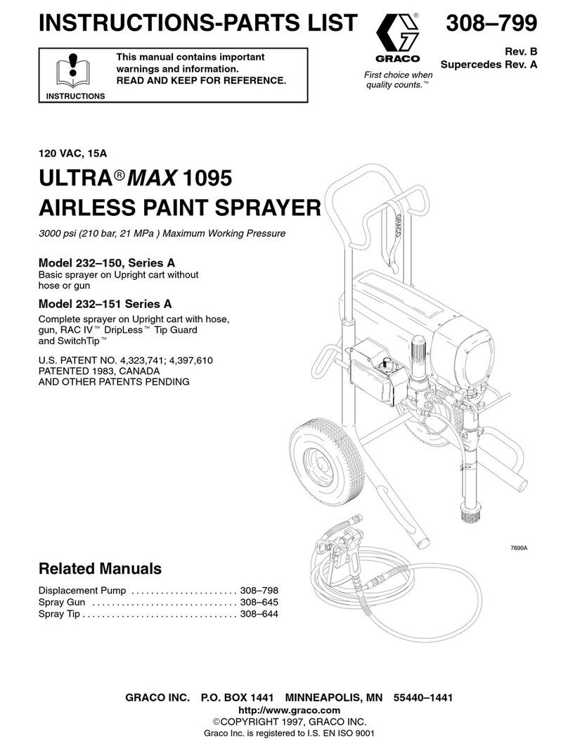
Graco Series A Operation manual

Other manuals for Series A

66

This manual suits for next models

1

Other Graco Paint Sprayer manuals

Graco Pro Xp H60T10 User manual

Graco

Graco Pro Xp H60T10 User manual

Graco XM Series User manual

Graco

Graco XM Series User manual

Graco 2300 Hi-Boy Guide

Graco

Graco 2300 Hi-Boy Guide

Graco 3A0243A Operating instructions

Graco

Graco 3A0243A Operating instructions

Graco 310624E User manual

Graco

Graco 310624E User manual

Graco RTX2500 Guide

Graco

Graco RTX2500 Guide

Graco NOVA 390 PC Guide

Graco

Graco NOVA 390 PC Guide

Graco 222300 Operation manual

Graco

Graco 222300 Operation manual

Graco LINE LAZER GM 5000 Series Operation manual

Graco

Graco LINE LAZER GM 5000 Series Operation manual

Graco 805-074 Series A User manual

Graco

Graco 805-074 Series A User manual

Graco IronMax V Operating instructions

Graco

Graco IronMax V Operating instructions

Graco 309489 User manual

Graco

Graco 309489 User manual

Graco EM 380 User manual

Graco

Graco EM 380 User manual

Graco 25R268 Guide

Graco

Graco 25R268 Guide

Graco SDX Operating instructions

Graco

Graco SDX Operating instructions

Graco AirPro 312579 User manual

Graco

Graco AirPro 312579 User manual

Graco 16N661 Use and care manual

Graco

Graco 16N661 Use and care manual

Graco 16N664 Use and care manual

Graco

Graco 16N664 Use and care manual

Graco Pro Xp L40T10 Parts list manual

Graco

Graco Pro Xp L40T10 Parts list manual

Graco GM 3500 Datasheet

Graco

Graco GM 3500 Datasheet

Graco HVLP EDGE Gun 256855 Operating instructions

Graco

Graco HVLP EDGE Gun 256855 Operating instructions

Graco Contractor 288477 Operation manual

Graco

Graco Contractor 288477 Operation manual

Graco FinishPro 256845 User manual

Graco

Graco FinishPro 256845 User manual

Graco 918316 Operation manual

Graco

Graco 918316 Operation manual

Popular Paint Sprayer manuals by other brands

Idex Akron Brass FS100 quick start guide

Idex

Idex Akron Brass FS100 quick start guide

mbp TEL 15BS instructions

mbp

mbp TEL 15BS instructions

Solo 425 Classic Original instructions

Solo

Solo 425 Classic Original instructions

WAGNER AirCoat GM 4100 AC operating manual

WAGNER

WAGNER AirCoat GM 4100 AC operating manual

Titan MultiFinish 440 owner's manual

Titan

Titan MultiFinish 440 owner's manual

SNOWJOE Sunjoe 24V-GS-LTW-RM Operator's manual

SNOWJOE

SNOWJOE Sunjoe 24V-GS-LTW-RM Operator's manual

Walther FSP-01 Assembly instructions

Walther

Walther FSP-01 Assembly instructions

Fimco LG-4-3-1 owner's manual

Fimco

Fimco LG-4-3-1 owner's manual

Nordson MicroMax 2 manual

Nordson

Nordson MicroMax 2 manual

Bonide 051 Operation and service instructions

Bonide

Bonide 051 Operation and service instructions

zogics Z-DAS instruction manual

zogics

zogics Z-DAS instruction manual

KISANKRAFT KK-KBS-165 Operation manual

KISANKRAFT

KISANKRAFT KK-KBS-165 Operation manual

Matrix SG 650 Translation of the original instructions

Matrix

Matrix SG 650 Translation of the original instructions

paasche VV Instructions and parts list

paasche

paasche VV Instructions and parts list

Carlisle DeVilbiss JGA-510 Service manual

Carlisle

Carlisle DeVilbiss JGA-510 Service manual

Gardena 11120 Operator's manual

Gardena

Gardena 11120 Operator's manual

DeVilbiss LUNA2i Operation manual

DeVilbiss

DeVilbiss LUNA2i Operation manual

WAGNER W 125 manual

WAGNER

WAGNER W 125 manual

manuals.online logo
manuals.online logoBrands
  • About & Mission
  • Contact us
  • Privacy Policy
  • Terms and Conditions

Copyright 2025 Manuals.Online. All Rights Reserved.

Instructions – Parts List
GRACO INC. P.O. BOX 1441 MINNEAPOLIS, MN 55440–1441
Copyright 1996, Graco Inc. is registered to I.S. EN ISO 9001
STAINLESS STEEL, AIR–OPERATED
Paint Spray Gun
3000 psi (21 MPa, 210 bar) Maximum Working Pressure
Model 238377, Series A
308613D
Important Safety Instructions
Read all warnings and instructions in this manual.
Save these instructions.
05952
A
Parts
3
308613
Table of Contents
Warnings 3. . . . . . . . . . . . . . . . . . . . . . . . . . . . . . . . . . . . . .
Installation 6. . . . . . . . . . . . . . . . . . . . . . . . . . . . . . . . . . . . .
Operation 7. . . . . . . . . . . . . . . . . . . . . . . . . . . . . . . . . . . . .
Maintenance 8. . . . . . . . . . . . . . . . . . . . . . . . . . . . . . . . . . .
Service 8. . . . . . . . . . . . . . . . . . . . . . . . . . . . . . . . . . . . . . .
Troubleshooting Chart 9. . . . . . . . . . . . . . . . . . . . . . . . . .
Parts 11. . . . . . . . . . . . . . . . . . . . . . . . . . . . . . . . . . . . . . . .
Technical Data 12. . . . . . . . . . . . . . . . . . . . . . . . . . . . . . . .
Graco Warranty 14. . . . . . . . . . . . . . . . . . . . . . . . . . . . . . .
Graco Information 14. . . . . . . . . . . . . . . . . . . . . . . . . . . . .
Symbols
Warning Symbol
WARNING
This symbol alerts you to the possibility of serious
injury or death if you do not follow the instructions.
Caution Symbol
CAUTION
This symbol alerts you to the possibility of damage to
or destruction of equipment if you do not follow the
instructions.
WARNING
FIRE AND EXPLOSION HAZARD
Improper grounding, poor ventilation, open flames or sparks can cause a hazardous condition and re-
sult in a fire or explosion and serious injury.
DIf there is any static sparking or you feel an electric shock while using this equipment, stop spray-
ing immediately. Do not use the equipment until you identify and correct the problem.
DProvide fresh air ventilation to avoid the buildup of flammable fumes from solvents or the fluid be-
ing sprayed.
DKeep the spray area free of debris, including solvent, rags, and gasoline.
DElectrically disconnect all equipment in the spray area.
DExtinguish all open flames or pilot lights in the spray area.
DDo not smoke in the spray area.
DDo not turn on or off any light switch in the spray area while operating or if fumes are present.
DDo not operate a gasoline engine in the spray area.
DGround the equipment and the object being sprayed. See Grounding on page 6.
4 308613
WARNING
INJECTION HAZARD
Spray from the gun, leaks or ruptured components can inject fluid into your body and cause extremely
serious injury, including the need for amputation. Fluid splashed in the eyes or on the skin can also
cause serious injury.
DFluid injected into the skin is a serious injury. The injury may look like just a cut, but it is a serious
injury. Get immediate surgical treatment.
DDo not point the gun at anyone or at any part of the body.
DDo not put your hand or fingers over the spray tip.
DDo not stop or deflect leaks with your hand, body, glove or rag.
DDo not “blow back” fluid; this is not an air spray system.
DAlways have the tip guard and the trigger guard on the gun when spraying.
DCheck the gun diffuser operation weekly. Refer to the gun manual.
DBe sure the gun trigger safety operates before spraying.
DLock the gun trigger safety when you stop spraying.
DFollow the Pressure Relief Procedure on page 7 if the spray tip clogs and before cleaning,
checking or servicing the equipment.
DTighten all fluid connections before operating the equipment.
DCheck the hoses, tubes, and couplings daily. Replace worn or damaged parts immediately. Do not
repair high pressure couplings; you must replace the entire hose.
DFluid hoses must have spring guards on both ends, to help protect them from rupture caused by
kinks or bends near the couplings. n
TOXIC FLUID HAZARD
Hazardous fluid or toxic fumes can cause serious injury or death if splashed in the eyes or on the skin,
inhaled, or swallowed.
DKnow the specific hazards of the fluid you are using.
DStore hazardous fluid in an approved container. Dispose of hazardous fluid according to all local,
state and national guidelines.
DAlways wear protective eyewear, gloves, clothing and respirator as recommended by the fluid and
solvent manufacturer.
5
308613
WARNING
INSTRUCTIONS
EQUIPMENT MISUSE HAZARD
Equipment misuse can cause the equipment to rupture or malfunction and result in serious injury.
DThis equipment is for professional use only.
DRead all instruction manuals, tags, and labels before operating the equipment.
DUse the equipment only for its intended purpose. If you are not sure, call your distributor.
DDo not alter or modify this equipment.
DCheck equipment daily. Repair or replace worn or damaged parts immediately.
DDo not exceed the maximum working pressure of the lowest rated system component. Refer to the
Technical Data on page 12 for the maximum working pressure of this equipment.
DUse fluids and solvents which are compatible with the equipment wetted parts. Refer to the Tech-
nical Data section of all equipment manuals. Read the fluid and solvent manufacturer’s warnings.
DDo not use 1,1,1–trichloroethane, methylene chloride, other halogenated hydrocarbon solvents or
fluids containing such solvents in pressurized aluminum equipment. Such use could result in a
chemical reaction, with the possibility of explosion.
DDo not use hoses to pull equipment.
DRoute hoses away from traffic areas, sharp edges, moving parts, and hot surfaces. Do not expose
Graco hoses to temperatures above 82_C (180_F) or below –40_C (–40_F).
DDo not lift pressurized equipment.
DComply with all applicable local, state, and national fire, electrical, and safety regulations.
DWear ear protection when operating this equipment.
6 308613
Installation
NOTE: Reference numbers and letters in parentheses
in the text refer to the callouts in Figures 1, 2, and 3,
and the Parts Drawings.
Accessories are available from Graco. Be sure all
accessories are properly sized to withstand the pres-
sures in the system.
Mount Valve
Mount the valve on a 0.50 in. (12.7 mm) diameter rod
on a mounting fixture or a dispensing machine. The
paint gun has a clamping set screw (6) for mounting.
Connect the Air Lines
Clean all lines and connections of dirt, burrs, etc. and
blow them out with clean air before connecting them to
the system. Install an air filter in the air supply line to
remove harmful dirt and moisture from the compressed
air.
Connect the Fluid Lines
Connect a grounded fluid line from the pump to the
fluid inlet adapter of the paint spray gun. You should
install a fluid pressure regulator to control fluid pres-
sure to the paint spray gun. A regulator enables you to
control fluid pressure more accurately than by regulat-
ing hydraulic pressure to the pump.
Install a fluid filter to remove particles and sediment
which may clog the tip.
Flush the System
Before flushing, always follow the Pressure Relief
Procedure on page 7. Start the pump and flush the
system with a compatible solvent as explained in the
instructions for your pump. Check the system under
pressure for leaks; if any are found, follow the Pres-
sure Relief Procedure on page 7 and repair the
leaks. Pressurize the system again and make sure the
leaking has stopped.
Grounding
Proper grounding is essential to maintaining a safe
system.
To reduce the risk of static sparking, ground the pump,
paint spray gun and all other system equipment.
1. Pump: use a ground wire and clamp.
2. Air compressors and hydraulic power supplies:
follow manufacturer’s recommendations.
3. Air and fluid hoses connected to the pump: use
only grounded hoses with a maximum of 500 feet
(150 m) combined hose length to ensure ground-
ing continuity.
4. Dispensing valve: obtain grounding through con-
nection to a properly grounded fluid hose and
pump.
5. Fluid supply container: according to local code.
6. All solvent pails used when flushing: ground ac-
cording to local code. Use only metal pails, which
are conductive. Do not place the pail on a non-
conductive surface, such as paper or cardboard,
which interrupts the grounding continuity.
7
308613
Operation
Adjustments
Before each day’s operation, lubricate with a spray of
oil inside the protection tube (13) to prevent fluid
buildup on these parts. Any buildup could damage the
valve packings (16, 17 or 18).
Set the actuating air to at least 50 psi (3.5 bar) and
start the pump. Adjust the pump speed and pressure
to obtain the desired flow rate. Always use the lowest
pump speed necessary to get the results you want.
Pressure Relief Procedure
WARNING
FLUID INJECTION HAZARD
To reduce the risk of serious bodily in-
jury, including fluid injection,splashing in
the eyes or on the skin, or injury from
moving parts, always follow this procedure when-
ever you shut off the pump, when checking or serv-
icing any part of the dispensing system, when in-
stalling, cleaning, or changing part of the valve, and
whenever you stop dispensing.
1. Shut off the power to the pump.
2. Close the bleed-type master air valve (required
with air-powered pumps).
3. Actuate the dispensing valve to relieve pressure.
4. Open the pump drain valve (required in your
system) to help relieve fluid pressure in the dis-
placement pump. Actuating the dispensing valve to
relieve pressure may not be sufficient. Have a
container ready to catch the drainage.
5. Leave the drain valve(s) open until you are ready
to dispense again.
If you suspect that the dispensing valve or hose is
completely clogged, or that pressure has not been fully
relieved after following the steps above, very slowly
loosen the hose end coupling and relieve pressure
gradually, then loosen completely. Now clear the valve
or hose.
APPLICATION DATA
APPLICATION
RECOMMENDATIONS*
TRAVEL SPEED IN MILES PER HOUR (KPH)
Based on 15 mils (.06 mm) wet paint
3
(5)
4
(6)
5
(8)
6
(10)
7
(11)
8
(12)
9
(14)
10
(16)
11
(18)
12
(19)
Paint Tip Size
For a 4 inch (101 mm) wide line 433 433 439 439 443 443 445 449 453 457
For a 6 inch (152 mm) wide line 539 539 543 549 559 561 565
For a 12 inch (304 mm) wide line 643 649
Operating Pressure psi (bar)
Paint System 1500
(102)
1500
(102)
1500
(102)
1500
(102)
1500
(102)
1500
(102)
1500
(102)
1500
(102)
1500
(102)
1500
(102)
* Coverage may vary depending on paint used.
8 308613
Maintenance
Clean Dispensing Valve and System Daily
CAUTION
Be sure that the solvent you use is compatible with
the fluid being dispensed, to avoid clogging the
valve’s fluid passages.
An important part of the care and maintenance of your
automatic dispensing valve is proper flushing. Flush
the valve daily with a compatible solvent until all traces
of fluid are removed from the valve passages. Follow
the Pressure Relief Procedure on page 7 before
flushing.
Clean the outside surfaces of the valve by wiping with
a soft cloth dampened with a compatible solvent.
CAUTION
Never immerse the entire dispensing valve in
solvent. Immersing in solvent removes lubricants
and tends to damage packings.
To remove a hardened particle from the orifice, blow
air through the orifice from the front.
Oil Dispensing Valve Daily
Before each day’s operation, lubricate with a spray of
oil inside the protection tube (13) to prevent fluid
buildup on these parts. Any buildup could damage the
valve packings (16, 17 or 18).
Fig. 1 05954
Spray oil here daily
Service
Needle, Seat and Packings
To clean or replace the needle (19), its seat (2) or
packings (16, 17 or 18), proceed as follows:
1. Follow Pressure Relief Procedure on page 7
2. Remove RAC guard (1).
3. Turn adjustment screw (21) out to relieve spring
pressure.
4. Use a 5/8 in. open–end wrench to remove valve
seat (2) from valve housing (4).
5. Use a 7/8 in. open–end wrench to loosen nut (15).
6. Remove packing nut (14) from valve body (4).
7. Remove gun needle (19) from valve body (4).
8. Remove packings (16, 17 and 18) from valve body
(4).
9. Clean all parts.
10. Lubricate and install gun needle (19) into valve
body (4).
11. Install packings (16, 17 and 18) on gun needle
(19).
12. Install packing nut (14) and hand–tighten into valve
body (4).
13. Install valve body (4). Tighten nut (15).
14. Install valve seat (2) into valve housing (4).
15. Install RAC guard (1).
Before assembly, lubricate the exposed portions of the
needle (19) and the air piston (10) with a lubricant
compatible with the fluid being dispensed to prevent
fluid buildup on these parts. Any buildup could damage
the valve packings (16, 17 or 18).
Air Piston, Spring and Seals
Follow the Pressure Relief Procedure on page 7,
then remove the valve as explained, preceding. Re-
move the air cylinder cap (7), take out the spring (8)
and pull the piston (10) out. Clean and inspect all
parts. Check the piston o-rings (11, 12) carefully.
Lubricate all parts with a light waterproof grease and
reassemble the valve using new parts as necessary.
Repair Kit
Repair Kit 238339 includes the parts listed with an * in
Parts on page 12.
9
308613
Troubleshooting
NOTE: Check all possible solutions before disassembling the pump.
Problem Cause Solution
Uneven spray pattern Fluid pressure too low Increase pressure to pump, or ad-
just fluid pressure regulator
Spray gun will not stop spraying Fluid pressure too high Reduce pressure to pump, or ad-
just fluid pressure regulator
Fluid needle binding Clean, repair
Piston packing binding Repair
Obstructed or worn needle seat Clean or replace
Spray gun will not spray Pump not operating Refer to separate pump manual
Fluid line clogged Clear
Fluid valve closed Open
Clogged orifice or needle seat Clean
No trigger or actuator air pressure Check, clean air lines
Worn or dry piston packings Replace
10 308613
Notes
11
308613
Parts
7
8
9
11*
12*
5
6
16*
17*
4
10
1
2*
*13
15
14
*18
3
20*
19*
05953A
Model 238377
Includes items 1–22
22
21