manuals.online logo
Brands
  1. Home
  2. •
  3. Brands
  4. •
  5. Graco
  6. •
  7. Water Pump
  8. •
  9. Graco Hydra-Cat A Series User manual

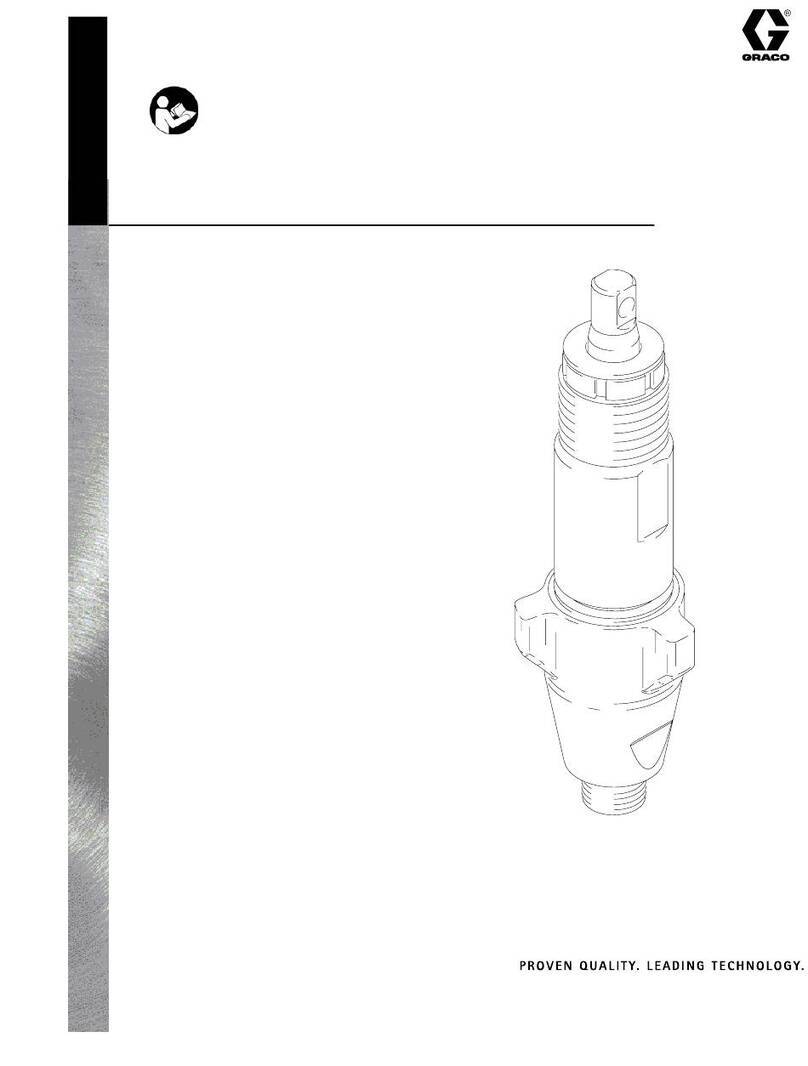
Graco Hydra-Cat A Series User manual

Instructions – Parts List
GRACO INC. P.O. BOX 1441 MINNEAPOLIS, MN 55440–1441
Copyright 2002, Graco Inc. is registered to I.S. EN ISO 9001
1:1 MIX RATIO PRESIDENTR
Hydra–CatrProportioning
Pump
600 psi (4.0 MPa, 40 bar) Maximum Working Pressure
Part No. 207914, Series E
1:1 Mix Ratio by Volume
Includes Model 215932 Displacement Pump
Part No. 903843, Series A
1:1 Mix Ratio by Volume
Includes Model 904287 Displacement Pump
*This model is certified and approved.
307001N
01328
*
*
Important Safety Instructions.
Read all warnings and instructions in this manual.
Save these instructions.
Parts
2307001
Table of Contents
Warnings 2. . . . . . . . . . . . . . . . . . . . . . . . . . . . . . . . . . . . . .
Installation 5. . . . . . . . . . . . . . . . . . . . . . . . . . . . . . . . . . . . .
Operation 6. . . . . . . . . . . . . . . . . . . . . . . . . . . . . . . . . . . . .
Troubleshooting 8. . . . . . . . . . . . . . . . . . . . . . . . . . . . . . . .
Service 9. . . . . . . . . . . . . . . . . . . . . . . . . . . . . . . . . . . . . . .
Parts 10. . . . . . . . . . . . . . . . . . . . . . . . . . . . . . . . . . . . . . . .
Technical Data 11. . . . . . . . . . . . . . . . . . . . . . . . . . . . . . . .
Mounting Hole Layout 11. . . . . . . . . . . . . . . . . . . . . . . . . .
Dimensions 11. . . . . . . . . . . . . . . . . . . . . . . . . . . . . . . . . . .
Graco Warranty 12. . . . . . . . . . . . . . . . . . . . . . . . . . . . . . .
Graco Information 12. . . . . . . . . . . . . . . . . . . . . . . . . . . . .
Symbols
Warning Symbol
WARNING
This symbol alerts you to the possibility of serious
injury or death if you do not follow the instructions.
Caution Symbol
CAUTION
This symbol alerts you to the possibility of damage to
or destruction of equipment if you do not follow the
corresponding instructions.
WARNING
EQUIPMENT MISUSE HAZARD
Equipment misuse can cause the equipment to rupture or malfunction and result in serious injury.
DThis equipment is for professional use only.
DRead all instruction manuals, tags, and labels before operating the equipment.
DUse the equipment only for its intended purpose. If you are uncertain about usage, call your Graco
distributor.
DDo not alter or modify this equipment. Use only genuine Graco parts and accessories.
DCheck the equipment daily. Repair or replace worn or damaged parts immediately.
DDo not exceed the maximum working pressure of the lowest rated system component. This equip-
ment has a 600 psi (4.0 MPa, 40 bar) maximum working pressure.
DDo not lift pressurized equipment.
DRoute the hoses away from the traffic areas, sharp edges, moving parts, and hot surfaces. Do not
expose Graco hoses to temperatures above 180_F (82_C) or below –40_F (–40_C).
DDo not use the hoses to pull the equipment.
DUse only Graco approved hoses. Do not remove hose spring guards, which help protect the hose
from rupture caused by kinks or bends near the couplings.
DUse fluids or solvents that are compatible with the equipment wetted parts. See the Technical
Data section of all the equipment manuals. Read the fluid and solvent manufacturer’s warnings.
DWear hearing protection when operating this equipment.
DComply with all applicable local, state and national fire, electrical and other safety regulations.
Warnings are continued on the next page.
3307001
WARNING
PRESSURIZED EQUIPMENT HAZARD
Spray from the gun, hose leaks, or ruptured components can splash fluid in the eyes or on the skin
and cause serious injury.
DDo not stop or deflect fluid leaks with your hand, body, glove, or rag.
DFollow the Pressure Relief Procedure on page 6 whenever you: are instructed to relieve the
pressure; stop spraying; clean, check, or service the equipment; and install or clean the fluid
nozzle.
DTighten all the fluid connections before operating the equipment.
DCheck the hoses, tubes, and couplings daily. Replace worn, damaged, or loose parts immediately.
Permanently coupled hoses cannot be repaired; replace the entire hose.
FIRE AND EXPLOSION HAZARD
Improper grounding, poor air ventilation, open flames, or sparks can cause a hazardous condition and
result in fire or explosion and serious injury.
DGround the equipment and the object being sprayed. See Grounding on page 5.
DProvide fresh air ventilation to avoid the buildup of flammable fumes from solvent or the fluid being
sprayed.
DExtinguish all the open flames or pilot lights in the spray area.
DElectrically disconnect all the equipment in the spray area.
DKeep the spray area free of debris, including solvent, rags, and gasoline.
DDo not turn on or off any light switch in the spray area while operating or if fumes are present.
DDo not smoke in the spray area.
DDo not operate a gasoline engine in the spray area.
DIf there is any static sparking while using the equipment, stop spraying immediately. Identify and
correct the problem.
TOXIC FLUID HAZARD
Hazardous fluid or toxic fumes can cause serious injury or death if splashed in the eyes or on the skin,
inhaled, or swallowed.
DKnow the specific hazards of the fluid you are using.
DStore hazardous fluid in an approved container. Dispose of hazardous fluid according to all local,
state and national guidelines.
DAlways wear protective eyewear, gloves, clothing and respirator as recommended by the fluid and
solvent manufacturer.
DGraco does not manufacture or supply the reactive chemical components that may be used in this
equipment and is not responsible for injury or property loss, damage, expense, or claims (direct or
consequential) that arise from the use of such chemical components.
4307001
Notes
5307001
Installation
General
Note: Reference numbers and letters in parentheses
in the text refer to the callouts in the figures and parts
drawings.
DThese pumps are designed to be part of a Hydra-
CatRsprayer that will proportion, mix, and spray
polyurethane chemicals. Refer to your separate
Hydra-CatRinstructions. If you are using this
pump to mix antifreeze and water, refer to page 9
for special plumbing instructions.
DMount the pump to suit the type of installation
planned. The pump dimensions and mounting hole
layout are shown on page 11.
DThe pump is supplied with a 3/4 npt(m) intake
nipple. If your installation requires a 3/4 npt(f) or 1”
npt(m) intake, remove and discard the 3/4 npt(m)
nipple, and connect your plumbing directly to the
intake housing. Refer to manual 307430 for a parts
breakdown of the displacement pump.
WARNING
Two accessories are required in your system: a
bleed-type master air valve and a fluid drain valve.
These accessories help reduce the risk of serious
injury, including splashing in the eyes or on the
skin, and injury from moving parts if you are adjust-
ing or repairing the pump.
The bleed-type master air valve relieves air trapped
between this valve and the pump after the air is
shut off. Trapped air can cause the pump to cycle
unexpectedly. Locate the valve close to the pump.
The fluid drain valve assists in relieving fluid pres-
sure in the displacement pump, hose, and gun;
triggering the gun to relieve pressure may not be
sufficient.
Grounding
To reduce the risk of static sparking, ground the spray-
er and all other spray equipment used or located in the
spray area. Check your local electrical code for de-
tailed grounding instructions for your area and type of
equipment. Ground all of this spray equipment:
DPump: use a ground wire and clamp to connect the
sprayer to a true earth ground. See Fig. 1.
DFeed pumps: use a ground wire and clamp to
connect the pump to a true earth ground. See your
separate feed pump instruction manual.
DAir compressors: refer to manufacturer’s recom-
mendations.
DAir and Fluid Hoses: use only grounded hoses and
check resistance regularly.
DHeaters: wire into a properly grounded power
supply. If using a generator, be sure it is positively
connected to a true earth ground.
DSpray gun: obtain grounding through connection to
a properly grounded fluid hose and sprayer.
DFluid supply containers: according to local code.
DObject being sprayed: according to local code.
DAll solvent pails used when flushing, according to
local code. Use only metal pails, which are conduc-
tive, placed on a grounded surface. Do not place
the pail on a non-conductive surface, such as paper
or cardboard, which interrupts grounding continuity.
DTo maintain grounding continuity when flushing or
relieving pressure, always hold a metal part of the
gun firmly to the side of a grounded metal pail, then
trigger the gun.
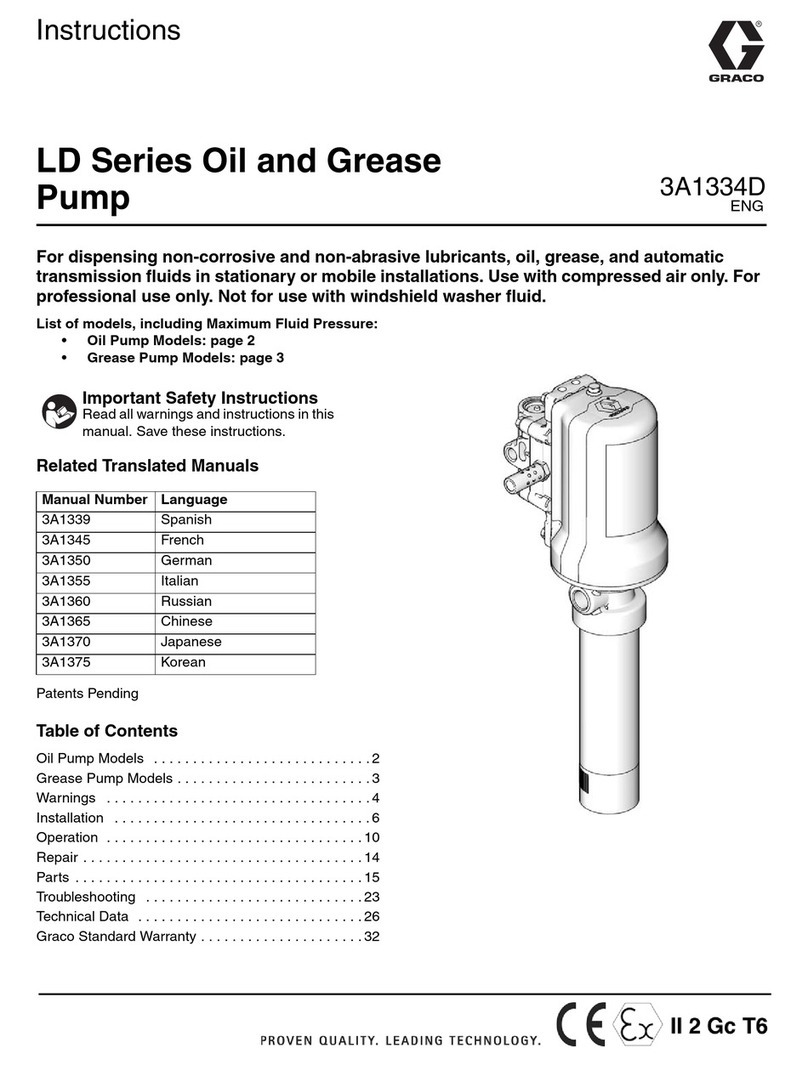
To ground the pump, loosen the grounding lug locknut
(W) and washer (X). Insert one end of a 12 ga (1.5
mm2) minimum ground wire (Y) into the slot in the lug
(Z) and tighten the locknut securely. See Fig. 1. Con-
nect the other end of the wire to a true earth ground.
Order Part No. 222011, grounding wire and clamp.
Fig. 1 0720
Y
W
X
Z
6307001
Operation
Pressure Relief Procedure
WARNING
PRESSURIZED EQUIPMENT HAZARD
The system pressure must be manually
relieved to prevent the system from
starting or spraying accidentally. To re-
duce the risk of an injury from accidental spray
from the gun, splashing fluid, or moving parts, fol-
low the Pressure Relief Procedure whenever you:
Dare instructed to relieve the pressure,
Dstop spraying,
Dcheck or service any of the system equipment,
Dor install or clean the fluid tips.
1. Shut off the air to the pump.
2. Close the bleed-type master air valve (required in
your system).
3. Hold a metal part of the dispensing valve firmly to
the side of a grounded metal waste container, and
trigger the gun to relieve pressure.
4. Open the drain valve (required in your system),
having a container ready to catch the drainage.
5. Leave the drain valve open until you are ready to
spray again.
If you suspect that the nozzle or hose is completely
clogged, or that pressure has not been fully relieved
after following the steps above, very slowly loosen the
hose end coupling and relieve pressure gradually, then
loosen completely. Now clear the obstruction. Refer to
your separate gun instruction manual, if necessary.
Fill the Wet Cups
Keep the wet-cups 1/3 full of ISO Pump Lube to pre-
vent fluid from drying on the displacement rod and
damaging the pump packings.
Flush the Pump
WARNING
To reduce the risk of serious injury whenever you
are instructed to relieve pressure, always follow the
Pressure Relief Procedure on page 6.
The displacement pump was factory tested in light oil,
which was left in to protect the pump parts. To prevent
contamination of the fluid being pumped, flush the
pump before using it. Be sure the solvent used is
compatible with the fluid being pumped.
Place each pump intake into a separate, grounded pail
of solvent. Direct the fluid outlet into a waste container.
Open the dispensing valve. Open the bleed-type
master air valve. Slowly open the pump air regulator
until the pump is running smoothly – about 40 psi (280
kPa, 2.8 bar). Operate the pump until clean solvent is
coming from the outlet. Relieve the pressure. If you
are flushing to prepare the pump for storage, leave the
pump and dispensing equipment filled with solvent to
help protect it from corrosion.
Startup and Priming
Note: These are general operating instructions for the
proportioning pump. Your specific installation may
require a slightly different startup procedure. Consult
your Graco representative if you have any questions.
1. Using proper moisture-control equipment for your
feed/supply pumps, place the RES (Resin) hose in
the RES supply container and the ISO (Isocya-
nate) hose in the ISO supply container.
2. Open the bleed-type master air valve and set the
pump air regulator to 40 psi (280 kPa) (2.8 bar).
Operate the pump until all air is purged from the
hoses, then close the air valve.
3. Prime the pump and hoses fully before connecting
to the dispensing gun or valve.
4. Connect the dispensing gun.
7307001
Operation
Using Your Proportioning System
When the system is primed and operating, check the
fluid outlet pressure gauges. Check the gauges fre-
quently when using the system. Always make a note of
the pressures indicated. These notes will be helpful in
analyzing any troubles that may occur since a change
in the displacement pump performance will be indi-
cated by a change in the pressure gauge readings.
Note: A pressure drop does occur during pump stroke
changeover.
Never exceed 120 psi (0.8 MPa, 8 bar) air pressure to
the pump.
WARNING
Always close the air supply valve to the pump
before operating the drain valves to relieve system
pressure. This will reduce the risk of excessive
pressure buildup in the opposite component hose
and fittings, and component rupture, which can
cause serious injury or property damage.
Lubrication and Care
WARNING
To reduce the risk of serious injury whenever you
are instructed to relieve pressure, always follow the
Pressure Relief Procedure on page 6.
Keep the wet cups/packing nuts 1/3 filled with ISO
Pump Oil and check the tightness of the packing nut
weekly. The packing nut should be tight enough to
prevent leakage – no tighter. Too tight an adjustment
will cause the packings to bind or wear prematurely
and leak. Always relieve the pressure before adjust-
ing the packing nut.
Never allow the supply containers to run dry of the fluid
being pumped. A dry container allows air to be
pumped into the system and cause incorrect propor-
tioning. One dry displacement pump can also damage
the other displacement pump because it causes a
pressure rise in the other pump. If the supply container
is dry, stop the pump immediately, refill the container,
and prime the system. Be sure to eliminate all of the
air from the system.
Always stop the pump at the bottom of its stroke to
prevent fluid from drying on the displacement pump
which can damage the throat packings.
Flush all fluid out of the displacement pump whenever
you shut down for overnight or longer and fill the pump
with mineral spirits or rust-inhibiting solvent to prevent
corrosion.
8307001
Troubleshooting
WARNING
To reduce the risk of serious injury whenever you
are instructed to relieve pressure, always follow the
Pressure Relief Procedure on page 6.
Note: Before servicing this equipment always make
sure to relieve the pressure.
Note: Check every possible problem and solution
before disassembling the pump.
Problem Cause Solution
Pump won’t run. Not enough air pressure or volume. Check, increase.
p
Closed or clogged air valve or line. Open, clear.
Air motor inoperative. Service. See manual 306982.
Pump runs, but RES output low on
upstroke*.
Dirty, worn, or damaged RES pump piston
valve.
Service. See manual 307430.
p
Worn or damaged RES pump piston
packings.
Service. See manual 307430.
Pump runs, but RES output low on
downstroke*.
Dirty, worn, or damaged RES pump intake
valve.
Clean, service. See manual 307430.
Pump runs, but RES output low on
both strokes*.
Dirty, worn, or damaged RES pump intake
valve.
Clean, service. See manual 307430.
Empty or inadequate fluid supply. Refill or change container.
Pump runs, but ISO output low on
upstroke*.
Dirty, worn, or damaged ISO pump piston
valve.
Service. See manual 307430.
p
Worn or damaged ISO pump piston pack-
ings.
Service. See manual 307430.
Pump runs, but ISO output low on
downstroke*.
Dirty, worn, or damaged ISO pump intake
valve.
Clean, service. See manual 307430.
Pump runs, but ISO output low on
both strokes*.
Dirty, worn, or damaged ISO pump intake
valve.
Clean, service. See manual 307430.
Empty or inadequate fluid supply. Refill or change container.
Fluid leaks around fluid pump packing
nut.
Loose packing nut or worn throat pack-
ings.
Tighten, replace. See manual 307430.
Pump speeds up or runs erratically. Empty or inadequate fluid supply. Refill or change container.
pp p y
Air in fluid lines. Purge, check connections.
* Fluids ratio will be wrong.
9307001
Service
WARNING
To reduce the risk of serious injury whenever you
are instructed to relieve pressure, always follow the
Pressure Relief Procedure on page 6.
Disassembly (Fig. 2)
1. Relieve the pressure.
2. Solvent flush the pump, if possible, and relieve
the pressure again.
3. Screw the shouldered nut (15) off the yoke (18).
4. Remove the four locknuts (8) from the tie rods (19)
and remove the tie plate (16) with the pumps (22)
and yoke still attached.
5. Remove the nuts and lockwashers (4 and 6) from
the pump displacement rods and remove the yoke.
6. Remove the three screws and lockwashers (4 and
6) holding each pump to the tie plate and remove
the pumps.
7. To service the air motor, refer to separate instruc-
tion manual 306982.
8. To service the displacement pumps, refer to sepa-
rate instruction manual 307430.
Reassembly (Fig. 2)
1. Place the displacement pumps in the tie plate (16)
and secure with the screws (4) and lockwashers
(6).
2. If the rod extensions (20) were removed, replace
them on the displacement rods and secure with
the cotter pins (9). Secure the rod extensions to
the yoke (18) with the lockwashers (5) and nuts
(7).
3. Position the tie rods (19) in the tie plate (16) and
install the nuts (8), torquing evenly to 30–50 ft-lb
(47–68 NSm).
4. Screw the shouldered nut (15) down onto the
yoke.
5. Reconnect the ground wire if it was disconnected
during service.
Mixing Antifreeze and Water
To ensure complete mixing, the outlet line should be at
least 1 in. diameter tubing or 3/4 in. pipe. Runs shorter
than 45 m (150 ft) should use a 100 mm (4 in.) diame-
ter x 0.9 m (36 in.) mixing chamber fabricated of
schedule 40 pipe.
The plumbing and suction lift to the pump inlets must
meet certain specifications so the volumes of the two
fluids supplied to the pump remain equal, to ensure
proper 1:1 proportioning. The inlet lines must be the
same diameter and length, with the same number of
bends or elbows. The lift requirements of the two inlets
can vary within a range of 0.45 m (18 in.). Use a float
valve set at the 0.45 m (18 in.) level of one of the fluid
supply tanks to ensure that the lift requirement is
maintained.
Fig. 2
7223A
1
15
4
6
81
19
18
7
5
16
22
Torque to
35–50 ft-lb
(47–68 NSm)
10 307001
Parts
TI0557B
Model 207914
Series E
Model 903843
Series A
21
14
2
1
15
17
9
7
5
18
20
9
4
6
22
16
8
10
19
4
6
23
Ref
No. Part No. Description Qty.
Ref
No. Part No. Description Qty.
1 100017 SCREW, hex hd cap;
1/2 in.–13 x 1.5 in. 3
2 100018 LOCKWASHER, spring; 1/2 in. size 3
4 100101 SCREW, hex hd cap;
3/8 in.–16 x 1.0 in. 9
5 100128 LOCKWASHER, spring; 5/8 in. 2
6 100133 LOCKWASHER, spring; 3/8 in. 9
7 100681 NUT, hex jam; 5/8 in.–11 2
8 101712 NUT, lock; 5/8 in.–11 4
9 101946 PIN, cotter; SST; 0.125 in. (3.2 mm)
dia; 1.50 in. (38.1 mm) lg 3
10 156082 O-RING; Model 903843 only 2
14 168418 PLATE, adapter 1
15 168453 NUT, shouldered 1
16 168600 PLATE, tie 1
17 168606 ROD, connecting 1
18 168607 YOKE, connecting 1
19 171313 ROD, tie; 10.687 in. (272 mm) 4
20 171314 EXTENSION, displacement rod 2
21 207352 AIR MOTOR;
See manual 306982 for parts 1
22 215932 DISPLACEMENT PUMP ASSY
See manual 307430 for parts
Model 207914 only 2
904287 DISPLACEMENT PUMP ASSY
See manual 307430 for parts
Model 903843 only 2
23 178471 PLATE, mounting 1
11307001
Technical Data
Category Data
Weight 65 lb (29.5 kg)
Air Operating Range 40–120 psi (0.28–0.84 MPa, 2.8–8.4 bar)
Air Consumption Approximately 20 cfm per gallon pumped
(0.13 m3/min/liter) at 100 psi (0.7 MPa, 7 bar)
Pump Cycles per Gallon (3.8 liter) 10
Maximum Recommended Pump Speed 60 cycles/min; 6 gpm (22.8 liters/min)
Recommended Speed for Optimum Pump Life 20–40 cpm
Wetted Parts Stainless Steel, nitralloy steel, Buna-n, PTFE
Mounting Hole
Layout Dimensions
7225A
4.75 in.
(121mm)
Square Cutout
Four 0.438 in. (11.1 mm)
Holes on 5.5 in.
(140 mm)
Bolt Circle
7224A
6.375 in.
(162 mm)
1/2 npt(f)
Fluid Outlet
3/4 npt(f), 1 in. npt(m),
1–1/2 in. npt(m),
or 3/4 npt(m) Fluid Inlet
1/2 npt(f)
Air Inlet
35.94 in.
(913 mm)
20.19 in.
(513 mm)
12 307001
Graco Standard Warranty
Graco warrants all equipment manufactured by Graco and bearing its name to be free from defects in material and workmanship on the
date of sale to the original purchaser for use. With the exception of any special, extended, or limited warranty published by Graco,
Graco will, for a period of twelve months from the date of sale, repair or replace any part of the equipment determined by Graco to be
defective. This warranty applies only when the equipment is installed, operated and maintained in accordance with Graco’s written
recommendations.
This warranty does not cover, and Graco shall not be liable for general wear and tear, or any malfunction, damage or wear caused by
faulty installation, misapplication, abrasion, corrosion, inadequate or improper maintenance, negligence, accident, tampering, or sub-
stitution of non–Graco component parts. Nor shall Graco be liable for malfunction, damage or wear caused by the incompatibility of
Graco equipment with structures, accessories, equipment or materials not supplied by Graco, or the improper design, manufacture,
installation, operation or maintenance of structures, accessories, equipment or materials not supplied by Graco.
This warranty is conditioned upon the prepaid return of the equipment claimed to be defective to an authorized Graco distributor for
verification of the claimed defect. If the claimed defect is verified, Graco will repair or replace free of charge any defective parts. The
equipment will be returned to the original purchaser transportation prepaid. If inspection of the equipment does not disclose any defect
in material or workmanship, repairs will be made at a reasonable charge, which charges may include the costs of parts, labor, and
transportation.
THIS WARRANTY IS EXCLUSIVE, AND IS IN LIEU OF ANY OTHER WARRANTIES, EXPRESS OR IMPLIED, INCLUDING BUT
NOT LIMITED TO WARRANTY OF MERCHANTABILITY OR WARRANTY OF FITNESS FOR A PARTICULAR PURPOSE.
Graco’s sole obligation and buyer’s sole remedy for any breach of warranty shall be as set forth above. The buyer agrees that no other
remedy (including, but not limited to, incidental or consequential damages for lost profits, lost sales, injury to person or property, or any
other incidental or consequential loss) shall be available. Any action for breach of warranty must be brought within two (2) years of the
date of sale.
Graco makes no warranty, and disclaims all implied warranties of merchantability and fitness for a particular purpose in connection
with accessories, equipment, materials or components sold but not manufactured by Graco. These items sold, but not manufactured
by Graco (such as electric motors, switches, hose, etc.), are subject to the warranty, if any, of their manufacturer. Graco will provide
purchaser with reasonable assistance in making any claim for breach of these warranties.
In no event will Graco be liable for indirect, incidental, special or consequential damages resulting from Graco supplying equipment
hereunder, or the furnishing, performance, or use of any products or other goods sold hereto, whether due to a breach of contract,
breach of warranty, the negligence of Graco, or otherwise.
FOR GRACO CANADA CUSTOMERS
The parties acknowledge that they have required that the present document, as well as all documents, notices and legal proceedings
entered into, given or instituted pursuant hereto or relating directly or indirectly hereto, be drawn up in English. Les parties reconnais-
sent avoir convenu que la rédaction du présente document sera en Anglais, ainsi que tous documents, avis et procédures judiciaires
exécutés, donnés ou intentés à la suite de ou en rapport, directement ou indirectement, avec les procedures concernées.
Graco Information
TO PLACE AN ORDER, contact your Graco distributor, or call one of the following numbers
to identify the distributor closest to you:
1–800–328–0211 Toll Free
612–623–6921
612–378–3505 Fax
All written and visual data contained in this document reflects the latest product information available at the time of publication.
Graco reserves the right to make changes at any time without notice.
MM 307001
Graco Headquarters: Minneapolis
International Offices: Belgium, China, Japan, Korea
GRACO INC. P.O. BOX 1441 MINNEAPOLIS, MN 55440–1441
PRINTED IN U.S.A. 307001 07/1969, Revised 06/2005

This manual suits for next models

3

Other Graco Water Pump manuals

Graco Core E1 Use and care manual

Graco

Graco Core E1 Use and care manual

Graco President 224 757 User manual

Graco

Graco President 224 757 User manual

Graco HIGH-FLO 243737 User manual

Graco

Graco HIGH-FLO 243737 User manual

Graco PRESIDENT HYDRA-CAT 231657 Operation manual

Graco

Graco PRESIDENT HYDRA-CAT 231657 Operation manual

Graco 3A1335A User manual

Graco

Graco 3A1335A User manual

Graco E-Flo EC1110 Operation manual

Graco

Graco E-Flo EC1110 Operation manual

Graco Injecto-Flo II Single Line User manual

Graco

Graco Injecto-Flo II Single Line User manual

Graco HUSKY 1050P User manual

Graco

Graco HUSKY 1050P User manual

Graco Python A25177 User manual

Graco

Graco Python A25177 User manual

Graco NXT Air Motor M02LN0 Parts list manual

Graco

Graco NXT Air Motor M02LN0 Parts list manual

Graco Fast-Ball 222103 User manual

Graco

Graco Fast-Ball 222103 User manual

Graco LD Series User manual

Graco

Graco LD Series User manual

Graco saniforce 2150 User manual

Graco

Graco saniforce 2150 User manual

Graco Dura-Flo 236464 Operation manual

Graco

Graco Dura-Flo 236464 Operation manual

Graco Hydra-Clean 1040 Parts list manual

Graco

Graco Hydra-Clean 1040 Parts list manual

Graco SaniForce 24E836 Parts list manual

Graco

Graco SaniForce 24E836 Parts list manual

Graco SaniForce 24E836 Parts list manual

Graco

Graco SaniForce 24E836 Parts list manual

Graco Bulldog User manual

Graco

Graco Bulldog User manual

Graco Husky 15120 Use and care manual

Graco

Graco Husky 15120 Use and care manual

Graco G3 Pro User manual

Graco

Graco G3 Pro User manual

Graco 257100 Instruction Manual

Graco

Graco 257100 Instruction Manual

Graco Merkur A Series Parts list manual

Graco

Graco Merkur A Series Parts list manual

Graco HIP e710 Series Operation manual

Graco

Graco HIP e710 Series Operation manual

Graco Fast-Flo Datasheet

Graco

Graco Fast-Flo Datasheet

Popular Water Pump manuals by other brands

Edwards RV3 instruction manual

Edwards

Edwards RV3 instruction manual

Neptun NFP 75 operating instructions

Neptun

Neptun NFP 75 operating instructions

ITT Goulds Pump SP02 manual

ITT

ITT Goulds Pump SP02 manual

Edwards E2MO.7 instruction manual

Edwards

Edwards E2MO.7 instruction manual

Finish Thompson EF Series Operations & parts manual

Finish Thompson

Finish Thompson EF Series Operations & parts manual

Stuart Turner Supersub 460A operating instructions

Stuart Turner

Stuart Turner Supersub 460A operating instructions

American Plumber W-SU40TB owner's manual

American Plumber

American Plumber W-SU40TB owner's manual

TotalPond MD11400ASL manual

TotalPond

TotalPond MD11400ASL manual

KSB Amarex KRT Installation & operating manual

KSB

KSB Amarex KRT Installation & operating manual

WilTec XPOtool 63444 Operation manual

WilTec

WilTec XPOtool 63444 Operation manual

BJM Pumps SKG FAHRENHEIT Series Installation, operation & maintenance manual

BJM Pumps

BJM Pumps SKG FAHRENHEIT Series Installation, operation & maintenance manual

Swim & Fun SMART Optima Pump manual

Swim & Fun

Swim & Fun SMART Optima Pump manual

Star 148014 1HP manual

Star

Star 148014 1HP manual

SFA Sanicondens Clim mini S Operating & installation manual

SFA

SFA Sanicondens Clim mini S Operating & installation manual

Hanna Instruments BL1.5 instruction manual

Hanna Instruments

Hanna Instruments BL1.5 instruction manual

Grundfos PF Series Installation and operating instructions

Grundfos

Grundfos PF Series Installation and operating instructions

Triton T22i Installation and operating instructions

Triton

Triton T22i Installation and operating instructions

Zoeller 7008 owner's manual

Zoeller

Zoeller 7008 owner's manual

manuals.online logo
manuals.online logoBrands
  • About & Mission
  • Contact us
  • Privacy Policy
  • Terms and Conditions

Copyright 2025 Manuals.Online. All Rights Reserved.