manuals.online logo
Brands
  1. Home
  2. •
  3. Brands
  4. •
  5. Graco
  6. •
  7. Water Pump
  8. •
  9. Graco Series A Operation manual

Graco Series A Operation manual

Other manuals for Series A

66

This manual suits for next models

1

Other Graco Water Pump manuals

Graco AGP-U100 User manual

Graco

Graco AGP-U100 User manual

Graco Dyna-Star 77X000 User manual

Graco

Graco Dyna-Star 77X000 User manual

Graco 248061 User manual

Graco

Graco 248061 User manual

Graco ProMix PD2K User manual

Graco

Graco ProMix PD2K User manual

Graco Series A Operating instructions

Graco

Graco Series A Operating instructions

Graco SaniForce 1590 HS Operation manual

Graco

Graco SaniForce 1590 HS Operation manual

Graco 246830 User manual

Graco

Graco 246830 User manual

Graco 260549 Operation manual

Graco

Graco 260549 Operation manual

Graco Wolverine A261 Series Operation manual

Graco

Graco Wolverine A261 Series Operation manual

Graco 563918 User manual

Graco

Graco 563918 User manual

Graco Mini Fire-Ball 225 Operation manual

Graco

Graco Mini Fire-Ball 225 Operation manual

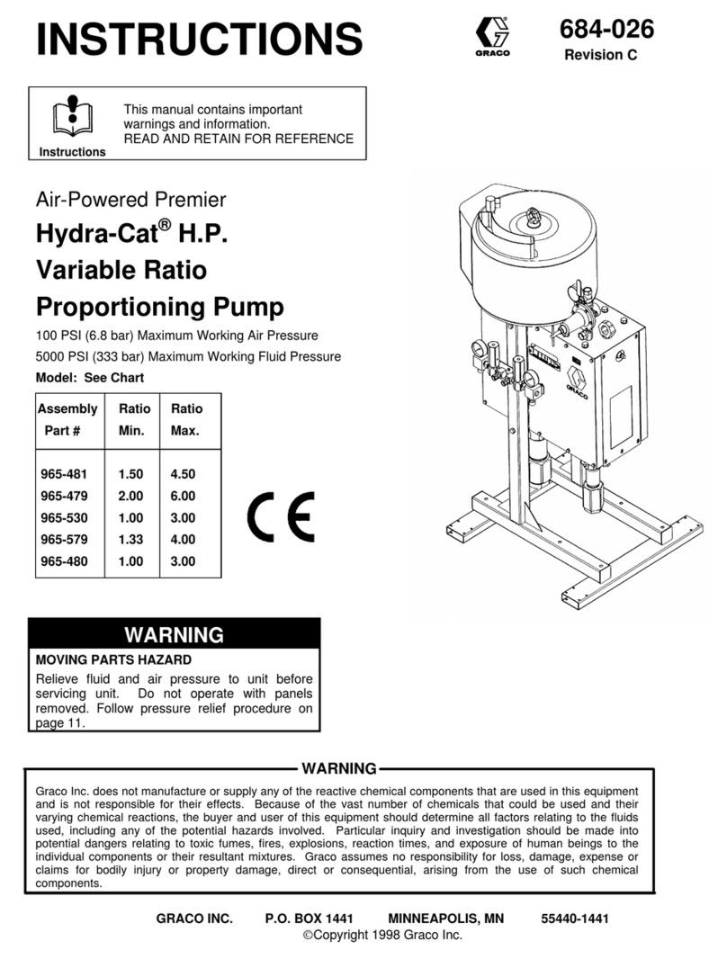
Graco Hydra-Cat H.P. Series User manual

Graco

Graco Hydra-Cat H.P. Series User manual

Graco GH 675 Operating instructions

Graco

Graco GH 675 Operating instructions

Graco EP2 User manual

Graco

Graco EP2 User manual

Graco 226-249 Operation manual

Graco

Graco 226-249 Operation manual

Graco Standard 946-964 User manual

Graco

Graco Standard 946-964 User manual

Graco Fire-Ball 300 User manual

Graco

Graco Fire-Ball 300 User manual

Graco 25C782 User manual

Graco

Graco 25C782 User manual

Graco D200 Operating instructions

Graco

Graco D200 Operating instructions

Graco Dyna-Star 239882 Operation manual

Graco

Graco Dyna-Star 239882 Operation manual

Graco 96G017 User manual

Graco

Graco 96G017 User manual

Graco 232200 Operation manual

Graco

Graco 232200 Operation manual

Graco DM-22 User manual

Graco

Graco DM-22 User manual

Graco 244731 Operation manual

Graco

Graco 244731 Operation manual

Popular Water Pump manuals by other brands

Watershed Innovations HYDRAPUMP SMART FLEX Instructional manual

Watershed Innovations

Watershed Innovations HYDRAPUMP SMART FLEX Instructional manual

Messner MultiSystem MPF 3000 operating instructions

Messner

Messner MultiSystem MPF 3000 operating instructions

Xylem Bell & Gossett WEHT0311M Installation, operation and maintenance instructions

Xylem

Xylem Bell & Gossett WEHT0311M Installation, operation and maintenance instructions

WilTec 50739 Operation manual

WilTec

WilTec 50739 Operation manual

Franklin Electric Little Giant 555702 HRK-360S instruction sheet

Franklin Electric

Franklin Electric Little Giant 555702 HRK-360S instruction sheet

Ingersoll-Rand PD02P Series Operator's manual

Ingersoll-Rand

Ingersoll-Rand PD02P Series Operator's manual

VS ZJ Series Operating	 instruction

VS

VS ZJ Series Operating instruction

Flotec FPZS50RP owner's manual

Flotec

Flotec FPZS50RP owner's manual

SKF Lincoln FlowMaster II User and maintenance instructions

SKF

SKF Lincoln FlowMaster II User and maintenance instructions

Xylem Lowara LSB Series Installation, operation and maintenance instructions

Xylem

Xylem Lowara LSB Series Installation, operation and maintenance instructions

Water Duro Pumps DCJ500 Operating & installation instructions

Water

Water Duro Pumps DCJ500 Operating & installation instructions

Action P490 Operating instructions & parts manual

Action

Action P490 Operating instructions & parts manual

Flo King Permacore Reusable Carbon Bag Disassembly. & Cleaning Instructions

Flo King

Flo King Permacore Reusable Carbon Bag Disassembly. & Cleaning Instructions

ARO ARO PD15P-X Operator's manual

ARO

ARO ARO PD15P-X Operator's manual

Pumptec 112V Series Operating instructions and parts manual

Pumptec

Pumptec 112V Series Operating instructions and parts manual

Virax 262070 user manual

Virax

Virax 262070 user manual

Neptun NPHW 5500 operating instructions

Neptun

Neptun NPHW 5500 operating instructions

Sensidyne Gilian BDX-II Operation & service manual

Sensidyne

Sensidyne Gilian BDX-II Operation & service manual

manuals.online logo
manuals.online logoBrands
  • About & Mission
  • Contact us
  • Privacy Policy
  • Terms and Conditions

Copyright 2025 Manuals.Online. All Rights Reserved.

Corrosion
Control
Equipment
and
Supplies
Distributed by:!
Houston Office:
248 McCarty Dr.
Houston, TX 77029-1195
(713) 672-8251
Fax (713) 672-6636
Dallas Branch:
4770 Gretna
Dallas, TX 75207
(214) 631-0584
Fax (214) 631-5824
1-800-BLAST 97
Corpus Christi Branch:
4750 Westway
Corpus Chrisi, TX 78408
(361) 882-8282
Fax (361) 882-6029
1-800-CLEMTEX
www.clemtex.com
[email protected]
Instructions – Parts List
!"#$%&'($)*+)%)&,%-&.//.*0'((1#+%2'34&0(*55//67.//.
!"#$%&'()*+,,-.*/%01"*2314*&5*%6'&5)6%67*)"*2484*9:*28;*,<<+
2” BUNG MOUNT, 200 LITER (55 GALLON) DRUM SIZE
10:1 Ratio President!Pump
Part No. 239326, Series A
62 bar (6.2 MPa, 900 psi) Maximum Fluid Working Pressure
6.2 bar (0.62 MPa, 90 psi) Maximum Air Input Pressure
308738C
Read warnings and instructions.
Refer to page 2 for the Table of Contents.
0359
ITS03ATEX11228
II 1/2 G T2
! "#$%"$
Table of Contents
Warnings 2. . . . . . . . . . . . . . . . . . . . . . . . . . . . . . . . . . . . . .
Installation 5. . . . . . . . . . . . . . . . . . . . . . . . . . . . . . . . . . . . .
Operation 8. . . . . . . . . . . . . . . . . . . . . . . . . . . . . . . . . . . . .
Troubleshooting 10. . . . . . . . . . . . . . . . . . . . . . . . . . . . . . .
Service 11. . . . . . . . . . . . . . . . . . . . . . . . . . . . . . . . . . . . . .
Parts 12. . . . . . . . . . . . . . . . . . . . . . . . . . . . . . . . . . . . . . . .
Dimensions 13. . . . . . . . . . . . . . . . . . . . . . . . . . . . . . . . . . .
Technical Data 14. . . . . . . . . . . . . . . . . . . . . . . . . . . . . . . .
Warranty 16. . . . . . . . . . . . . . . . . . . . . . . . . . . . . . . . . . . . .
Graco Information 16. . . . . . . . . . . . . . . . . . . . . . . . . . . . .
Symbols
Warning Symbol
WARNING
This symbol alerts you to the possibility of serious
injury or death if you do not follow the instructions.
Caution Symbol
CAUTION
This symbol alerts you to the possibility of damage to
or destruction of equipment if you do not follow the
corresponding instructions.
WARNING
INSTRUCTIONS
EQUIPMENT MISUSE HAZARD
Equipment misuse can cause the equipment to rupture or malfunction and result in serious injury.
"This equipment is for professional use only.
"Read all instruction manuals, tags, and labels before operating the equipment.
"Use the equipment only for its intended purpose. If you are uncertain about usage, call your Graco
distributor.
"Do not alter or modify this equipment. Use only genuine Graco parts and accessories.
"Check equipment daily. Repair or replace worn or damaged parts immediately.
"Do not exceed the maximum working pressure of the lowest rated system component. Refer to the
Technical Data on page 14 for the maximum working pressure of this equipment.
"Use fluids and solvents which are compatible with the equipment wetted parts. Refer to the Tech-
nical Data section of all equipment manuals. Read the fluid and solvent manufacturer’s warnings.
"Do not use hoses to pull equipment.
"Route hoses away from traffic areas, sharp edges, moving parts, and hot surfaces. Do not expose
Graco hoses to temperatures above 82#C (180#F) or below –40#C (–40#F).
"Wear hearing protection when operating this equipment.
"Do not lift pressurized equipment.
"Comply with all applicable local, state, and national fire, electrical, and safety regulations.
"#$%"$ "
WARNING
INJECTION HAZARD
Spray from the gun/valve, hose leaks, or ruptured components can inject fluid into your body and
cause extremely serious injury, including the need for amputation. Fluid splashed in the eyes or on the
skin can also cause serious injury.
"Fluid injected into the skin might look like just a cut, but it is a serious injury. Get immediate medi-
cal attention.
"Do not point the gun/valve at anyone or at any part of the body.
"Do not put your hand or fingers over the spray tip/nozzle.
"Do not stop or deflect leaks with your hand, body, glove or rag.
"Do not “blow back” fluid; this is not an air spray system.
"Always have the tip guard and the trigger guard on the gun when spraying.
"Check the gun diffuser operation weekly. Refer to the gun manual.
"Be sure the gun/valve trigger safety operates before spraying/dispensing.
"Lock the gun/valve trigger safety when you stop spraying/dispensing.
"Follow the Pressure Relief Procedure on page 8 whenever you: are instructed to relieve pres-
sure; stop spraying/dispensing; clean, check, or service the equipment; and install or clean the
spray tip/nozzle.
"Tighten all fluid connections before operating the equipment.
"Check the hoses, tubes, and couplings daily. Replace worn, damaged, or loose parts immediately.
Permanently coupled hoses cannot be repaired; replace the entire hose.
"Use only Graco approved hoses. Do not remove any spring guard that is used to help protect the
hose from rupture caused by kinks or bends near the couplings.
MOVING PARTS HAZARD
Moving parts, such as the air motor piston, can pinch or amputate your fingers.
"Keep clear of all moving parts when starting or operating the pump.
"Before servicing the equipment, follow the Pressure Relief Procedure on page 8 to prevent the
equipment from starting unexpectedly.
& "#$%"$
WARNING
FIRE AND EXPLOSION HAZARD
Improper grounding, poor ventilation, open flames or sparks can cause a hazardous condition and
result in a fire or explosion and serious injury.
"Ground the equipment and the object being sprayed. Refer to Grounding on page 5.
"If there is any static sparking or you feel an electric shock while using this equipment, stop spray-
ing/dispensing immediately. Do not use the equipment until you identify and correct the problem.
"Provide fresh air ventilation to avoid the buildup of flammable fumes from solvents or the fluid
being sprayed/dispensed.
"Keep the spray/dispense area free of debris, including solvent, rags, and gasoline.
"Electrically disconnect all equipment in the spray/dispense area.
"Extinguish all open flames or pilot lights in the spray/dispense area.
"Do not smoke in the spray/dispense area.
"Do not turn on or off any light switch in the spray/dispense area while operating or if fumes are
present.
"Do not operate a gasoline engine in the spray/dispense area.
TOXIC FLUID HAZARD
Hazardous fluid or toxic fumes can cause serious injury or death if splashed in the eyes or on the skin,
inhaled, or swallowed.
"Know the specific hazards of the fluid you are using.
"Store hazardous fluid in an approved container. Dispose of hazardous fluid according to all local,
state and national guidelines.
"Always wear protective eyewear, gloves, clothing and respirator as recommended by the fluid and
solvent manufacturer.
"#$%"$ '
Installation
NOTES:
"Reference numbers and letters in parentheses in
the text refer to the callouts in the figures and
drawings.
"Always use Genuine Graco Parts and Accessories,
available from your Graco distributor. If you supply
your own accessories, be sure they are adequately
sized and pressure-rated to meet the system’s
requirements.
"Fig. 2 is only a guide for selecting and installing
system components and accessories. Contact your
Graco distributor for assistance in designing a
system to suit your particular needs.
Prepare the Operator
All persons who operate the equipment must be
trained in the safe, efficient operation of all system
components as well as the proper handling of all fluids.
All operators must thoroughly read all instruction
manuals, tags, and labels before operating the
equipment.
Prepare the Site
Ensure that you have an adequate compressed air
supply. Refer to the performance chart on page 15 to
find the air consumption of your pump.
Keep the site clear of any obstacles or debris that
could interfere with the operator’s movement.
Have a grounded, metal pail available for use when
flushing the system.
Mounting the Pump
Screw the bung adapter (B) tightly into the drum bung
hole and tighten the thumbscrew to hold the pump
about 13 mm (0.5 in.) off the bottom of the drum.
Loosen the drum vent plug to prevent forming a
vacuum. The pump dimensions are shown on page 13.
Grounding
WARNING
FIRE AND EXPLOSION HAZARD
Before operating the pump, ground the
system as explained below. Also read
the section FIRE AND EXPLOSION
HAZARD on page 4.
"Pump: Use a ground wire and clamp. See Fig.1.
Loosen the grounding lug locknut (W) and washer
(X). Insert one end of a 12 ga (1.5 mm$) minimum
ground wire (Y) into the slot in lug (Z) and tighten
the locknut securely. Connect the other end of the
wire to a true earth ground. For a ground wire and
clamp, order Part No. 237569.
W
Y
X
Z
!"#!
Fig. 1
"Air and fluid hoses: Use only electrically conductive
hoses with 150 m (500 ft) maximum combined hose
length to ensure grounding continuity.
"Air compressor: Follow manufacturer’s
recommendations.
"Spray gun or dispensing valve: Connect to a
properly grounded fluid hose and pump.
"Object being sprayed: Follow your local code.
"Fluid supply container: Follow your local code.
"Solvent pails used when flushing: Follow your local
code. Use only metal pails, which are conductive,
placed on a grounded surface. Do not place the
pail on a nonconductive surface, such as paper or
cardboard, which interrupts the grounding
continuity.
"To maintain proper grounding continuity when
flushing or relieving pressure, always hold the metal
part of the spray gun/dispense valve firmly to the
side of a grounded metal pail, then trigger the
gun/valve.
( "#$%"$
Installation
Typical Installation
Fig. 2
KEY
APump
BBung adapter
CAir line lubricator
DBleed-type master air valve (required for pump)
See Warning on page 7 for part number.
EPump air regulator
FAir line filter
GBleed-type master air valve (for accessories)
HElectrically conductive air supply hose
JAir line moisture trap and drain valve
KPump runaway valve
LFluid drain valve (required)
See Warning on page 7 for part numbers.
MElectrically conductive fluid supply hose
YGround wire (required)
Part No. 237569. See page 5 for installation instructions.
J
A
CDE
FG
H
L
Y
B
K
M
07201
"#$%"$ %
Installation
System Accessories
WARNING
A bleed-type master air valve (D) and a fluid drain
valve (L) are required in your system. These
accessories help reduce the risk of serious injury
including fluid injection, splashing in the eyes or on
the skin, and injury from moving parts if you are
adjusting or repairing the pump.
The bleed-type master air valve relieves air trapped
between this valve and the pump after the air is
shut off. Trapped air can cause the pump to cycle
unexpectedly. Locate the valve close to the pump.
Order Part No. 113333.
The fluid drain valve assists in relieving fluid pres-
sure in the displacement pump, hose, and gun.
Triggering the gun to relieve pressure may not be
sufficient. Order one of the following:
Part No. Description
238635 1/4 npt (mbe), carbon steel
210657 1/4 npt (mbe), carbon steel
210658 3/8 npt (mbe), carbon steel
210659 1/4 npt x 3/8 npt (mbe), carbon steel
239018 1/4 npt (mbe), stainless steel
235992 1/4 npt x 3/8 npt (mbe), stainless steel
Air and Fluid Hoses
Be sure all air and fluid hoses are properly sized and
pressure-rated for your system. Use only electrically
conductive air and fluid hoses. Use a 13 mm (1/2 in.)
I.D. (minimum) air hose (H) to supply air to the pump.
Fluid hoses must have spring guards on both ends.
Connect a fluid hose (M) to the pump’s 3/4 npt(f) fluid
outlet. Use of a short whip hose between the main
fluid hose and the gun allows freer gun movement.
Air Line Accessories
Install the following accessories in the order shown in
Fig. 2, using adapters as necessary:
"Air line lubricator (C)
Provides automatic air motor lubrication.
"Bleed-type master air valve (D)
Required in your system to relieve air trapped
between it and the air motor when the valve is
closed (see the WARNING at left). Be sure the
bleed valve is easily accessible from the pump, and
is located downstream from the air regulator (E).
"Air regulator (E)
Controls pump speed and outlet pressure by
adjusting the air pressure to the pump. Locate the
regulator close to the pump, but upstream from the
bleed-type master air valve (D).
"Pump runaway valve (K)
Senses if the pump is running too fast and shuts off
the air supply to the motor. A pump which runs too
fast can be seriously damaged.
"Air line filter (F)
Install an air line filter (F) and a moisture trap and
drain valve (J) to help remove moisture and
contaminants from the compressed air supply.
"Second bleed-type air valve (G)
Isolates the air line accessories for servicing.
Locate upstream from all other air line accessories.
Fluid Line Accessories
Install the following accessories in the positions shown
in Fig. 2, using adapters as necessary:
"Fluid drain valve (L)
Required in your system to relieve fluid pressure in
the hose and gun (see the WARNING at left).
Install the drain valve so that it points down and the
handle points up when it is opened.
$ "#$%"$
Operation
Pressure Relief Procedure
WARNING
INJECTION HAZARD
The system pressure must be manually
relieved to prevent the system from
starting or spraying accidentally. Fluid
under high pressure can be injected through the
skin and cause serious injury. To reduce the risk of
an injury from injection, splashing fluid, or moving
parts, follow the Pressure Relief Procedure
whenever you:
"are instructed to relieve the pressure,
"stop spraying,
"check or service any of the system equipment,
"or install or clean the spray tip.
1. Lock the gun trigger safety.
2. Shut off the air supply to the pump.
3. Close the bleed-type master air valve (required in
your system).
4. Unlock the gun/valve trigger safety.
5. Hold a metal part of the gun/valve firmly to the side
of a grounded metal pail, and trigger the gun/valve
to relieve pressure.
6. Lock the gun/valve trigger safety.
7. Open the drain valve (required in your system),
and have a container ready to catch the drainage.
8. Leave the drain valve open until you are ready to
spray again.
If you suspect that the spray tip/nozzle or hose is
completely clogged, or that pressure has not been fully
relieved after following the steps above, very slowly
loosen the tip guard retaining nut or hose end coupling
and relieve pressure gradually, then loosen it
completely. Then clear the tip/nozzle or hose.
Flush the Pump Before First Use
The pump is tested with lightweight oil, which is left in
to protect the pump parts. If the fluid you are using
may be contaminated by the oil, flush it out with a
compatible solvent before using the pump. If the pump
is being used to supply a circulating system, allow the
solvent to circulate until the pump is thoroughly
flushed. See Flushing the Pump on page 9.
Packing Nut/Wet-Cup
WARNING
To reduce the risk of serious injury whenever you
are instructed to relieve pressure, always follow the
Pressure Relief Procedure at left.
Keep the packing nut/wet-cup (S) filled with Graco
Throat Seal Liquid (TSL) or compatible solvent to help
prolong the packing life. Check the tightness of the
packing nut weekly; tighten just enough to prevent
leakage; do not overtighten it. See Fig. 3 on page 11.
Relieve the pressure before adjusting the packing nut
or adding TSL.
Starting and Adjusting the Pump
Begin these steps before you install the spray
tip/nozzle.
1. Ensure that the air regulator (E) and bleed-type
master air valve (D) are closed. See Fig. 2 on
page 6.
2. Hold a metal part of the gun/valve firmly to the side
of a grounded metal pail and hold the trigger open.
3. Open the pump’s bleed-type master air valve (D).
4. Slowly open the air regulator (E) until the pump
starts; approximately 2.8 bar (0.28 MPa, 40 psi).
5. Cycle the pump slowly until all the air is pushed
out and the pump and hoses are fully primed.
6. Release the gun/valve trigger and lock the trigger
safety. The pump should stall against pressure
when you release the trigger.
WARNING
To reduce the risk of serious injury whenever you
are instructed to relieve pressure, always follow the
Pressure Relief Procedure at left.
7. Relieve the pressure.
8. Install the spray tip/nozzle in the gun/valve.
"#$%"$ )
Operation
WARNING
COMPONENT RUPTURE HAZARD
To reduce the risk of overpressurizing
your system, which could cause
component rupture and serious injury,
never exceed the specified maximum air input
pressure to the pump (see Technical Data on
page 14).
9. Control the pump speed and fluid pressure with
the air regulator (E). Always use the lowest air
pressure necessary to get the desired results.
Higher pressure causes premature spray
tip/nozzle and pump wear.
10. With the pump and lines primed, and with
adequate air pressure and volume supplied, the
pump starts and stops as the gun/valve is opened
and closed. In a circulating system, the pump runs
continuously and speeds up or slows down as
supply increases or decreases until the air supply
is shut off.
CAUTION
Never allow the pump to run dry of the fluid being
pumped. A dry pump will quickly accelerate to a high
speed, possibly damaging itself. If your pump accel-
erates quickly, or is running too fast, stop it immedi-
ately and check the fluid supply. If the supply con-
tainer is empty and air has been pumped into the
lines, refill the container and prime the pump and the
lines with fluid, or flush and leave it filled with a
compatible solvent. Be sure to eliminate all air from
the fluid system.
Shutdown and Care of the Pump
WARNING
To reduce the risk of serious injury whenever you
are instructed to relieve pressure, always follow the
Pressure Relief Procedure on page 8.
For overnight shutdown, relieve the pressure,and
always stop the pump at the bottom of the stroke to
prevent the fluid from drying on the exposed
displacement rod and damaging the throat packings.
Always flush the pump before the fluid dries on the
displacement rod. See Flushing the Pump.
Flushing the Pump
WARNING
FIRE AND EXPLOSION HAZARD
Before flushing, read the section FIRE
AND EXPLOSION HAZARD on page
4. Be sure the entire system and
flushing pails are properly grounded.
Refer to Grounding on page 5.
Flush with a fluid that is compatible with the fluid you
are pumping and with the wetted parts in your system.
Check with your fluid manufacturer or supplier for
recommended flushing fluids and flushing frequency.
Always flush the pump before fluid dries on the
displacement rod.
CAUTION
Never leave water or water-base fluid in the pump
overnight. If you are pumping water-base fluid, flush
with water first, then with a rust inhibitor such as
mineral spirits. Relieve the pressure, but leave the
rust inhibitor in the pump to protect the parts from
corrosion.
WARNING
To reduce the risk of serious injury whenever you
are instructed to relieve pressure, always follow the
Pressure Relief Procedure on page 8.
1. Relieve the pressure.
2. Remove the spray tip/nozzle from the gun/valve.
3. Hold a metal part of the gun/valve firmly to the side
of a grounded metal pail.
4. Start the pump. Always use the lowest possible
fluid pressure when flushing.
5. Trigger the gun/valve.
6. Flush the system until clear solvent flows from the
gun/valve.
7. Relieve the pressure.