6307–917
Setup
Supplied Components
Refer to Figs. 2 and 3.
WARNING
A red-handled bleed-type master air valve (F) and
a fluid drain valve (G) are required, to help reduce
the risk of serious injury, including fluid injection
and splashing of fluid in the eyes or on the skin,
and injury from moving parts if you are adjusting or
repairing the pump.
The bleed-type master air valve relieves air trapped
between this valve and the pump after the air is
shut off. Trapped air can cause the pump to cycle
unexpectedly. Locate the valve close to the pump.
The fluid drain valve assists in relieving fluid pres-
sure in the displacement pump, hose, and gun.
Triggering the gun to relieve pressure may not be
sufficient.
DThe red-handled bleed-type master air valve (F)
is required in your system to relieve air trapped
between it and the air motor when the valve is
closed (see the WARNING above). Be sure the
bleed valve is easily accessible from the pump, and
is located downstream from the pump air regulator
(B).
DThe pump air regulator (B) controls pump speed
and outlet pressure by adjusting the air pressure to
the pump. Locate close to the pump, but upstream
from the bleed-type master air valve (F).
DThe pre-set safety valve (506) prevents overpres-
surization of the spray gun by opening automatical-
ly if the incoming air pressure to the pump exceeds
6.6 bar, 0.66 MPa (95 psi).
DThe gun air regulator (C) controls the air pressure
to the spray gun (H).
DThe air line fitting (502) and coupler (503),
connect the main air line to the air/fluid regulator.
Disconnect the coupler from the pin fitting and
screw it onto the end of your air supply hose. Do
not reconnect the coupler to the pin fitting at this
time.
Wall Mount System Setup (See Fig. 3)
Install the bung adapter plate (306) on the wall
bracket, using the two hex screws (303) and nuts
(304).
Mount the wall bracket (305) 1.5 m (5 ft) above the
floor. Refer to wall bracket manual 306-783 for instruc-
tions. Be sure the wall is strong enough to support the
weight of the equipment, fluid, and hoses, and with-
stand the stress caused during pump operation.
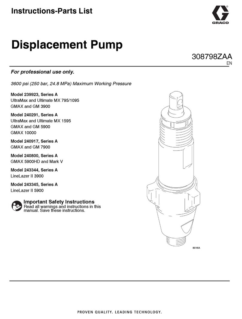
Remove the bung adapter (18) from the pump and
screw it tightly into the bung adapter plate (306). Lower
the pump (A) through the bung adapter. Tighten the
screw on the bung adapter to hold the pump steady.
Apply thread sealant and screw the suction tube
assembly (307) into the pump’s fluid intake valve.
Setup Procedure for all Models (Refer to
Figs. 2 or 3, as applicable)
System Accessories
Install an air line filter (D) in the main air line (E), to
remove harmful dirt and moisture from the compressor
air supplied to the pump and gun.
Near the pump’s fluid outlet, install a tee and drain
valve (G).
Hose and Gun Connections
The Hose Kit consists of the spray gun’s air and fluid
supply hoses. The fluid hose (401) has spring guards
on both ends, and includes an in-line fluid filter (402) at
the gun end. The hoses are tied together for ease of
movement.
Connect the male end of the air hose (403) to the 1/4
npsm(f) swivel adapter (509) at the outlet of the gun air
regulator (C), and connect the female end to the air
inlet in the spray gun (H) handle.
Connect the male end of the fluid hose (401) to the
pump’s fluid outlet, and connect the female end to the
gun’s fluid inlet. Do not install the spray tip in the gun
at this time.
