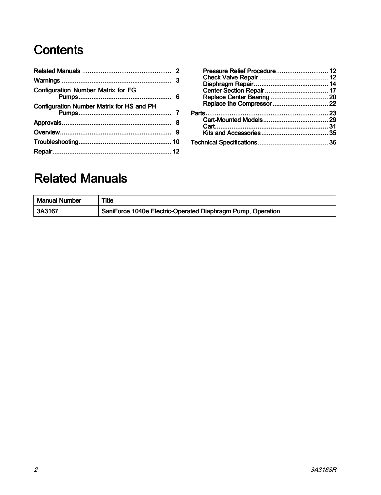
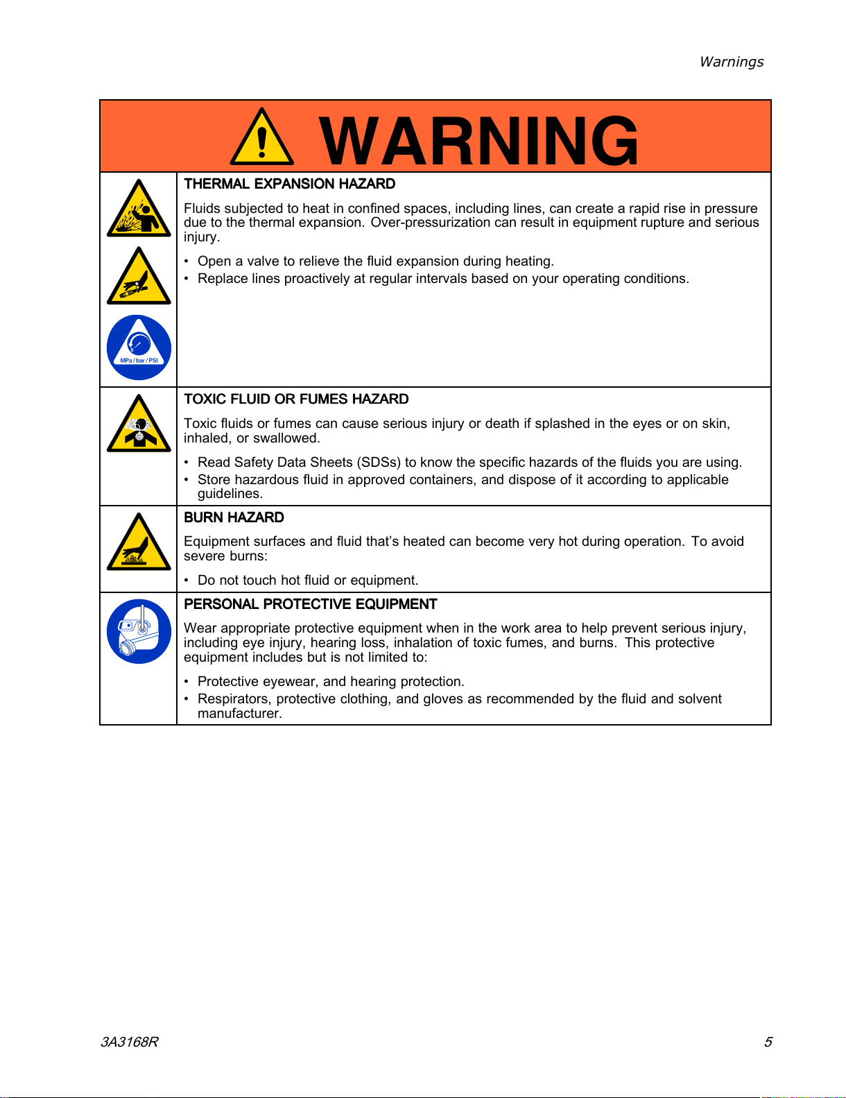
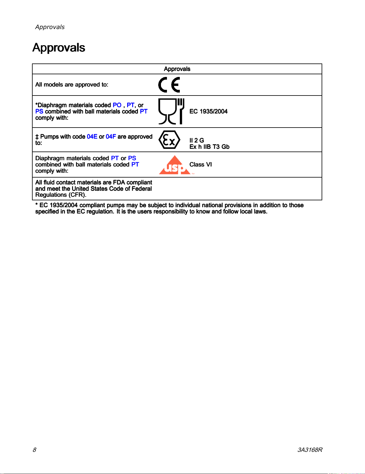
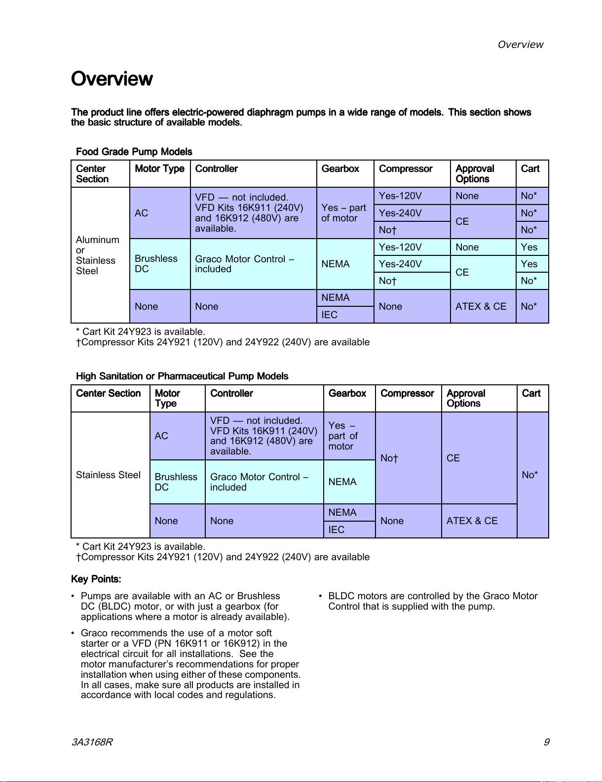
Graco SaniForce 1040e Use and care manual
Other Graco Water Pump manuals

Graco
Graco Husky 2150 Operation manual

Graco
Graco Husky 2150e Use and care manual

Graco
Graco VRM User manual

Graco
Graco EP2 User manual

Graco
Graco Dura-Flo A Series Operation manual

Graco
Graco 218334 User manual

Graco
Graco Injecto-Flo 26A485 User manual

Graco
Graco SaniForce 1590 HS Operation manual

Graco
Graco 225006 Operation manual

Graco
Graco E-Flo DC User manual

Graco
Graco 244195 Operating instructions

Graco
Graco 29:1 Lube Pro User manual

Graco
Graco 970056 Operation manual

Graco
Graco SoloTech ST6 Use and care manual

Graco
Graco 3A2977K Parts list manual

Graco
Graco 232-504 Operation manual

Graco
Graco Merkur A Series Parts list manual

Graco
Graco Fire-Ball J Series Operation manual

Graco
Graco 218-940 Operation manual

Graco
Graco Husky 1050HP Instruction Manual


Popular Water Pump manuals by other brands


Fieldmann
Fieldmann FVC 5015 EK user manual

Everbilt
Everbilt EFSUB5-122HD Use and care guide

esotec
esotec 101018 operating manual

Becker
Becker BASIC VASF 2.80/1-0.AC230 operating instructions

Sykes AmeriPumps
Sykes AmeriPumps GP100M Operation and maintenance instructions

DUROMAX
DUROMAX XP WX Series user manual

BRINKMANN PUMPS
BRINKMANN PUMPS SBF550 operating instructions

Franklin Electric
Franklin Electric IPS Installation & operation manual

Xylem
Xylem e-1532 Series instruction manual

Milton Roy
Milton Roy PRIMEROYAL instruction manual

STA-RITE
STA-RITE ST33APP owner's manual

GÜDE
GÜDE HWW 900 GC Translation of the original instructions