1-3
Spindl-Gard SG-1 and SG-2 Systems L42110
1.3.2.2 Controller. Several means of control are available for the
SG-1. Operation can be controlled by signals from user’s
machine control or by one of several controllers available
from Graco as follows:
WMP Maxi-Monitor• ®: This microprocessor-based
controller can be used to schedule and initiate lube
cycles on a machine cycle or time basis as well as
to relay fault conditions.
Solid-State Timer: This solid-state timer can be•
used to initiate lube cycles on a time basis. A
built-in memory retains the cycle time for 1-1/2
hours during power failure or machine shutdown to
resume from the point where it was suspended.
Flexi-Monitor: Utilizing the latest solid-state•
programmable control technology, the Flexi-Monitor
controls complex multiple-zone lubrication systems.
Not only does the Flexi-Monitor control lubrication
cycles, but it can monitor and report every aspect
of the lubrication system; including temperature,
vibration, fluid flow, pressure, and system operating
status.
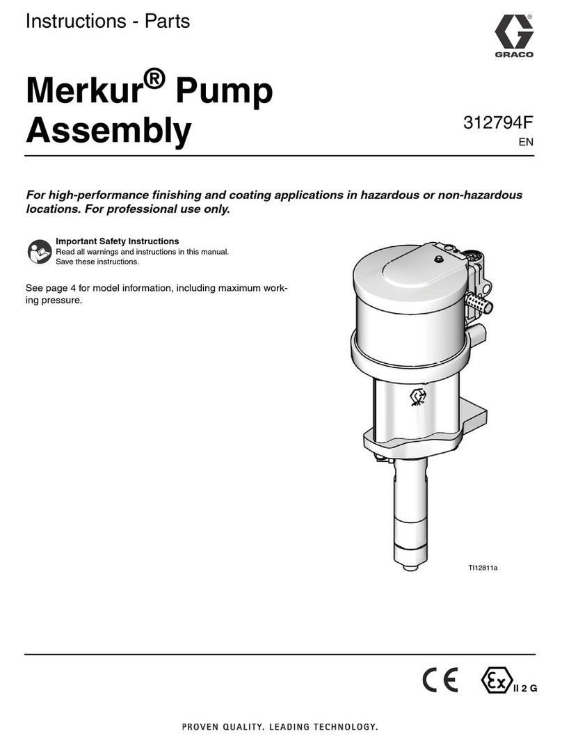
1.3.2.3 Pump Package. Several types of pump packages
are available to supply oil to the Spindl-Gard system.
Most applications use a Modu-Flo series pump
package equipped with a reservoir sized to the system
requirements. This series of pumps may either be
pneumatic- or hydraulic-powered and is available
in different lube output capabilities to fit the specific
requirements of each system.
1.3.2.4 Filter. A 10-micron filter placed in the outlet line of the
pump provides filtration of oil entering the system. A final
ten-micron oil filter at the divider valve inlet provides the
final filtration before oil enters the divider valve.
1.3.2.5 Divider Valve. This valve meters the precise amount of
oil required for each Spindl-Gard nozzle or terminating
lube point. The divider valve consists of stackable
sections, each of which can provide oil to one or two lube
points. The sections can be arranged to provide metered
oil to up to sixteen lube points. A valve section can be
supplied with a cycle indicator pin to provide visual
indication that the divider valve is cycling. The indicator
pin can also be used to actuate a cycle switch which
then provides a signal to the system controller.
1.3.2.6 Cycle Switch. The cycle switch is a limit switch which
is actuated by the movement of the cycle indicator pin.
If a blockage occurs in a lube line, the divider valve will
not cycle and the cycle switch will not be actuated. If
the switch is not actuated within a set time period, the
controller provides a warning signal.
1.3.2.7 Proximity Switch. The proximity switch is a proximity-
type sensor which is attached to the valve section of the
divider valve and senses the movement of the divider
valve piston during cycling. The proximity switch provides
a signal that is used to monitor the system in the same
manner as the cycle switch.
1.3.2.8 Spindl-Gard Spray Nozzle. The basic nozzle can be
installed in heads with walls up to 1-3/4 inches (44.4
mm) thick. It has separate 1/8 inch NPT inlet ports for air
and oil. Nozzle design and system air pressure (15 psi
(1 bar) at nozzle inlet) combine to provide a 60 degree
conical spray pattern.
1.3.2.9 Soft-Seat Check Valve. This valve, installed at the
bearing point, prevents oil drainage of the oil lines and
prevents air from entering the oil lines. An optional use
is installing the check valve at the lube inlet of the spray
nozzle.
1.3.2.10 2-psi Relief Valve. Installed at the lowest point of
the machining head gear cavity, this valve serves the
following functions:
It maintains a positive internal head pressure to•
prevent coolant and other contaminants from
entering the head.
By relieving at 2 psi, it prevents build-up of•
excessive pressure which could interfere with
proper oil dispersion.
It keeps the gear cavity dry by providing a simple•
means to drain off oil that would otherwise collect.
1.3.2.11 Pressure Switch. An optional 1-psi pressure switch
mounted to the machine head can be used to detect
changes in air pressure within the machining head cavity
due to broken air lines, clogged spray nozzles or worn
seals.
1.3.3 SG-1 Operation
NOTE: Refer to Figure 1-1 for item numbers referenced in the
descriptive paragraphs below.
1.3.3.1 The pump (1), and controller (3) are mounted on an
easily accessible part of the machine. The controller
energizes the pump at predetermined intervals to supply
lubricant to the system. The divider valve (7) with cycle
switch or proximity switch (4) supplies lubricant to either
spray nozzles or terminating lube points. The cycling of
the divider valve is monitored by the controller through
an electrical signal generated by either the cycle switch
or proximity switch. A pump failure, power failure, loss of
lubricant, plugged or crushed lube line, or broken supply
line would prevent the cycle switch or proximity switch
from producing the required signal to the controller,
which would register a fault condition.
1.3.3.2 The spray nozzle (9), supplied with constant clean dry
air (approximately 40 ºF (4.4 ºC) dewpoint, 5-micron
absolute filtration, at 15 psi (1 bar)), pressurizes the
machining head and supplies intermittent lube in the
form of a spray to the gears and bearings in the machine
head cavity. Air consumption is 0.6 scfm (17 sclm) per
nozzle. A relief valve (10) inserted at the lowest point
of each machining spindle cavity maintains positive air
pressure at 2 psi (0.14 bar). It also provides a simple
means to drain off any collected oil in the machine head


