DECALS
2.0
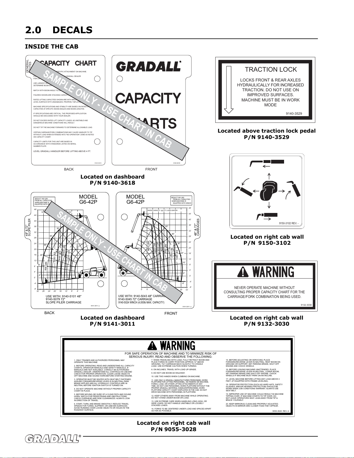
INSIDE THE CAB
TRACTION LOCK
9140-3529
LOCKS FRONT & REAR AXLES
HYDRAULICALLY FOR INCREASED
TRACTION DO NOT USE ON
IMPROVED SURFACES
MACHINE MUST BE IN WORK
MODE
9132-3030
NEVER OPERATE MACHINE WITHOUT
CONSULTING PROPER CAPACITY CHART FOR THE
CARRIAGE/FORK COMBINATION BEING USED
R
9140-3618
FRONT
GENERAL
NOTES
9140-3618
LEVEL GRADALL HANDLER BEFORE LIFTING ABOVE 4 FT
USE CAPACITY CHART FOR SPECIFIC ATTACHMENT ON MACHINE
FOR OTHER ATTACHMENTS CONSULT A GRADALL DEALER
FOR LOAD RATINGS NOT LISTED
USE LARGEST NUMBER VISIBLE FROM THE CAB TO
DETERMINE BOOM EXTENSION
MATCH WITH BOOM ANGLE TO DETERMINE ALLOWABLE LOAD
FIGURES SHOWN ARE STACKING CAPACITY TRUCK LEVEL
RATED LIFTING CAPACITIES SHOWN ARE WITH MACHINE ON A FIRM,
LEVEL SURFACE WITH UNDAMAGED, PROPERLY INFLATED TIRES
MACHINE SPECIFICATIONS AND STABILITY ARE BASED ON RATED LIFT
CAPACITIES AT SPECIFIC BOOM ANGLES AND BOOM LENGTHS
IF SPECIFICATIONS ARE CRITICAL, THE PROPOSED APPLICATION
SHOULD BE DISCUSSED WITH YOUR DEALER
DO NOT EXCEED RATED LIFT CAPACITY LOADS, AS UNSTABLE AND
DANGEROUS MACHINE CONDITIONS WILL RESULT
DO NOT TIP THE MACHINE FORWARD TO DETERMINE ALLOWABLE LOAD
CERTAIN CARRIAGE/FORK COMBINATIONS MAY CAUSE HANDLER TO TIP
WITHOUT LOAD WHEN EXTENDED INTO "NO OPERATION" ZONE AS NOTED
ON CAPACITY CHART
CAPACITY LIMITS FOR THIS UNIT ARE BASED IN
ACCORDANCE WITH STANDARDS LISTED ON SERIAL
NUMBER PLATE
BACK
SAMPLE ONLY - USE CHART IN CAB
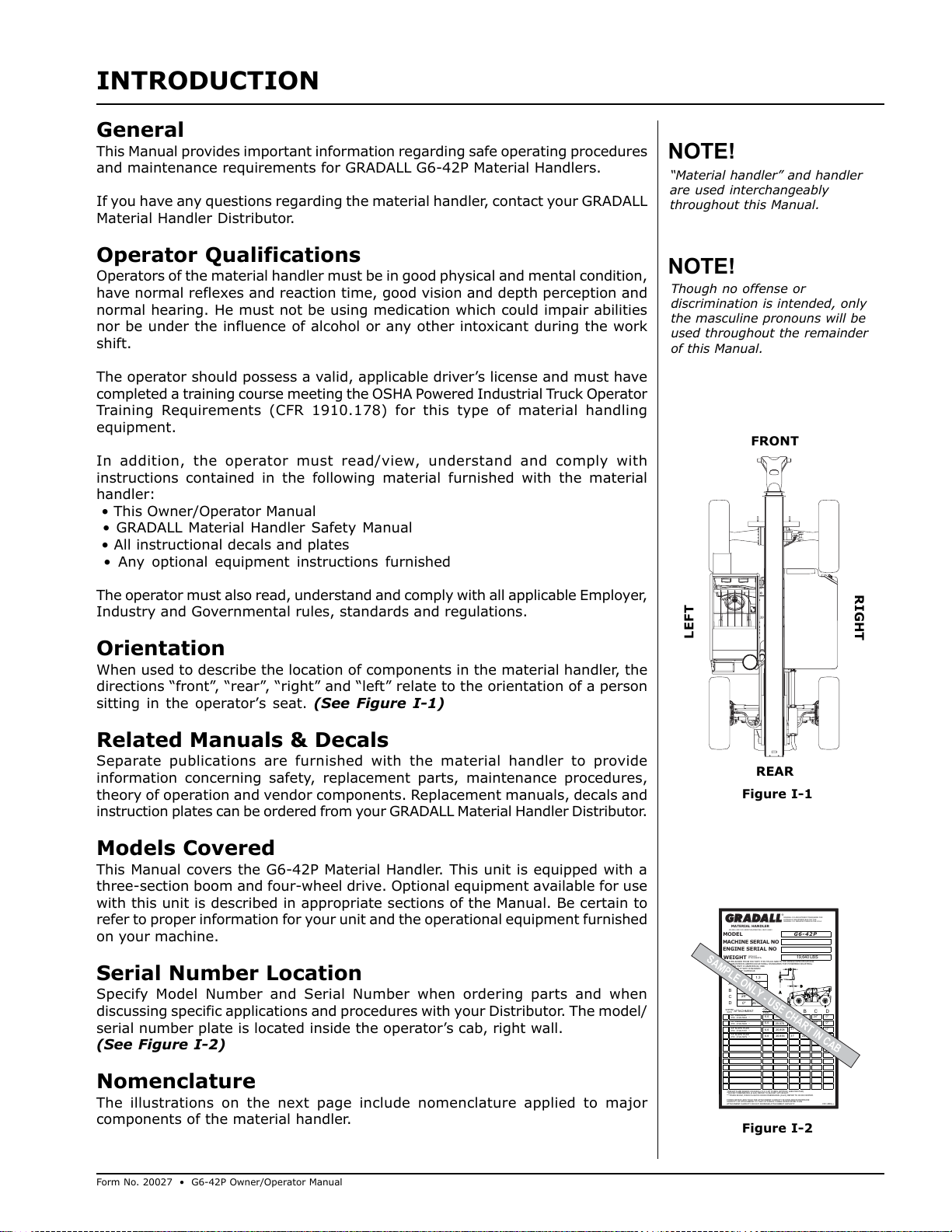
Located on dashboard
P/N 9140-3618
Located on dashboard
P/N 9141-3011
Located on right cab wall
P/N 9055-3028
Located on right cab wall
P/N 9150-3102
Located above traction lock pedal
P/N 9140-3529
Located on right cab wall
P/N 9132-3030
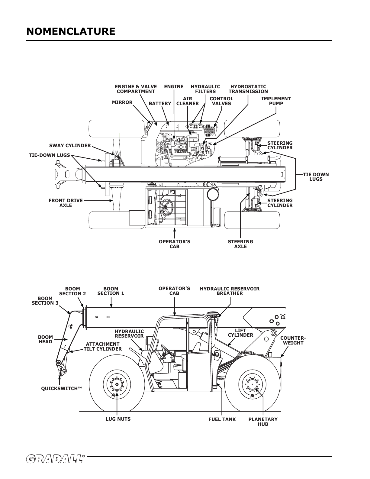
6000 LBS
USE WITH: 9140-5043 48" CARRIAGE
9140-5045 72" CARRIAGE
9140-5024 WINCH (4,000lb MAX CAPACITY)
9141-3011 (-)
FRONT
48" & 72"
CARRAIGES
MODEL
G6-42P
DEDUCT 350 LBS
FROM ALL CAPACITIES
WHEN MACHINE IS
EQUIPPED WITH WINCH
5000 LBS
4000 LBS
2000 LBS
3000 LBS
1300 LBS
RATED CAPACITY @ 2 FT LOAD CENTER
1
2
3
4
5
6
0'
-4'
-8'
4'
8'
12'
16'
20'
24'
28'
32'
36'
40'
44'
0' 4' 8' 12' 16' 20' 24' 28' 32'
48'
-9°
0°
10°
20°
30°
40°
50°
60°
70°
6600 LBS
48" & 72"
SLOPE PILER
9141-3011 (-)
BACK
DEDUCT 350 LBS
FROM ALL CAPACITIES
WHEN MACHINE IS
EQUIPPED WITH WINCH
MODEL
G6-42P
USE WITH: 9140-5101 48"
9140-5079 72"
SLOPE PILER CARRIAGE
1
2
3
4
5
6
5000 LBS
4000 LBS
2000 LBS
3000 LBS
900 LBS
RATED CAPACITY @ 2 FT LOAD CENTER
0'
0'
4'
8'
12'
16'
20'
24'
28'
32'
36'
40'
44'
-4'
-8'
4'8'
12'16'20'24'28'32'
48'
60°
70°
50°
40°
30°
20°
10°
0°
-9°
6600 LBS
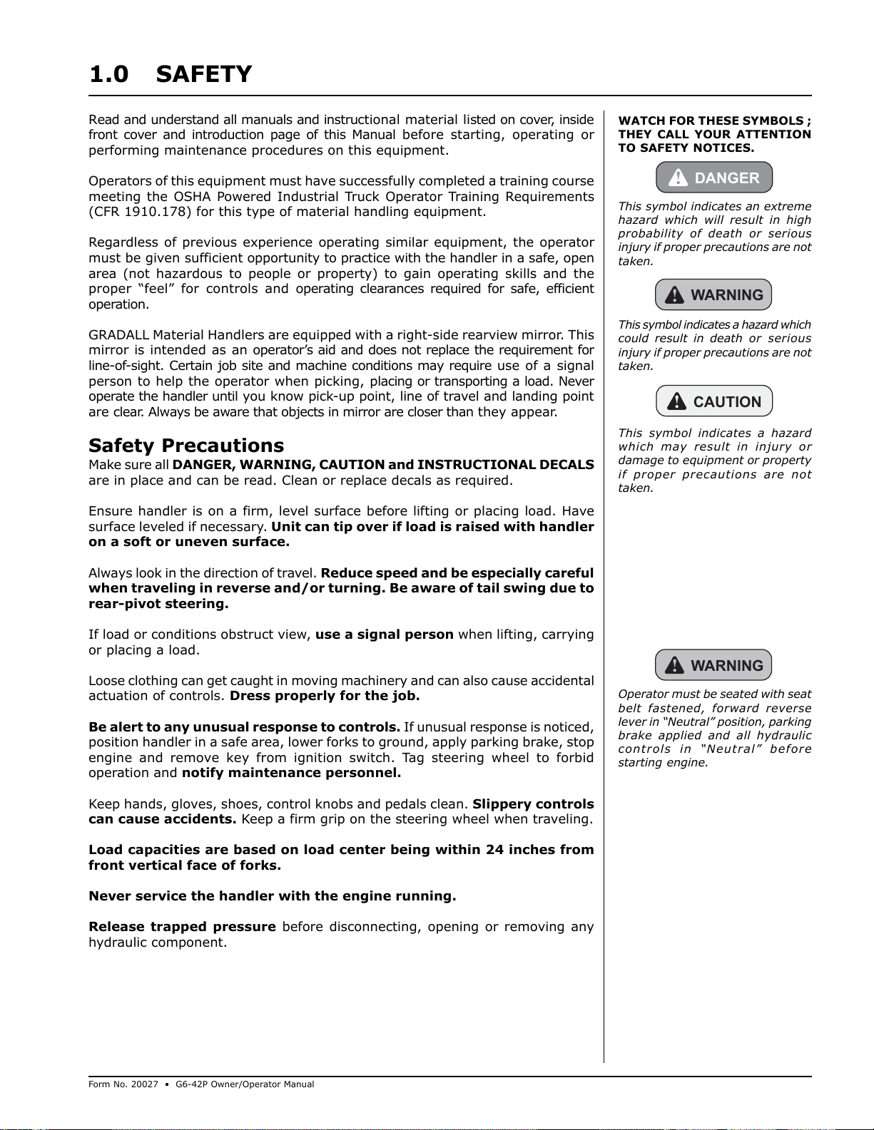
SAMPLE ONLY - USE CHART IN CAB
8 ON INCLINES, TRAVEL WITH LOAD UP-GRADE
9 DO NOT USE BOOM AS WALKWAY
10 USE TWO HANDS WHEN CLIMBING ON MACHINE
1 ONLY TRAINED AND AUTHORIZED PERSONNEL MAY
OPERATE THIS MACHINE
2 BEFORE OPERATING, READ AND UNDERSTAND ALL CAPACITY
CHARTS, OPERATOR MANUALS AND SAFETY MANUALS IF
MANUALS ARE NOT AVAILABLE, CONSULT AN AUTHORIZED
GRADALL DEALER UNDERSTAND ALL CONTROLS IN CAB AND
CHECK FOR PROPER OPERATION CLEAR LOOSE OBJECTS
OFF MACHINE AND SOUND HORN BEFORE STARTING ENGINE
3 OPERATOR MUST BE SEATED WITH SEAT BELT FASTENED
ASSURE FORWARD/REVERSE LEVER IS IN NEUTRAL,PARK
BRAKE APPLIED AND ALL HYDRAULIC CONTROLS ARE IN
NEUTRAL BEFORE IGNITION SWITCH IS TURNED ON
4 DO NOT OPERATE MACHINE WITHOUT PROPER CAPACITY
CHART IN PLACE
5 BEFORE MOVING, BE SURE OF A CLEAR PATH AND SOUND
HORN WATCH FOR PEDESTRIANS AND OBSTRUCTIONS
CHECK OVERHEAD AND SIDE CLEARANCES ALWAYS LOOK
IN DIRECTION OF TRAVEL
6 START, TURN, AND BRAKE SMOOTHLY REDUCE TRAVEL
SPEEDS FOR TURNS, SLIPPERY, OR UNEVEN SURFACES
AVOID RUNNING OVER LOOSE OBJECTS OR HOLES IN THE
ROADWAY SURFACE
7 WHEN TRAVELING WITH LOAD, FULLY RETRACT BOOM AND
PLACE FORKS IN CARRY POSITION (APPROX 12" ABOVE
GROUND) TILT CARRIAGE BACK SLIGHTLY TO CRADLE
LOAD USE EXTREME CAUTION WHEN TURNING
11 USE ONLY A GRADALL MANUFACTURED PERSONNEL WORK
PLATFORM FOR LIFTING PERSONNEL NO RIDERS ON MACHINE,
FORKS, LOAD, OR OTHER LIFTING ATTACHMENTS AT ANY
TIME DO NOT USE PERSONNEL WORK PLATFORM WITHOUT THE
PROPER GRADALL MATERIAL HANDLER/PERSONNEL WORK
PLATFORM CAPACITY CHART DISPLAYED IN THE CAB DO NOT
DRIVE MACHINE WITH PERSONNEL IN PLATFORM
12 KEEP OTHERS AWAY FROM MACHINE WHILE OPERATING
DO NOT STAND UNDER BOOM OR LOAD
13 USE EXTREME CARE WHEN HANDLING LONG, HIGH, OR
WIDE LOADS DO NOT HANDLE UNSTABLE OR LOOSELY
STACKED LOADS
14 FORKS TO BE CENTERED UNDER LOAD AND SPACED APART
AS FAR AS POSSIBLE
15 BEFORE ADJUSTING OR SERVICING, PLACE
FORWARD/REVERSE LEVER IN NEUTRAL, REST BOOM ON
GROUND OR SUPPORT, SET PARKING BRAKE, SHUT OFF
ENGINE AND CHOCK WHEELS
16 BEFORE LEAVING MACHINE UNATTENDED, PLACE
FORWARD/REVERSE LEVER IN NEUTRAL, LOWER BOOM,
SET PARKING BRAKE,AND SHUT-OFF ENGINE CHOCK
WHEELS IF MACHINE MUST PARK ON AN INCLINE
17 LEVEL MACHINE BEFORE LIFTING ANY LOAD ABOVE 4
FEET (IF EQUIPPED WITH FRAME LEVELING)
18 OPERATOR PROTECTION (SUCH AS HARD HATS, SAFETY
GLASSES, AND/OR HEARING PROTECTION) SHOULD BE
WORN WHEN JOB CONDITIONS WARRANT ALWAYS USE
SEAT BELT
19 IMPROPER USE OF MACHINE COULD RESULT IN MACHINE
TIPPING OVER IF MACHINE STARTS TO TIP OVER, DO
NOT LEAVE OPERATORS SEAT LEAN AWAY FROM TIP &
BRACE YOURSELF
20 KEEP MIRROR(S) CLEAN AND PROPERLY ADJUSTED
OBJECTS IN MIRROR ARE CLOSER THAN THEY APPEAR
9055-3028 REV A
FOR SAFE OPERATION OF MACHINE AND TO MINIMIZE RISK OF
SERIOUS INJURY, READ AND OBSERVE THE FOLLOWING:
9150-3102 REV -
Courtesy of Crane.Market