Graf Klaro Easy SBR User guide

1 / 54
Instructions for
start-up, operation and maintenance
Klaro Easy SBR wastewater
treatment system
Control unit version
KLbasic / KL24base
KLplus / KL24plus
General building authorities' ap-
proval:
In the Carat septic tank:
No.: Z-55.31-319
(discharge class C)
No.: Z-55.31-437
(discharge class D)
In the Carat XL septic tank:
No.: Z-55.31-319
(discharge class C)
No.: Z-55.31-435
(discharge class D)
Be sure to read before starting
up!
Contents
1. GENERAL 4
2. SAFETY NOTICES 6
3. SCOPE OF SUPPLY 9
4. FUNCTION OF THE SBR SYSTEM 11
5. CONTROL AND MACHINE CABINET 14
6. THE SMALL WASTEWATER TREATMENT SYSTEM'S
CONTROL UNIT 19
7. ADDITIONAL FUNCTION OF THE KLPLUS/KL24PLUS
AND KLBASIC/KL24BASE CONTROL UNIT 30
8. OPERATION AND MAINTENANCE 38
9. FAULT MESSAGES AND RECTIFICATION 42
10. OPERATING INSTRUCTIONS 46
11. ANNEX I: TEMPLATE FOR WEEKLY / MONTHLY
CHECK NOTES 49
12. MAINTENANCE LOG FOR KLARO SMALL
WASTEWATER TREATMENT SYSTEMS 52

2 / 54
WARRANTY
CERTIFICATE
Otto Graf GmbH
Kunststofferzeugnisse
Dear Sir/Madam,
Congratulations on purchasing a quality product from Otto Graf GmbH. We hereby confirm
that your small wastewater treatment system is covered by warranty for
3 years
The warranty only applies to the wastewater treatment technology. Accessories and addi-
tional options are not covered by the warranty. Within the warranty period, Otto Graf GmbH
shall replace materials free of charge. No other services are covered by the warranty.
Conditions of warranty
The warranty applies if the following requirements are met:
1. The wastewater treatment system must be installed and started up by a specialist.
Companies certified by the DWA or trained by Otto Graf GmbH are considered spe-
cialists.
2. Maintenance must be undertaken by a specialist company as described in the oper-
ating manual and the approval. If claims for warranty are submitted, all maintenance
logs must be provided if requested.
3. Wearing parts are not covered by the warranty, nor are defects and damage for
which we are not responsible and which are the result of improper system operation,
failure to undertake maintenance, faults caused by the customer and unauthorised
changes to the system.
4. Follow-on costs resulting from replacing the unit, shutting down the system etc. are
not covered by the warranty.
Statutory warranty claims are not affected by this warranty and remain in place in their en-
tirety.
Teningen, April 2015
Otto Graf GmbH
Carl-Zeiss-Str. 2-6
DE-79331 Teningen

3 / 54
Dear Sir/Madam,
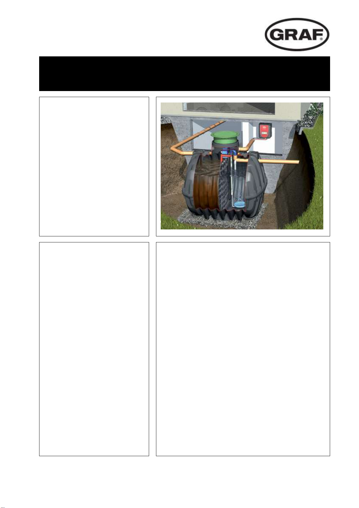
We are delighted that you have chosen to buy a modern Klaro Easy SBR system. Klaro Easy
is a quality product that as a complete system meets the requirements of DIN EN 12566-3 and
DIN 4261-1, making it a fully biological small wastewater treatment system. Below you will find
some important information for safely operating your system for a long time to come.
The SBR system is designed to receive all domestic wastewater. Other wastewater, e.g.
from restaurants and / or commercial premises etc., may only be received if this was
specified and taken into account in the system's design.
Biocides, toxic substances or substances which are not biocompatible must not enter
this system because they hinder bacteria important to wastewater cleaning and cause
problems in the biological process (detailed information is provided on the following pag-
es).
To meet official cleaning requirements, it is essential that the system is operated
in accordance with our operating and maintenance instructions. You will find these
instructions on the following pages.
We also ask you to read the following information carefully:
The internal control cabinet must be installed in a dry, well ventilated room (cellar or
garage).
External control cabinets should be located as much in the shade as possible to prevent
them from overheating in the summer.
At all times ensure that the cabinet, especially its ventilation apertures, are not covered
and are freely accessible for maintenance work.
EPP control cabinet: Ventilation apertures on the front and top
Internal control cabinet: Ventilation apertures on the sides
External control cabinet: Ventilation apertures on the rear
The power supply must be ensured at all times. Please ensure that the fuse on the con-
trol cabinet is sufficient (16 A). Additional electrical fixtures on the same fuse may dis-
rupt operation.
Otto Graf GmbH in Teningen

1. General
4 / 54
1. General
Details about your system1.1
In case you have any queries while operating the system, please enter the details of your sys-
tem here as follows. Should you encounter a fault, these details will enable our staff to find a
remedy faster.
You will find the details on the type plate fitted to the outside of internal cabinets and the inside
of external cabinets.

1. General
5 / 54
Original EC declaration of conformity for small wastewater system in plastic tank1.2
Manufacturer: Otto Graf GmbH Kunststofferzeugnisse
Carl-Zeiss-Str. 2-6
DE-79331 Teningen
Tel. +49 7641 589-0
Fax +49 7641 589-50
www.graf.info
hereby declares that the KLARO Easy,small wastewater system in plastic tanks for 4 to 50
inhabitants meets the requirements of the following directives:
2011/305/EC "Regulation no. 305/2011 of the European Parliament and of the Council
of 9 March 2011 on defining harmonised conditions for marketing con-
struction products".
2006/42/EC "Directive of the European Parliament and of the Council of 17 May 2006
on machines and changes to Directive 95/16/EC".
2006/95/EC "Directive of the European Parliament and of the Council of 12 Decem-
ber 2006 on the harmonisation of the laws of Member States relating to
electrical equipment designed for use within certain voltage limits".
2004/108/EC "Directive of the European Parliament and of the Council of 15 Decem-
ber 2004 on the approximation of the laws of the Member States relating
to electromagnetic compatibility and repealing Directive 89/336/EEC".
The following harmonised standards were applied:
EN 12566-3:2005+A2:2013 "Small wastewater treatment systems for up to 50 PT Part 3:
Packaged and/or site assembled domestic wastewater treatment
plants."
EN 60204-1/A1: 2009 "Electrical equipment of machines. Part 1: General require-
ments."
EN 13849-1: 2008 "Safety of machinery –Safety-related parts of control systems. –
Part 1: General principles for design."
This EC declaration of conformity ceases to apply if the product is modified without consent.
Responsible for documentation: Otto Graf GmbH
Teningen, 31.03.15
Arne Schröder
(Product management team leader)

2. Safety notices
6 / 54
2. Safety notices
This chapter contains details relating to safety measures and residual risks. Read this chapter
through carefully before using the system to ensure that it is used as safely as possible.
Explanation of warning notices and prohibitions2.1
Warning of danger
Warning of dangerous voltage
Warning of tripping risk
Warning of hot surface
Warning of hand injuries
Warning of explosive atmospheres
Fire, naked flames and smoking prohibited
Danger notices2.2
1. To ensure safety, everyone who comes into direct contact with the system must note the
content of this documentation.
2. The system must not be used for any purpose other than that described by the manufactur-
er.
3. Local operating and safety requirements and legislation must be followed at all times, even
if not explicitly mentioned in these instructions. The same applies to environmental require-
ments.
4. If the operator becomes aware of mistakes or dangers, the manufacturer or responsible
maintenance company must be informed immediately.

2. Safety notices
7 / 54
5. Safety precautions must never be removed or bypassed during normal operation of the ma-
chine. Safety precautions may only be temporarily bypassed or deactivated by the mainte-
nance fitter during repairs and maintenance.
6. When working with chemical substances, contact with the chemicals should be avoided as
far as possible. Before these substances may be used, the instructions for use on the pack-
aging must be read and followed.
7. If the use of personal protective equipment (safety shoes, protective glasses, gloves, ear
defenders, etc.) is prescribed, ensure that they are used. Defective or damaged protective
equipment must be immediately replaced with fully functional equipment.
8. Work on electrical equipment may only be undertaken by specialists.
9. All safety and danger notices on the machine should always be kept fully legible.
10. Hot parts must not come into contact with explosive or highly flammable chemicals.
11. Do not put vessels containing liquids on electric switch cabinets; short circuits may occur if
the liquid is spilled.
12. The system must not be operated by anyone under the influence of alcohol (remember that
alcohol may still remain in the body the day after consumption!) or medication which limits
cognitive ability or ability to react.
13. The system must be de-energised before any maintenance or cleaning work.
14. Other than for maintenance purposes, the system should always be left switched on, other-
wise correct wastewater cleaning cannot be guaranteed.

2. Safety notices
8 / 54
Warning notices2.3
Installation location
Ensure that the machine cabinet is not installed above or in the direct
vicinity of water vessels. Risk of electric shock if improperly installed.
Mains connection
Only connect the machine cabinet to a correctly installed 230 V socket or
earth cable which is fused with an upstream 16 A fuse as specified in the
technical data.
Electrical equipment connected to the mains may be damaged during a
storm. We would recommend fitting surge protection in the building to
protect against this. The connection cable must be laid such that it does
not represent a tripping hazard.
Explosive atmos-
pheres
The control unit must not be fitted or activated in environments with po-
tential explosive atmospheres or in places where there are flammable
materials. Sparks in such environments may cause an explosion or fire
and this may result in physical injuries or even death.
Interferences
The control unit may cause medical equipment to malfunction. This de-
vice should therefore not be used in close proximity to medical equip-
ment.
Damage
The control unit must not be operated if the housing or cable insulation is
damaged or crushed.
Service work
Service work on the machine cabinet may only be undertaken by author-
ised specialists / electricians.
Voltage supply
The power supply must be ensured at all times. Please ensure that the
fuse on the control cabinet is sufficient (16 A). Additional electrical fix-
tures on the same fuse may disrupt operation.

3. Scope of supply
9 / 54
3. Scope of supply
The wastewater treatment system basically comprises the septic tank with wastewater treat-
ment technology setting-up kit and control cabinet. These main parts are connected to one an-
other using air hoses laid in the ground.
The septic tank(s) is(are) split into two areas, the sludge reservoir and buffer in the inlet area
and the SBR reactor in the outlet area. In a one-tank system, these two stages are housed in
one tank and separated by a partition. In a multi-tank system, the sludge reservoir buffer and bio
reactor each have their own tank. A feed lifter is present in the sludge reservoir in the form of a
mammoth pump with its own air supply.
In the sludge reservoir / buffer you will find:
feed lifter in the form of a mammoth pump with its own air supply (marked in red)
In the bio reactor you will find:
stainless steel air distributor system with membrane pipes or aerator plates
feed lifter in the form of a mammoth pump with its own air supply (marked in red)
stainless steel air supply system with EPDM membrane, finely perforated
outflow lifter in the form of a mammoth pump with its own air supply (marked in black)
secondary sludge lifter in the form of a mammoth pump with its own air supply (marked
in white)
integrated sampling points (only in one- and two-tank systems!)
In the control cabinet for mounting on indoor walls or in the control column for outdoor installa-
tion you will find:
a quiet, low-maintenance air compressor
a valve unit
a control unit which conforms to the requirements of BGV A3 and DIN EN 60204-1
As an option, the system can be fitted with an integrated sampling facility from which a water
sample can be taken.

3. Scope of supply
10 / 54
One-tank system in the Carat septic tank3.1
Two-tank system in the Carat tank3.2
One-reservoir system in a TWIN underground tank3.3
Schlamm-
speicher/
Puffer
SBR-
Reaktor
L
Hs Hp
HWges
E
H
H BB,min
H BB,max
A
E
140-340
Sludge
storage/
buffer
SBR-
reactor
Sludge storage/ buffer
SBR-reactor
sludge return

4. Function of the SBR system
11 / 54
4. Function of the SBR system
The Klaro Easy is a fully biological small wastewater treatment system, which functions on the
principle of the SBR process (aeration system in retention process). The system basically com-
prises 2 stages: A sludge reservoir with integrated upstream buffer and activated sludge stage
in closed retention mode (SBR reactor).
The upstream sludge reservoir with integrated buffer fulfils the following functions:
storage of primary and secondary sludge
retention of deposited materials and floating solids
storage of supply water
compensation of fluctuations in the wastewater supply related to volume and concentration.
The wastewater treatment system is operated using a microprocessor control, which controls
the air compressor and air distribution for the various lifters via solenoid valves / stepped mo-
tors.
Systems for breaking down the organic matter present in the water (removal of4.1 carbon: discharge class C)
The process is a series of 5 steps undertaken in turn and repeated several times a day (usu-
ally 4 times).
Step 1: Feed
The raw wastewater held in the sludge reservoir is fed to the SBR reactor via an air lift
pump. This is arranged such that only water free of solids is pumped. The special design of
the lifter guarantees a minimum water level in the sludge reservoir.
Step 2: Aeration
In this step, the wastewater is aerated and mixed. Membrane pipe or plate aerators fitted on
the base of the chamber aerate the wastewater.
The system's aeration equipment is supplied with ambient air by a control cabinet installed
separately. An air compressor produces the compressed air needed. Aeration usually takes
place intermittently
with two simultaneous outcomes:
the microorganisms in the activated sludge are supplied with oxygen, which is needed
for their metabolism and therefore for the pollutants to be broken down
there is intensive contact between the wastewater and bacteria.

4. Function of the SBR system
12 / 54
Step 3: Settling phase
This step is a rest phase in which no aeration takes place. The activated sludge settles with
gravity (sedimentation phase). A clear water zone forms at the top and a sludge layer at the
bottom. Any floating sludge is on top of the clear water zone.
Step 4: Clear water extraction
In this phase, the biologically cleaned waste water (clear water) is drawn out of the SBR
stage. It is pumped out by an air lift (or mammoth) pump, which uses compressed air. The
air lift pump is designed such that any floating sludge present at the layer of clear water is
not pumped out and a minimum water level is retained in the SBR stage without further
components.
Step 5: Removal of excess sludge
In this phase, excess activated sludge is pumped by an air lift pump from the SBR reactor
chamber to the sludge reservoir chamber, where it is stored. This excess sludge is pumped
out of the base of the SBR chamber.
Once the 5th step is complete, the cleaning process starts again with step 1.
The cycle described above is usually undertaken four times a day. The switching times and
number of cycles can be adapted following discussion with the manufacturer. They may only be
adapted by an authorised maintenance specialist.
The system can also be manually switched to holiday mode.
When in holiday mode, system operation is greatly reduced during long periods without a supply
of wastewater.

4. Function of the SBR system
13 / 54
Systems with extra nitrogen elimination (discharge class D)4.2
Nitrogen is also removed biologically using certain strains of microorganisms. In systems which
are also designed for additional denitrification, a short burst of aeration is undertaken at the start
of the aeration phase to circulate the water and stimulate denitrifying bacteria which convert
nitrate into elementary nitrogen.
Systems with extra phosphate elimination (discharge class D+P)4.3
Phosphate precipitation results from the addition of polyaluminium chloride in the SBR reactor.
The phosphate precipitation equipment includes a removable support platform in the dome (ac-
cessory, art. no. 107362). The precipitant canister is located on this platform. Alternatively, the
precipitant canister can be positioned separately near the switch cabinet. There is a metering
pump in the system's switch cabinet, which pumps the precipitant out of the precipitant canister
and into the SBR reactor. The precipitant is added during the reactor's feed phase. The amount
of precipitant needed can be set on the metering pump. Mixing takes place during the aeration
phase. The precipitant forms an insoluble compound with the phosphate, which settles in the
tank.
Details of how to start up and operate the pump can be found under Item 6.
Systems with extra hygiene (discharge class D+H)4.4
The extra Klaro UV module removes germs from the biologically cleaned wastewater using ul-
traviolet light (UV), which kills microorganisms within a matter of seconds, leaving no residue or
harmful by-products.
Separate instructions are available explaining how to install and start up the UV module.

5. Control and machine cabinet
14 / 54
5. Control and machine cabinet
All the system's mechanical and electrical components are installed in a switch cabinet. The
cabinet for internal installation is made from expanded polypropylene (EPP; used for
wastewater treatment systems for 4-10 inhabitants) or is a powder-coated metal cabinet (used
for wastewater treatment systems for 11 or more inhabitants).
For installation out of doors, the components are fitted in a plastic cabinet. The cabinet contains
both the control unit and all machine elements needed. It is opened using the key provided.
Technical setup5.1
The main components of the machine unit are:
quiet air compressor
valve unit with 4 solenoid valves / stepped motors for distributing the air for aeration and
lifting using air lift pumps (feed, discharge, sludge return)
control unit for automatic mode with preset operating cycles
cooling fan (only in systems with a rotary valve blower)
phosphate precipitant pump (optional)
GPRS communication module (optional)
The elements of the control unit visible from the outside are:
keypad for operating the control unit
two-row LCD for displaying operating statuses and fault messages
1 LED (operating check) for visually displaying operation (green/red)
Machine cabinet5.2
The internal switch cabinets may only be installed in dry, dust-free and well ventilated rooms
(cellar, technical room or garage). There must be a 230 V socket (16A, slow blow) near the cab-
inet. Additional electrical fixtures on the same fuse may disrupt operation.
The cabinets should be freely accessible at all times; in particular the ventilation apertures
should always be uncovered.

5. Control and machine cabinet
15 / 54
The electrical connection of the switch cabinet must only be carried out by a
qualified electrician.
EPP switch cabinet for indoor installation (380 x 580 x 300 mm)
The EPP machine cabinet is secured to a wall with the hanger bolts
supplied. The hanger bolts should be secured to the wall horizontally
using dowels spaced 280 mm apart. The cabinet is then affixed to them
and secured with wing nuts.
When choosing where to install the cabinet, note that the hose connec-
tions are on the underside of the cabinet.
Metal cabinet for indoor installation (500 x 500 x 300 mm)
The machine cabinet is prepared for mounting on the wall. The wall
brackets provided must be attached to the rear of the cabinet first.
There must be a 230 V socket (16A, slow blow) near the cabinet.
The mains supply with a main switch and ventilation grille are located
on the right-hand side. The hose connections and another ventilation
grille can be found on the right.
Large systems for more than 40 inhabitants are supplied with a two-door cabinet for installing on
the ground.
Systems for 75 or more inhabitants, running on a 3-phase current of 380 V, must be connected
by an electrician as shown in the terminal diagram provided. Be sure that the compressor is
rotating in the right direction.
Fuse con-
nections!

5. Control and machine cabinet
16 / 54
Plastic column for outdoor installation
The plastic column intended for installation out of doors
should be sunk into the ground up to the mark on the front of
the cabinet (see installation instructions). A ditch of a suffi-
cient depth should be dug.
In order to replace the ventilation grille on the rear of the col-
umn, there must be a free space of at least 10 cm around the
grille. The location should be cool and protected from direct
sunlight during the summer months. If shading is provided on
site, this should be designed with open sides so that the col-
umn is sufficiently ventilated and in order to avoid trapped
heat.
The outdoor column should be sunk into the soil up to the
mark. Finally the ditch should be filled correctly such that the
column is stable, firm and stands upright in the soil.
To reduce earth moisture, we recommend filling the space
inside the base with a thin layer of cement screed or base
filling granulate (accessory, art. no. 107607). If this is not
done, the electric parts may be damaged by corrosion if
the soil is very damp.
Main components:
1. Maintenance switch
2. Control unit
3. Strip of valves with 4 solenoid valves / stepped motors
4. Air compressor
5. Cabinet fan on rear of cabinet
6. Socket
Caution: When doing anything other than operating the control unit, the maintenance switch
should be turned to the "0" position!
An underground cable is laid to supply power to the cabinet. This is connected to socket (6) in
the switch cabinet. To disconnect from the mains, a mains disconnector must be fitted on
site as close as possible to the switch cabinet between the fuse and switch cabinet. Ensure
that the mains disconnector is always easily accessible for maintenance and repairs!

5. Control and machine cabinet
17 / 54
A cabinet made from facing concrete is needed for a compressor size of DT 4.16 or more. This
requires a concrete foundation (foundation plan available from GRAF).
Figure 1: Inside of two-door concrete cabinet
Figure 2: Two-door concrete cabinet
When starting up the system (i.e. once assembly is complete), all chambers should be filled up
to the bottom edge of the discharge if this hasn't been done already.
Caution: Because the sludge reservoir and SBR reactor do not communicate with one another,
they must be filled individually.
Starting up the cabinet5.3
Once the system has been connected to the power supply, it performs a quick self-test (if the
control cabinet has a main switch, it should be in position "1"). This test takes a few seconds,
then the system automatically enters normal operation (automatic). During the self-test the
words "SYSTEM TEST ... OK", the program version and the control unit's serial number are
displayed briefly. The system's current operating mode is then displayed in the liquid crystal
display. If a battery has not yet been placed in the control unit and the time and date have not
yet been set, the control unit will display fault messages. These can be acknowledged using the
Esc key. The time and date can then be set via the menu (see below).
The function of the control unit, three lifters, aeration and if present the cabinet fan should then
be checked. This can be done via the Manual operation menu item in the control unit.
Please note: The lifters will only work if the tanks are filled.
If the time and date are not set correctly, operating faults are saved with the
wrong times.
The system should be reset to automatic mode once the test is completed successfully.

5. Control and machine cabinet
18 / 54
System response to disconnection from the voltage supply5.4
If the system is disconnected from the mains (e.g. due to a power cut), the control program and
the operating hours counted are retained in the system control's memory. An intermittent warn-
ing tone sounds. This warning tone only sounds after a delay of several seconds (see Item 10.3,
Power cut detector). When the power supply to the system is restored, it automatically restarts
as described above, provided that there is a sufficiently charged battery in the control unit.
Important information:
If the system is disconnected from the mains for more than 24 hours, the system will be unable
to clean the wastewater properly if at all.

6. The small wastewater treatment system's control unit
19 / 54
6. The small wastewater treatment system's control unit
The system is operated using the control unit in the cabinet door (or inside the cabinet with out-
door cabinets). The control unit allows operating parameters to be set, operating statuses to be
displayed, system parameters to be queried and operating times to be programmed by a spe-
cialist.
You can change the display contrast in automatic mode by pressing the ESC and arrow buttons
at the same time.
The figures below show the setup of the operating units.
KLbasic/KL24base control unit
KLplus/KL24plus control unit
Figure 3: View of the KLbasic / KL24base operating
unit
Figure 4: View of the KLplus / KL24plus operat-
ing unit
Operating status display
The system's operating status is indicated by the LED (Green = Operation / Red = Fault) and
by text on the LC screen.
In normal operating mode (aeration mode), the liquid crystal display looks like this:
Figure 5: View of liquid crystal display during aeration phase
In automatic mode, the liquid crystal display shows the current operating phase and time re-
maining in this stage of operation.
Should a fault occur, a message appears in the liquid crystal display indicating which compo-
nent is faulty (e.g. compressor fault).
Note: Item 9 describes in more detail how the system behaves in the event of a fault.
Aeration
120.10 m
aeration
rest: 120.10 MIN

6. The small wastewater treatment system's control unit
20 / 54
KLbasic/KL24base control unit
KLplus/KL24plus control unit
The following operating phases are displayed:
KLbasic /
KL24base display
Process undertaken
KLplus /
KL24plus display
Charchng
Valve 1 is activated, the feed lifter pumps the
wastewater to be cleaned from the sludge res-
ervoir into the bio reactor.
charging
Denitrif
Valve 2 is intermittently activated, the activated
sludge is briefly mixed with the wastewater.
There are long pauses in between (reaction
times).
denitrification
Aeration
Valve 2 is activated, the bio reactor is aerated at
intervals.
aeration
Sediment
No valves are activated, the activated sludge
settles in the bio reactor.
sedimentation
Discharc
Valve 1 is activated, the wastewater is pumped
into the discharge.
discharching
SludgeRe
Valve 4 is activated, the excess sludge is
pumped from the reactor into the sludge reser-
voir.
sludge return
Pause
Valve 2 is activated, the bio reactor is aerated at
intervals (considerably less than in the "aera-
tion" phase).
cyclepause
Vacation
Valve 2 is activated, the bio reactor is aerated at
intervals, no cleaning cycles are undertaken.
vacation oper.
XX.XX m
Display showing time remaining.
rest: XXX.XX min
The control unit is operated using the keypad.
Figure 6: View of operating panel
Table of contents
Popular Ultrasonic Jewelry Cleaner manuals by other brands

Mi-T-M
Mi-T-M AW-7020-8002 Operation instructions

Kärcher
Kärcher A Plus SC21 Operation instruction and parts list manual

ELICTO
ELICTO ES-530 user guide

Spear & Jackson
Spear & Jackson S21CPW Original instruction manual

Lyman
Lyman Turbo Sonic 6000 operating instructions

Hornady
Hornady Lock-N-Load Sonic Cleaner 2L instruction manual