manuals.online logo
Brands
  1. Home
  2. •
  3. Brands
  4. •
  5. Graff
  6. •
  7. Plumbing Product
  8. •
  9. Graff b-collection 5127510 Operator's manual

Graff b-collection 5127510 Operator's manual

Instructions for assembly and use •Montage- und Gebrauchsanweisung •Notice technique montage et utilisation •Manuale di Montaggio e Uso •Instrucción de Montaje y Servicio
by
IOG 5128.51 Rev. 1 February 2015
1
BRAUSEBATTERIE•BATTERIEDEDOUCHE
MEZCLADORDEDUCHA•BATTERIADOCCIA
SHOWER MIXER
5127510 (PC)
5127540 (PC)
150mm
150mm
150mm
150mm
B-SMART
4
4
90mm
90mm
5129510 (PC)
5129540 (PC)
150mm
150mm
150mm
150mm
B-PURE
4
4
100mm
100mm
5128510 (PC)
B-SOFT
4
150mm
104mm
150mm
5128540 (PC)
4
104mm
Instructions for assembly and use •Montage- und Gebrauchsanweisung •Notice technique montage et utilisation •Manuale di Montaggio e Uso •Instrucción de Montaje y Servicio
by
IOG 5128.51 Rev. 1 February 2015
2
BRAUSEBATTERIE•BATTERIEDEDOUCHE
MEZCLADORDEDUCHA•BATTERIADOCCIA
SHOWER MIXER
For assembly you will need: Bei der Montagewerden Les outils nécessaires pour Para el montaje se Per il montaggio sono
an adjustable spanner benötigt: le montage: necesitan: necessari i seguenti utensili:
pliers, verstellbarer Schlüssel, La clef à ouver llave ajustable, chiave registrabile,
teflon tape, Kombizange, La pince universelle, alicates universales, tenaglia piana,
silicon or other sealant. Teflonband, La bande Téflon, cinta de teflón, nastro di teflon,
Silikon oder anderes Le silicone ou une autre silicona u otro tipo de silicone o altro tipo di
garniture d'étanchéité. material de estancar guarnizione.





E
IT
F
BEFOREINSTALLATION:
Read the instruction before assembly.
Read all the notes and information on the use and maintenance of the unit.
Before installing the unit it is advisable to rinse it out to remove any impurities or dirt.
For the hot and cold water supply we recommend you install stops with filters.




AVANTDE PROCÉDERÀ L'INSTALLATION:
Avant installation, veuillez lire la notice.
Prenez connaissance de toutes les informations et remarques liées à l'usage et à l'entretien de la batterie
de douche.
Avant d'installer la batterie, il est recommandé d'effectuer un rinçage de l'installation, de manière à éliminer
les impuretés éventuelles.
Nous vous recommandons d'installer des robinets à tournant sphérique au niveau de l'alimentation en eau
chaude et en eau froide.




ANTESDEINSTALAR:
Antes de empezar el montaje lea la instrucción.
Lea todos los comentarios, informaciones sobre el servizio y la conservación de la batería.
Antes de instalar la batería se recomienda enjuagar la instalación para quitar toda la basura.
En la alimentación de agua caliente y fría recomendamos el montaje de grifos angulares de bolas con el
filtro.




VORDERMONTAGE:
Bevor Sie mit der Montage beginnen, lesen Sie bitte dieAnleitung.
Lesen sie bitte alle Bemerkungen, Informatio-nen über.
Bevor Sie die Batterie montieren, ist angebracht die Anlage zu spülen, um die Verunreinigungen zu
beseitigen.
Wir empfehlenauf dem Warm- und Kaltwasser-zulaufdie Kugelhähne mit Filterzu montieren.




PRIMADELMONTAGGIO:
Prima del montaggio leggi il manuale.
Leggi tutte le avvertenze, le informazioni sul funzionamento e sulla manutenzione della batteria.
Prima di montare la batteria è opportuno sciacquare l'impianto allo scopo di eliminare le impurità.
Sull'alimentazione con acqua calda e fredda consigliamo di montare rubinetti a sfera con il filtro.




GB D
GB
D
F E IT
1
2
3
4
5
A
Decorative cover with
sealant
Lever
Fixing screw
Switch knob
Plug
Allen (hex) key
Zierkappe mit Abdichtung
Hebel
Befestigungsblechschraube
Schalterknopf
Blindplatte
Innensechskantschlüssel
Cache décoratif avec étanchéité
Levier
Vis de fixation
Bouton de réglage du commutateur
Obturateur
Clef Allen
Protección decorativa con
Hellado
Palanca
Tornillo sujetador
Botón del conmutador
Obturador
Llave Allen
Protezione decorativa con
guarnizione
Leva
Vite di fissaggio
Pomolo del deviatore
Tappo
Chiave a brugola
1
12
145
3
A
2
5
3.1
A
3
5
2
Instructions for assembly and use •Montage- und Gebrauchsanweisung •Notice technique montage et utilisation •Manuale di Montaggio e Uso •Instrucción de Montaje y Servicio
by
IOG 5128.51 Rev. 1 February 2015
3
BRAUSEBATTERIE•BATTERIEDEDOUCHE
MEZCLADORDEDUCHA•BATTERIADOCCIA
SHOWER MIXER
3.2
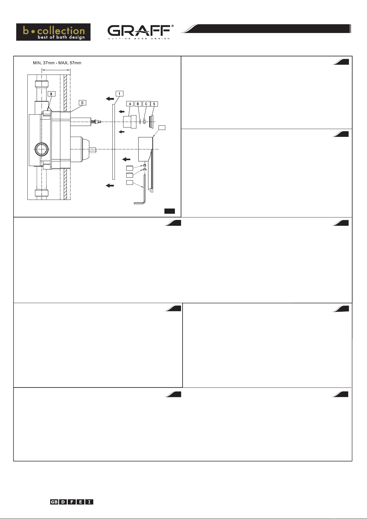
ZIERSCHUTZUNDSCHALTHEBELMONTIEREN– S. Abb. 3.1 - 3.2
1) Nach dem Abschluss der Arbeiten mit der Ausbauwand sind die loszuschrauben und
die Montageblende (E) zu beseitigen.
2) Falls die Montageblende (D) über die Oberfläche der Ausbauwand hinausragt, ist die vorsichtig mit
einem scharfen Werkzeug abzuschneiden.
3) Die Mutter (C) losschrauben und die Scheibe (B) vom Bolzen des Ventilschalters abnehmen.
4) Auf das Ventil (R) die Zierblende (1) samt Dichtung aufsetzen. Die Zierblende vorsichtig an die Wand
heranschieben und richtig positionieren.
5) Drehknopf (4) und U-Scheibe (B) auf Schalterbolzen aufsetzen und Mutter (C) schrauben. Danach
Blindplatte (5) einsetzen.
6) Hebel (2) auf Wassermischerbolzen aufsetzen und Befestigungsblechschraube (3), (5) mit
beigelegtem Innensechskantschlüssel (A)festschrauben.
Wird die Zierkappe und der Hebel auf dem Ventil ohne Schalter montiert, Schritte 3 und 5 ignorieren.
D
INSTALLING THE DECORATIVE SHIELDANDLEVER– see fig. 3.1 - 3.2
1) Afterfinishingtheworkswiththe finishing wall, removetheinstallation cover (E).
2) Iftheinstallationcover(D) projects overthewallface,carefully cutitoffusing asharptool.
3) Unscrew the nut (C) and take off the washer (B) fromthevalveswitchspindle.
4) Slide the decorative cover (1) with the sealing on the valve (R). Carefully push it to the wall and set
into thecorrectposition.
5) Put the switch knob (4) on the valve switch mandrel then put the washer (B) and fix the nut (C). After
tightening the nut fix the plug (5).
6) Put the lever (2) on the mixer mandrel and screw the fixing bolt (3), (5) with the enclosed Allen key (A).
Skip steps 3 and 5 if installing the decorative shield and lever on a switchless valve.
GB
MONTAGGIO DELLAPROTEZIONE DECORATIVAE DELLALEVA – vedi fig. 3.1-3.2
1) Dopo aver finito i lavori con la parete di finitura togli la protezione di montaggio (E).
2) Nel caso in qui la protezione di montaggio (D) sporgesse dal livello della parete di finitura tagliala
attentamente con un utensile tagliente.
3) Svita il dado (C) e togli la rondella (B) dallo stello del deviatore della valvola.
MONTAJE DE LAPROTECCIÓN DECORATIVAYLAPALANCA – ver fig. 3.1-3.2
1) Una vez terminados los trabajos en la pared de acabado, quite la tapa de montaje
2) Si la tapa de montaje (D)
(E).
sobresale la superficie de la pared de acabado, córtela con cuidado usando
una herramienta aguda.
3) Desenrosque la tuerca (C) y quite la arandela (B) del vástago del desviador de la válvula.
INSTALLATION DU CACHE DÉCORATIF ET DU LEVIER – schémas 3.1 - 3.2
1) Après avoir terminé les travaux sur la paroi de finition enlevez le cache de fixation (E).
2) Si le cache de fixation (D) dépasse le nu de la paroi de finition coupez-le avec précaution à l'aide d'un
outil pointu.
3) Retirez l'écrou (C) et enlevez la rondelle (B) de la tige du sélecteur de vanne.
4) Placez le cache décoratif (1) avec le joint sur la vanne (R). Appuyez le cache avec précaution contre le
mur et possitionez-le correctement.
5) Placez le bouton de réglage sur la tige de la vanne (4), puis la rondelle (B), avant de visser l'écrou (C).
Après avoir vissé l'écrou (C) mettez l'obturateur (5).
6) Placez le levier sur la tige du mitigeur (2) et vissez jusqu'au bout l'écrou de fixation (3),(5) à l'aide de la
clef Allen (A) jointe au kit de montage.
Si vous montez le cache décoratif et le levier sur une vanne sans commutateur, veuillez ne pas prendre en
compte les points 3 et 5.
FE
IT
4) Infila la valvola (R) la protezione decorativa (1) insieme alla guarnizione. Spingila, facendo attenzione,
contro la parete e disponi in posizione adeguata.
5) Sullo stelo del deviatore della valvola metti il pomolo (4), poi la rondella (B) e avvita il dado (C). Dopo
aver serrato il dado (C) metti il tappo (5).
6) Metti la leva sullo stelo del miscelatore (2) e serra la vite di fissaggio(3), (5) con la chiave a brugola
(A)
aggiunta al set.
In caso di montaggio della protezione decorativa e della leva su una valvola priva di deviatore, ometti i passi
3 e 5.
4) En la válvula (R) meta la tapa decorativa (1) con el sellado. Con cuidado acérquela a la pared y ponga
en la posición correcta.
5) En el mandril del conmutador de la válvula meta el botón (4), a continuación la arandela (B) y aprieta
la tuerca (C). Una vez apretada la tuerca (C) ponga la obturador (5).
6) En el mandril del mezclador meta la palanca (2) y enrosque el tornillo sujetador (3), (5) con la llave
allen (A)adjunto al juego.
Para el montaje de la protección decorativa y la palanca en la válvula sin conmutador, evite los pasos 3 y 5.
OPERATING
Lifting the lever upwards opens and controls the water flow volume.
Lowering the lever will shut the water flow off.
Turning the lever anti-clockwise will increase the water temperature while turning in the opposite
direction will lower the water temperature. An extreme left position provides only hot water, an extreme
right position only cold water.
The switch valve changes operating modes: pressing the knob will direct the water to the shower head
while pulling it will direct the water either to the tap or other receiver (e.g. shower handset).
The knob automatically returns to the initial position (directing the water flow to the spout) when the
water flow is shut down.



BEDIENUNG
Durch das Ausschwenken des Handgriffes nach oben wird der Wasserauslauf geöffnet sowie die
Wasserausgabe stufenlos geregelt. Wird der Handgriff zurückgeschwenkt, wird der Wasserauslauf
geschlossen.
Die Wassertemperatur wird durch das Drehen des Handgriffes gegen den Uhrzeigersinn erhöht und im
Uhrzeigersinn gesenkt. In der linken Handgriff-Anschlaglage wird nur das Warmwasser, in der rechten
Handgriff-Anschlaglage wird nur das Kaltwasser gezapft.
Das Umschaltventil ist für die Betriebsmoduswahl bestimmt: wird der Umschalterknopf gedrückt, läuft
das Wasser aus dem Brausekopf; wird der Umschalterknopf gezogen, läuft das Wasser aus der
Mischbatterie (oder aus einer anderen Zapfstelle, bspw. aus dem Handduschkopf).
Nachdem der Wasserauslauf geschlossen ist, kehrt der Umschalterknopf automatisch in die
Ausgangslage zurück (der Wasserstrom wird zum Mischbatterieauslauf geleitet).



UTILISATION
L'ouverture de l'eau et le libre réglage de son écoulement se fait lorsque vous placez la manette vers le
haut. Pour arrêter l'écoulement de l'eau, il suffit de placer la manette vers le bas.
Pour augmenter la température de l'eau, il suffit de tourner la manette vers la gauche ; pour la réduire, de la
tourner vers la droite. Si vous placez la manette en position extrême à gauche, seule de l'eau chaude
s'écoulera. De la même manière, en position extrême à droite, seule de l'eau froide s'écoulera de la batterie.
Le commutateur sert à changer le mode de fonctionnement: en appuyant sur le bouton du commutateur,
l'eau sort par la tête de douche; en la tirant, l'eau sort du robinet (ou par tout autre sortie prévue, par
exemple une pomme de douche).
Après avoir coupé l'eau, le bouton se remet automatiquement en position initiale (sortie d'eau par le
robinet).



GB
DF
A
3
5
2
Instructions for assembly and use •Montage- und Gebrauchsanweisung •Notice technique montage et utilisation •Manuale di Montaggio e Uso •Instrucción de Montaje y Servicio
by
IOG 5128.51 Rev. 1 February 2015
4
BRAUSEBATTERIE•BATTERIEDEDOUCHE
MEZCLADORDEDUCHA•BATTERIADOCCIA
SHOWER MIXER
FUNZIONAMENTO
L'apertura del getto d'acqua e la regolazione scorrevole della sua portata avviene in seguito al
posizionamento della maniglia in alto. L'abbassamento della maniglia chiude il getto d'acqua.
L'aumento della temperatura dell'acqua avviene in seguito alla rotazione della maniglia a sinistra, e la
diminuzione in seguito alla rotazione della maniglia a destra. Il posizionamento della maniglia estremamente
a sinistra genera solo il getto di acqua calda, estremamente a destra solo il getto di acqua fredda.
La valvola di deviazione è prevista per la scelta del modo di lavoro: premendo il pomolo del deviatore il
getto d'acqua avviene tramite la testa della doccia, tirando il pomolo del deviatore il getto d'acqua
avviene tramite la bocca (o altro ricevitore, p. es.: doccetta).
Dopo la chiusura del getto d'acqua il pomolo del deviatore ritorna automaticamente alla posizione
iniziale (il getto d'acqua è direzionato sulla bocca).



MANEJO
La apertura de la salida del agua y el ajuste fluido de su flujo ocurre al mover el mango hacia arriba.
Bajar el mango causa el cierre del flujo de agua.
El aumento de la temperatura del agua ocurre al girar el mango a la izquierda, y la reducción al girar el
mango a la derecha. La posición extrema izquierda permite la salida sólo del agua caliente, la extrema
derecha la salida sólo del agua fría.
La válvula conmutadora sirve para escoger el modo de trabajo: presionar el botón del conmutador
causa la salida del agua por el cabezal de ducha, tirar el botón del conmutador causa la salida del agua
por el caño (u otro receptor, por ejemplo, el auricular de ducha).
Tras cerrar la salida de agua, el botón del conmutador vuelve automáticamente a la posición origen (la
salida del agua por el caño).



EIT

This manual suits for next models

5

Other Graff Plumbing Product manuals

Graff 2196300 Operator's manual

Graff

Graff 2196300 Operator's manual

Graff PESARO 1500-C3 User manual

Graff

Graff PESARO 1500-C3 User manual

Graff 8550 User manual

Graff

Graff 8550 User manual

Graff CUISINE E-9935 Operator's manual

Graff

Graff CUISINE E-9935 Operator's manual

Graff E-8527 Operator's manual

Graff

Graff E-8527 Operator's manual

Graff G-8006 User manual

Graff

Graff G-8006 User manual

Graff LUNA 5363400 User manual

Graff

Graff LUNA 5363400 User manual

Graff SENTO 5115000 Operator's manual

Graff

Graff SENTO 5115000 Operator's manual

Graff PRESCOTT Operator's manual

Graff

Graff PRESCOTT Operator's manual

Graff 6765 User manual

Graff

Graff 6765 User manual

Graff G-8078-T Series User manual

Graff

Graff G-8078-T Series User manual

Graff ELEGANTE Operator's manual

Graff

Graff ELEGANTE Operator's manual

Graff G-11210-LM55B User manual

Graff

Graff G-11210-LM55B User manual

Graff CANTERBURY 2386000 Operator's manual

Graff

Graff CANTERBURY 2386000 Operator's manual

Graff G-8232 User manual

Graff

Graff G-8232 User manual

Graff G-6800-LM47 User manual

Graff

Graff G-6800-LM47 User manual

Graff BLACKSTONE Series User manual

Graff

Graff BLACKSTONE Series User manual

Graff EX-3785 Operator's manual

Graff

Graff EX-3785 Operator's manual

Graff GN-11400 Series User manual

Graff

Graff GN-11400 Series User manual

Graff 1130-LM2 T Series User manual

Graff

Graff 1130-LM2 T Series User manual

Graff 2363490 Operator's manual

Graff

Graff 2363490 Operator's manual

Graff TARGA 2309000 Operator's manual

Graff

Graff TARGA 2309000 Operator's manual

Graff TERRA G-6710-LM46B User manual

Graff

Graff TERRA G-6710-LM46B User manual

Graff 7090 User manual

Graff

Graff 7090 User manual

Popular Plumbing Product manuals by other brands

Rejuvenation ELKTON Assembly instructions

Rejuvenation

Rejuvenation ELKTON Assembly instructions

Glacier bay 874-0101 Installation and care guide

Glacier bay

Glacier bay 874-0101 Installation and care guide

Columbia Products Sani-Lav 5A4A operating manual

Columbia Products

Columbia Products Sani-Lav 5A4A operating manual

Bradley S19-210FW Installation

Bradley

Bradley S19-210FW Installation

T.P.I. Handels RL 125 FH Instructions for use

T.P.I. Handels

T.P.I. Handels RL 125 FH Instructions for use

brondell CleanSpa CSA-35 installation instructions

brondell

brondell CleanSpa CSA-35 installation instructions

Elkay Elumina EG2522 Specifications

Elkay

Elkay Elumina EG2522 Specifications

Axor 40511000 Specification sheet

Axor

Axor 40511000 Specification sheet

Grohe Atrio 32652001 installation instructions

Grohe

Grohe Atrio 32652001 installation instructions

Franke SHHE0004 Installation and operating instructions

Franke

Franke SHHE0004 Installation and operating instructions

Pfister Zanna F-529-7ZN3 Quick installation guide

Pfister

Pfister Zanna F-529-7ZN3 Quick installation guide

Hans Grohe Metris Classic Series Instructions for use

Hans Grohe

Hans Grohe Metris Classic Series Instructions for use

Kohler TAUT 73194T-4E2 installation instructions

Kohler

Kohler TAUT 73194T-4E2 installation instructions

Hans Grohe Croma Showerpipe 27159000 manual

Hans Grohe

Hans Grohe Croma Showerpipe 27159000 manual

Hans Grohe Metris S 31023 Series Instructions for use/assembly instructions

Hans Grohe

Hans Grohe Metris S 31023 Series Instructions for use/assembly instructions

Brizo Venuto 64970LF manual

Brizo

Brizo Venuto 64970LF manual

Krowne Royal Series installation manual

Krowne

Krowne Royal Series installation manual

Bradley S45-1964 Installation

Bradley

Bradley S45-1964 Installation

manuals.online logo
manuals.online logoBrands
  • About & Mission
  • Contact us
  • Privacy Policy
  • Terms and Conditions

Copyright 2025 Manuals.Online. All Rights Reserved.