GRAIGAR YK-2005TM User manual

3 in 1, Type K/J, Pt 100 ohm, Infrared Thermomete
r
Real time data logger, 16000 Data logger no., RS232
THERMOMETE
R
Model : YK-2005TM

TABLE OF CONTENTS
1. FEATURES................................................................1
2. SPECIFICATIONS......................................................2
2-1 General Specifications..........................................2
2-2 Electrical Specifications........................................4
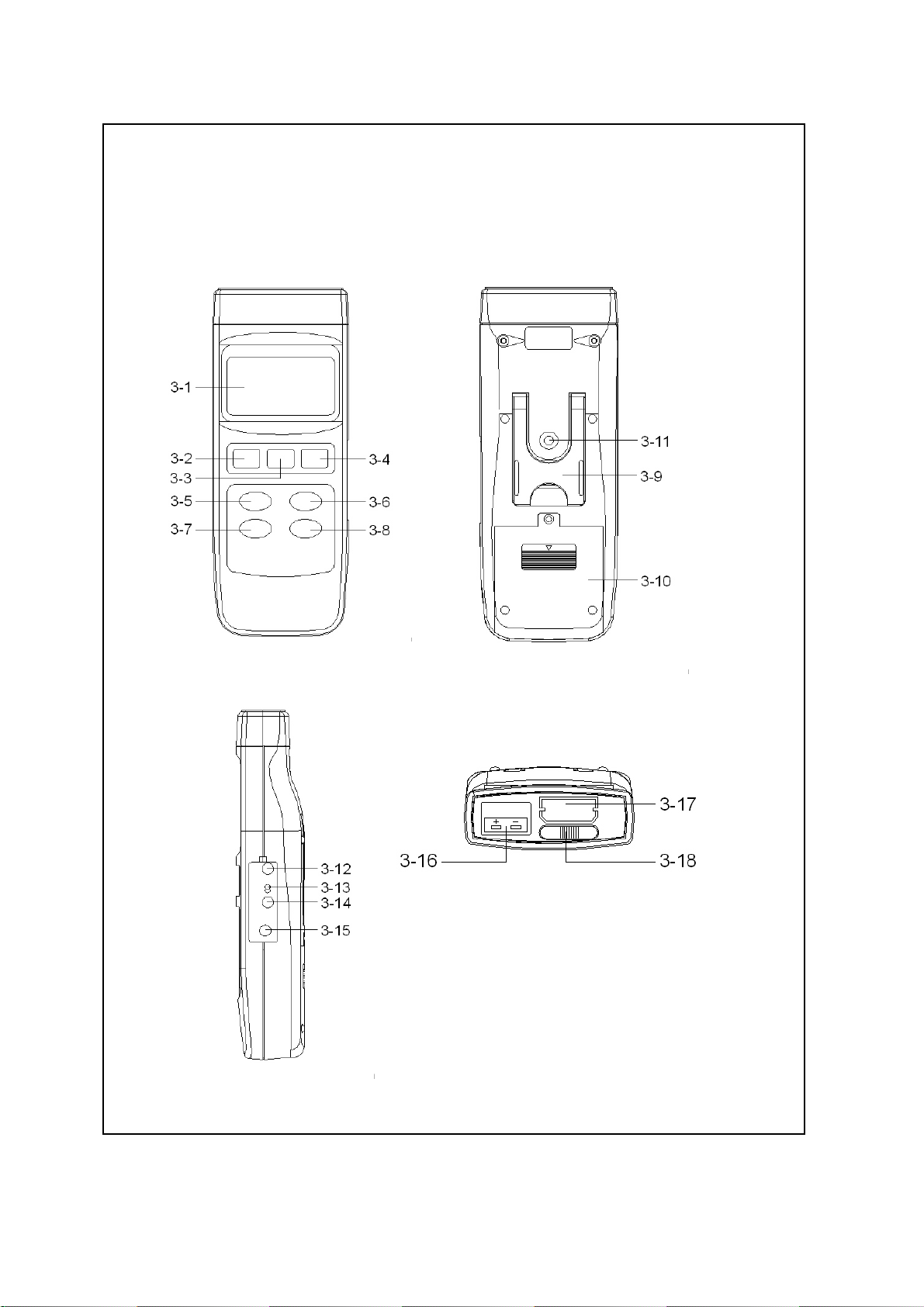
3. FRONT PANEL DESCRIPTION.....................................6
4. GENERAL MEASURING PROCEDURE...........................8
4-1 Thermocouple ( Type K/J ) Thermometer
Measurement......................................................8
4-2 Pt 100 ohm Measurement.................................... 9
4-3 Infrared Thermometer Measurement....................
.
9
4-4 Data Hold...........................................................
.
10
4-5 Data Record (Max., Min. reading).........................10
4-6 Data Logger........................................................11
5. ADVANCED ADJUSTMENT PROCEDURE...................... 13
5-1 Check Memory Space..........................................
.
14
5-2 Clear Memory......................................................15
5-3 Date/Time Setting...............................................
.
15
5-4 Sample Time Setting............................................15
5-5 Auto Power Off Default Setting.............................16
5-6 Temp. Unit Default Setting...................................16
5-7 Escape from the SETTING function.......................16
6. HOW TO SEND THE DATA OUT FROM THE METER.....
.
17
7. RS232 PC SERIAL INTERFACE...................................
.
20
8. BATTERY REPLACEMENT...........................................22
9. Type K/J OFFSET ADJUSTMENT.................................22
10. SYSTEM RESET.......................................................24
11. OPTIONAL ACCESSORIES........................................25

1. FEATURES
* 3 in 1, Thermocouple ( Type K/J ) thermometer,
Pt 100 ohm thermometer + Infrared thermometer.
* 0.1 degree resolution for Pt 100 ohm & type K/J.
* Wide temperature measuring range.
* 4 wires PT 100 ohm probe input, 0.00385 alpha
coefficient, meet DIN IEC 751, high precision.
* Offset adjustment.
* Fast humidity measuring response time.
* Real time data logger, build in clock ( hour-min.-sec.,
year-month-date ).
* Auto or manual data record, 16,000 Data logger no.
* Wide sampling time adjustment range from two
seconds to 8 hours 59 minutes 59 seconds.
* RS232 computer interface.
* Can default auto power off or manual power off.
* Multi function with easy operation
* Large LCD with multiple display.
* Data hold, record max. and min. reading.
* Microcomputer circuit provides special function & offer
high accuracy.
* Power by UM3 ( 1.5 V ) x 4 batteries or DC 9V adapter.
* RS232 PC serial interface.
* Separate probe, easy for operation of different
measurement environment.
1

2. SPECIFICATIONS
2-1 General Specifications
Circuit Custom one-chip of microprocessor LSI
circuit.
Display LCD size : 58 mm x 34 mm.
Measurement 1. Thermocouple probe
@ Thermocouple type K
@ Thermocouple type J
2. Platinum Pt 100 ohm
( 0.00385 alpha coefficient,
meet DIN IEC 751 )
3. Infrared Thermometer
Display Unit , .℃℉
Resolution 0.1 , 0.1 .℃℉
Sampling Time Manual Push the data logger button
of Data Logger once will save data one time.
@
Set the sampling time to
0 second
Auto 2 sec to 8 hour 59 min. 59 sec.
Temperature Automatic temp. compensation for the
Compensation type K/J thermometer and Infrared
Thermometer.
Linear Both for Type K/J. Pt 100 ohm and
Compensation the IR thermometer.
Offset Available to adjust the zero drift value,
Adjustment adjustment by pushing button.
Probe Input Type K/J probe :
Socket Standard 2 pin thermocouple socket.
Pt 100 and IR probe :
Exclusive socket.
2

Over Indication
Show " ".
Data Hold Freeze the display reading.
Memory Recall Maximum & Minimum value.
Sampling Time Approx. 1 second.
of display
Power off Auto shut off saves battery life or
manual off by push button.
Data Output RS 232 PC serial interface.
Operating 0 to 50 .℃
Temperature
Operating Less than 80% R.H.
Humidity
Power Supply DC 1,5 V battery ( UM3 ) x 4 PCs,
* main instrument
( Heavy duty type ).
DC 9V adapter input.
@ AC/DC power adapter is optional.
Power Supply DC 3V silver battery.
* clock module
Type : CR2032.
Power Current Approx. DC 21.5 mA
@ Main instrument.+ Type K/J ( Pt 100 ) probe
Weight 515 g/ 1.13 LB.
@ Battery is included.
Dimension 2000 x 762 x 368 mm
Accessories Instruction manual.....................
.
1 PC
Included Type K probe, TP-01...................1 PC
DC 3V silver battery, CR2032......
.
1 PC
Carrying case.............................
.
1 PC
3

Optional * Type K thermocouple probe.
Accessories TP-02A. TP-03, TP-04
* Pt 100 ohm probe, PT-100P
* Infrared Probe, YK-200PIR
* AC to DC 9V adapter.
* RS232 cable, UPCB-02.
* Data Acquisition software,
SW-U801-WIN.
* Data Logger software, SW-DL2005.
2-2 Electrical Specifications (23±5 )℃
Type K/J thermometer
Sensor Reso- Range Accuracy
Type lution
Type K 0.1 ℃-50.0 to 1300.0 ℃± ( 0.2 % + 0.5 )℃
-50.1 to -100.0 ℃± ( 0.2 % + 1 )℃
0.1 ℉-58.0 to 2372.0 ℉± ( 0.2 % + 1 )℉
-58.1 to -148.0 ℉± ( 0.2 % + 1.8 )℉
Type J 0.1 ℃-100.0 to 1100.0 ℃± ( 0.2 % + 0.5 )℃
-50.1 to -100.0 ℃± ( 0.2 % + 1 )℃
0.1 ℉-58.0 to 2012.0 ℉± ( 0.2 % + 1 )℉
-58.1 to -148.0 ℉± ( 0.2 % + 1.8 )℉
* Accuracy value is specified for the meter only.
* Type K probe, TP-01 is the standard accessory.
* Other Type K probe. TP-02A, TP-03. TP-04 is the
optional accessory, refer page 25.
4

Platinum PT 100 ohm Thermometer
Resolution Range Accuracy
0.1 ℃-200.0 to 850.0 ℃± ( 0.2 % + 0.5 )℃
0.1 ℉-328.0 to 1562.0 ℉± ( 0.2 % + 1.0 )℉
Remark :
a.Accuracy value is specified for the meter only.
b.Linearity Correction :
Memorize the Pt 100 ohm's curve into the intelligent
CPU circuit.
c. Pt 100 probe input, 0.00385 alpha coefficient, meet
DIN IEC 751.
d.4 wires Pt 100 ohm probe ( Model : PT-100P ) is
optional, refer page 25.
Infrared Thermometer
Measurement -10 to 300 / 14 to 572 .℃℃℉℉
Range
Resolution/ 1 or 1 .℃℉
Accuracy ± 3 % of reading or ± 3 which ever is℃
greater.
* It should cooperate the optional
IR probe, YK-200PIR.
* Meter operating Temp. within 23± 5℃
& the emissivity value of measurement
target is 0.95.
* Spec. tested under the 20 cm dia.
black body, the measuring distance
from the Probe sensing Head is 30 cm.
@ Above specification tests under the environment RF Field
Strength less than 3 V/M & frequency less than 30 MHz only.
5

3. FRONT PANEL DESCRIPTION
6

3-1 Display
3-2 Power Button
3-3 HOLD Button ( ESC Button )
3-4 REC Button ( Enter Button )
3-5 Up Button▲
3-6 Function Button ( Down Button )▼
3-7 Send Button ( Clock Button )
3-8 SET Button ( Logger Button )
3-9 Stand
3-10 Battery Compartment/Cover
3-11 Tripod Fix Nut
3-12 LCD Brightness Adjust VR
3-13 System Reset Switch
3-14 RS-232 Output Terminal
3-15 DC 9V Power Adapter Input Socket
3-16 Type K/J Probe Input Socket
3-17 Probe Input Socket
3-18 Probe Lock Switch ( System On/Off Switch )
3-19 Probe Plug
3-20 Pt 100 ohm Probe ( optional )
3-21 IR ( Infrared Thermometer ) Probe ( optional )
7

4. GENERAL MEASURING
PROCEDURE
4-1 Thermocouple ( Type K/J ) Thermometer
Measurement
Attention :
It should not connect any probe into the
Probe Input Socket " ( 3-17, Fig. 1 ) and slide
Probe Lock Switch " ( 3-18, Fig. 1 ) to the On
position ( right position ).
1)Plug the Thermocouple Temp. Probe ( Type K Temp.
probe pr Type J Temp. probe, optional ) into " Type
K/J Probe Input Socket " ( 3-16, Fig. 1 )
2)Power on the meter by pressing the " Power Button "
( 3-2, Fig. 1 ).
3)For the Type K Probe, press the " Function Button "
( 3-6, Fig. 1 ) to let the bottom right LCD show the
" K type " indicator
For the Type J Probe, press the " Function Button "
( 3-6, Fig. 1 ) to let the bottom right LCD show the
" J type " indicator
Remark :
The specification of included Type K probe ( TP-01 )
* Max. short-tern operating temperature :
300 ( 572 ).℃℉
* It is an ultra fast response naked-bead
thermocouple suitable for many general purpose
application. 8

4-2 Pt 100 ohm Measurement
1)Install the " Pt 100 ohm Probe's Plug " ( 3-19, Fig. 1 )
into the " Probe Input Socket " ( 3-17, Fig. 1 ).
Attention :
After install the " Probe Plug ", should slide
Probe Lock Switch " ( 3-18, Fig. 1 ) to the On
position ( right position ).
2)Power on the meter by pressing the " Power Button "
( 3-2, Fig. 1 ). The bottom right LCD will show the
indicator " PT100 ", now the meter is ready for
the Pt 100 ohm Measurement.
4-3 Infrared Thermometer Measurement
1)Install the " Probe Plug " ( 3-19, Fig. 1 ) into the
" Probe Input Socket " ( 3-17, Fig. 1 ).
Attention :
After install the " Probe Plug ", should slide
Probe Lock Switch " ( 3-18, Fig. 1 ) to the On
position ( right position ).
2)Power on the meter by pressing the " Power Button "
( 3-2, Fig. 1 ). The bottom right LCD will show the
indicator " IR ", now the meter is ready for the
Infrared Thermometer Measurement.
Hold the IR probe, let the probe sensor head against
the measurement object.
9

, unit selection℃℉
The meter Temp. display unit is defaulted to " ".℃
If intend to let the meter's temperature unit default
to " " , please refer chapter 5-6 ( page 15 ).℉
Auto power off/Manaul power selection
The meter's power management is defaulted to
auto power off. If intend use the meter as the
manual power off , please refer chapter 5-5
( page 16 ).
4-4 Data Hold
During the measurement, press the " Hold Button " ( 3-3,
Fig. 1 ) once will hold the measured value & the LCD will
display a " HOLD " symbol.
* Press the " Hold Button " once again will release the data
hold function.
4-5 Data Record ( Max., Min. reading )
* The data record function records the maximum and
minimum readings. Press the " REC Button " ( 3-4, Fig.
1 ) once to start the Data Record function and there
will be a " REC. " symbol on the display.
* With the " REC. " symbol on the display :
10

a)Press the " REC Button " ( 3-4, Fig. 1 ) once, the "
REC. MAX. " symbol along with the maximum value
will appear on the display.
If intend to delete the maximum value, just press
the " Hold Button " ( 3-3, Fig. 1 ) once, then the
display will show the " REC. " symbol only & execute
the memory function continuously.
b)Press the " REC Button " ( 3-4, Fig. 1 ) again, the
" REC. MIN. " symbol along with the minimum value
will appear on the display.
If intend to delete the minimum value, just press
the " Hold Button " ( 3-3, Fig. 1 ) once, then
the display will show the " REC. " symbol only &
execute the memory function continuously.
c)To exit the memory record function, just press the
" REC " button for 2 seconds at least. The display will
revert to the current reading.
4-6 Data Logger
The data logger function can save 16,000 measuring
data with the clock time ( Real time data logger, build
in clock ( hour-min.-sec., year-month-date ).
The data logger procedures are as following :
a)If push the Logger Button " ( 3-8, Fig. 1 ) once will
show the sampling time value on the bottom left
display then disappeared.
b)Press the " REC Button " ( 3-4, Fig. 1 ) once to
start the Data Record function and there will be a
" REC. " symbol on the display.
11

c)Auto Data Logger ( Sampling time set from
2 seconds to 8 hours 59 minutes 59 seconds )
Press the " Logger Button " ( 3-8, Fig. 1 ) once to start
the Auto Data Logger function, at the same the
bottom right display will show the indicator
" Recording.... ", now the Data Logger function is
executed. The upper display will show " DATA "
indicator along with " REC " marker.
d)Manual Data Logger ( Sampling time set to 0
second )
Press the " Logger Button " ( 3-6, Fig. 1 ) once will
save the data one time into the memory, at the same
time the bottom right display will show the indicator
" Recording.... " a while. Now the Data logger function is
executed. The upper display will show " DATA "
indicator along with " REC " marker.
e)Memory full
Under execute the data logger, if the bottom right
display show the " Full ", it indicate the memory data
already over 16,000 no. and the memory is full.
12

f) During the Data Logger function is executed, press the "
Logger Button " ( 3-8, Fig. 1 ) once will stop to execute
the data logger function, the " DATA " indicator
will be disappeared.
If press the " Logger Button " ( 3-8, Fig. 1 ) once again
will continuous the Data Logger function.
Remark :
1)
If intend to change the data logger sampling time,
please refer chapter 5-4.
2)
If intend to know the space of balance data numbers
into the memory IC, please refer chapter 5-1.
3)
If intend to clear the saving data from the memory
please refer chapter 5-2.
5. ADVANCED ADJUSTMENT
PROCEDURES
When execute the following Advanced
Adjustment Procedures should cancel the " Hold
function " and the " Record function " first. The
display will not show the " HOLD " and the " REC "
marker.
a.Press the " SET Button " ( 3-8, Fig. 1 ) at least two
seconds until the lower display show
XXXXX Memory Space
*If push the " ESC Button " ( 3-3, Fig. 1 ) will escape
the selecting function and return to the normal
measuring display.
13

b.One by one to press the " Set Button " ( 3-8, Fig. 1 )
once a while to select the ten main function, at the
same time lower display will show on the lower
display will show on the lower display as :
Memory Space
Clear Memory
Date/Time Set
Sample Time
Auto Power Off
Temp. Unit
ESC Finish→
c. When make Advanced Adjustment Procedure
will use the following key buttons :
ESC Button ( 3-3, Fig. 1 ), Enter Button ( 3-4, Fig. 1 )
Up Button ( 3-5, Fig. 1 ), Down Button ( 3-6, Fig. 1 )▲▼
SET Button ( 3-8, Fig. 1 ), SEND Button ( 3-7, Fig. 1 )
5-1 Check Memory Space
To check the balance data numbers that exist into the
memory ( allow memorize data no. ).
XXXXX Memory Space
@XXXXX is the balance data numbers, for example
XXXXX=15417.
14

5-2 Clear Memory
* To delete the existing save data numbers from the
memory.
* Push ENTER Button once, then push ENTER Button
to confirm.
* Press the ESC Button once to quite and return to
the main measurement manual.
5-3 Date/Time Setting
* Use Up Button, Down Button and▲▼
Enter ( ) Button to select the expect Date→
( year-month-date ) and the time (HOUR-MIN.-SEC.).
* After finish the Date/Time adjustment,
Push the " Enter Button " , then press the " ESC Button "
will quite and save the clock data into the memory.
5-4 Sample Time Setting
* Use Up Button, Down Button and Enter ( )▲▼ →
Button to select the expect Sample Time ( HOUR-MIN.-SEC.).
* After finish the Sample Time adjustment,
Push the " Enter Button " , then press the " ESC Button "
will quite and save the clock data into the memory.
15

5-5 Auto Power Off Default Setting
* Use Up Button, Down Button to select " 1 " or▲▼
" 0 ".
1 = Auto power On.
0 = Auto power Off.
*After finish the Auto Power Off adjustment,
push the " Enter Button " , then press the " ESC Button "
will quite and return to the normal measurement
display.
5-6 Temp. Unit Default Setting
*Use Up Button, Down Button to select " 1 " or▲▼
" 0 ".
1 = ℉
0 = ℃
*After finish the Temperature unit adjustment,
push the " Enter Button " , then press the " ESC Button "
will quite and return to the normal measurement
display.
5-7 Escape from the SETTING function
Press the " ESC Button " once a while will quite and
return to the normal measurement display.
16

6. HOW TO SEND THE DATA OUT
FROM THE METER
1)If intend to send the data out from the meter, it
should cancel the " Hold function " and the " Record
function " first. The display will not show the " HOLD "
and the " REC " marker.
2)Press the " SEND Button " ( 3-7, Fig. 1 ) at least 2
seconds until the bottom right display show " Transmit
mode ", then release the button.
LCD display will show the fowling screen
alternately.
19.0 1
℃← ℃
→
1 Transmit mode xx:xx:xx Transmit mode
Block no. The first Start time Start data
data of of each address of
each block block each block
Use Up Button, Down Button to select the▲▼
different data memory block no. ( 1 to 250 ).
17

The meter can save 16,000 data max. , those
data will saved into 250 memory block max.
*The data that save into one routine Data Logger
procedures ( Push " REC " button , following push
the " Logger " button to save the data, the display
will show the " REC " and " DATA " . After save the
data push the " Logger " button, following push
the " REC " button, will exist the Data Logger
function. The " REC " and " DATA " indicator of LCD
will be disappeared ). Please refer Chapter 4-6,
page 12.
Block 1 Data 1
to
Data X
↓
Block 2 Data X+1
to
Data Y
.....
.
↓
..................
↓
Block 250 Data Z
to
Data 16,000
18
Table of contents