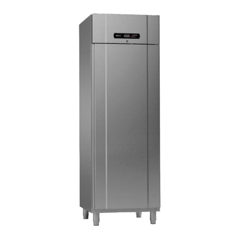
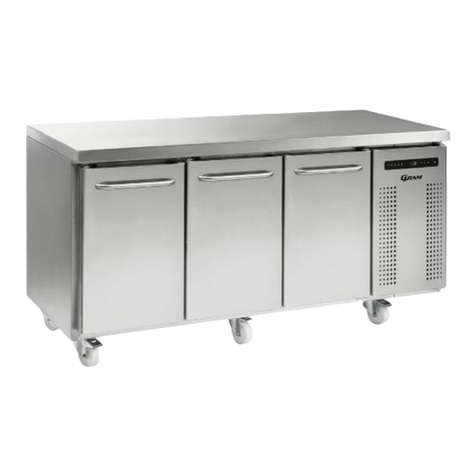
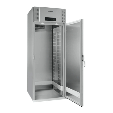
Gram Gastro 07/08 User manual

1
Service manual
GRAM GASTRO 07 / 08
Gram Commercial (CVR-nr. 41423986)
Aage Grams Vej 1
6500 Vojens, Denmark
Item number: 765042573
Release date: 06.12.21
Released by: JABP
Revision date:
Revision no.: 000
EN

2
Content
Scope of this service manual ............................................................................................................................................................... 4
Introduction to this manual .................................................................................................................................................................. 4
Intended use ........................................................................................................................................................................................ 5
Safety information ............................................................................................................................................................................... 5
Location ............................................................................................................................................................................................... 6
Optimizing the energy consumption .................................................................................................................................................... 7
General description ............................................................................................................................................................................. 8
Refrigerant / GWP value...................................................................................................................................................................... 9
Climate / temperature class ................................................................................................................................................................. 9
Electrical connection ......................................................................................................................................................................... 10
General use ....................................................................................................................................................................................... 11
Starting up ......................................................................................................................................................................................... 12
Temperature setting .......................................................................................................................................................................... 13
Error codes on the display ................................................................................................................................................................. 13
Troubleshooting ................................................................................................................................................................................. 14
User menu ......................................................................................................................................................................................... 15
Keylock .............................................................................................................................................................................................. 15
Defrosting .......................................................................................................................................................................................... 16
Defrost water ..................................................................................................................................................................................... 16
Power failure ..................................................................................................................................................................................... 17
Cleaning ............................................................................................................................................................................................ 17
Changing door hinge side.................................................................................................................................................................. 19
Door/drawer gaskets ......................................................................................................................................................................... 20
Long term storage ............................................................................................................................................................................. 20
Service .............................................................................................................................................................................................. 20
Disposal ............................................................................................................................................................................................. 21
EC-Declaration of conformity ............................................................................................................................................................. 22
UKCA-Declaration of conformity ........................................................................................................................................................ 23
The introduction. ................................................................................................................................................................................ 24
MPC 46 and the menus. .................................................................................................................................................................... 24
Software version and program variant in start-up sequence ............................................................................................................. 25
Defrosting .......................................................................................................................................................................................... 25
Temperature control and regulation: ................................................................................................................................................. 25
Temperature up: ................................................................................................................................................................................ 25
Temperature down: ........................................................................................................................................................................... 25
Key lock ............................................................................................................................................................................................. 26
Error codes in the display during normal operation ........................................................................................................................... 26
User menu ......................................................................................................................................................................................... 27
Visual and acoustic settings .............................................................................................................................................................. 28
Settings for running cycle .................................................................................................................................................................. 29
Test program for relays and electrical components ........................................................................................................................... 30
Display of current sensor inputs ........................................................................................................................................................ 31

3
Reset the controller to factory setting ................................................................................................................................................ 31
Parameter settings in commercial program variants ......................................................................................................................... 32
Plug connections onboard the controller ........................................................................................................................................... 33
Wiring diagram – K ............................................................................................................................................................................ 35
Wiring diagram – M ........................................................................................................................................................................... 36
Wiring diagram – F ............................................................................................................................................................................ 37
Piping diagram .................................................................................................................................................................................. 38

4
Scope of this service manual
This service manual is made in order to aid service technicians when servicing and troubleshooting on the
Gram Gastro 07/08 product range, and in particular related to the electrical controller.
The service manual is not intended to be handed over to end-users, since unintended changes of settings
potentially can cause situations where the temperature inside the cabinet cannot be kept as intended, (high
foodstuff temperatures can occur if wrong adjustments are made).
Another side effect of making unintended changes of the controller settings, is potentially causing damage to
the refrigeration system.
Changing service level parameter settings from the factory default, will void the warranty!
This service manual does explain how to access the different additional controller levels related to service.
These levels are:
Entering / adjusting factory default parameter settings (adjustable if necessary)
Entering and using the I/O test area
Furthermore, this manual does explain:
The layout of the controller and the different connections including the specifications of these.
EC declaration of conformity
Wiring diagrams for:
o K – Models (Refrigerator)
o M – Models (Extended refrigerator)
o F – Models (Freezer)
Piping diagram
Introduction to this manual
This manual will advise you how to service the product.
Changes in installation and other use of the product than described under intended use, might affect
the operation and durability of the product.
The manual is written according to our current technical knowledge. We constantly work on
updating this information, and we reserve the right to make technical changes.

5
User manual
Intended use
The product is intended for the storage of foodstuffs in non-household environments but not for the
display to or access by customers.
The product is designed for storage at a constant temperature and not be used for chilling down or
freezing hot/fresh foodstuff.
The product is only to be used for the purpose for which it has been expressly designed. Any other
use could cause that the foodstuff stored in the product is not kept at the correct temperature or
even damage the product.
The product is not suited for storing blood plasma, laboratory samples, pharmaceuticals or similar
substances.
The manufacturer will not be held liable or responsible for any damage caused by improper,
incorrect or unreasonable use of the product.
Safety information
Important
Description of symbols used in this manual.
Warning
Lacking observation to these instrucions might result in accidents with
personal in
j
ur
y
.
Important If these instructions are not observed, the product might be damaged or
destroyed.
Be aware that Gram Commercial has taken precautions to ensure that the safety of the product is
in order.
Please read carefully the following information regarding safety.
It is important, that everyone who are to use or install the product, to have access to
this manual.
This appliance is not intended for use by persons with reduced physical, sensory or
mental capabilities, or lack of experience and knowledge, unless they have been
given supervison or instruction concerning use of the appliance by a person
responsible for their safet
y
.
Children should be supervised to ensure that they do not play with the appliance.
The appliance might contain parts with sharp edges in the compressor compartment,
and in the inside compartment.
The appliance is not to be transported on a sack truck, there is a danger of loosing
the balance, causin
g
dan
g
er to persons.
Do not pull the power cord to dicconnect the appliance, or when moving the
appliance.

6
Location
When receiving the counter, check the packaging material for damage.
If any damage occurs at the packaging material, it should be considered if the cabinet might have
been damaged too. If the damage is substantial, please contact your dealer.
The transport pallet can be removed by loosening the screws that fasten the pallet to the counter.
This task requires at least 2 persons.
Fig. 1
If the counter has been transported in horizontal position it must stand upright at
least 2 hours before it is started to allow the oil from the compressor to run back.
Because of the heavy weight of the counter, the floor might be damaged or
scratched when moving the cabinet.
Correct set up gives the most effective operation.
The counter should be located in a dry and adequately ventilated room.
To ensure efficient operation, it may not be placed in direct sunlight or against heat-
emitting surfaces. The counter is designed to operate in an ambient temperature
between +16C and +40°C.
Avoid placement of the counter in a chlorine/acid-containing environment (swimming
bath etc.) due to risk of corrosion.
The counter and parts of the interior is equipped with a protecting film, which should
be removed before use.
Clean the counter with a mild soap solution before use.

7
The set up place must be level and horizontal.
For versions with legs, use the adjustable legs to make sure that the counter stands
level and upright.
Fig.2
For versions with castors, the locking devices of the two front castors must be activated, when the
cabinet is in place. The base must be level, and the counter may not be placed on frames or the
like.
Fig. 3
Optimizing the energy consumption
Correct set up gives the most effective operation.
The product should be located in a dry and adequately ventilated room.
To ensure efficient operation, it may not be placed in direct sunlight or against heat-emitting
surfaces. The product is designed to operate in an ambient temperature between +16C
and +40°C.
Do not keep the door open for too long.
Keep the condenser filter clean – to be cleaned at least every 2 weeks.
Do not set the temperature setpoint too low.

8
General description
Fig. 4
Front panel
Display
Worktop
Door
Drawer
Compressor
Condenser with air filter
Shelf for storage Gasket
Air inlet
Air filter

9
Refrigerant / GWP value
Refrigerator counter Refrigerant Charge kg GWP
CO2
equivalent t
K/M 1407 R290 0,097 3 0,00029
K/M 1807 R290 0,097 3 0,00029
K/M 2207 R290 0,097 3 0,00029
Freezer counter
F 1407 R290 0,050 3 0,000150
F 1807 R290 0,059 3 0,000177
F 2207 R290 0,060 3 0,000180
Climate / temperature class
Products are tested according to the following climate and temperature classes. Information about
the product’s climate and temperature class can be found at the name plate (see fig.9)
Climate class
3 25°C / 60 % RH
4 30°C / 55 % RH
5 40°C / 40 % RH
Temperature
class
L1 -18°C
M1 +5°C

10
Electrical connection
Read the text below thoroughly before electrical connection.
The cabinet is intended for connection to alternating current. The connection
voltage (V) and frequency (Hz) are shown on the name plate in the cabinet (see Fig.
9
)
. Onl
y
the supplied cord is to be used.
Never use an extension cord for this appliance!
If a wall socket is placed in a longer distance than the length of the supplied power
cord, contact an electrician to establish a wall socket within the range of the
supplied power cord.
If the product is defective, it must be examined by an authorized technician with
proper knowledge of the product during the guarantee period, if it is a product with
built-in compressor.
If it is a product connected to an external compressor unit, it must be examined by
the company who has connected the product to the unit.
Outside the guarantee period, it is advisable to use the service advised by your
dealer. If this is not the case, assistance is required from an authorized technician
with proper knowled
g
e of the product.
Always disconnect the power if interruptions in power supply occur, and when electrical parts are
removed/put on, and before cleaning and maintenance of the appliance.
Repairing of electrical/technical parts may only be performed by authorized technicians with
proper knowledge of the product.
Do not use the appliance before all coverings are installed, so that live or rotating machine parts
can not be touched.
The counter is not to be used outdoor.
All earthing requirements stipulated by the local electricity authorities must be observed. The
cabinet plug and wall socket should then give correct earthing. If necessary, contact an electrician.
Make sure the appliance is switched off at the socket before service is performed
on electrical parts. It is not sufficient to switch off the cabinet by the START/STOP
ke
y
as there will still be volta
g
e to some electrical parts of the counte
r
.

11
General use
Do not block vent holes in the front panel.
Do not damage the refrigeration system parts.
During normal operation, some parts of the refrigeration system in the
compressor compartment might reach high temperatures, and could therefore
cause burns if touchin
g
these components.
Do not use electrical devices inside the cabinet.
To ensure correct and efficient air flow in the cabinet, the shaded areas must be
kept free of products. (see Fig. 5)
All products to be stored, that are not wrapped or packed, must be covered in
order to avoid unnecessary corrosion of the inner parts of the cabinet.
If any controller parameters are changed from default, this could cause that the
appliance is not functioning normally, and harmful temperatures could damage
products that are kept inside the appliance.
If the appliance is turned off, wait minimum 3 minutes before turning the
appliance on again. This is to protect the compressor from damage
Maximum loading of wire shelf: 40 kg
Do not store explosive substances such as aerosol cans with flammable
propellant in this appliance.
Be aware, if bottles are stored near the air outlet, they may freeze up and break, causing a risk of
injury.
Do not pack the cabinet with foods. Allow some space between them to ensure a good airflow.
Moist or fresh foods and those with a strong smell should be wrapped up in a plastic film or
packed in a container. Otherwise the food may dry up or give their smell to other foods.
Foods containing acetic acid or yeast should be wrapped up in plastic film. Otherwise they may
accelerate corrosion of the evaporator and metal parts, resulting in failure.
Fig.5

12
Starting up
Display overview:
* = no function in this product.
Plug in the cabinet.
To start, press the START/STOP key.
During start up, the software version is displayed, followed by the software variant. The cabinet
temperature is displayed, when the cabinet starts normal operation.
The cabinet starts with a defrost, which is stopped shortly after, when the system has performed a
system check.
To cancel the defrost program, press keys and for more than 3 seconds. is turned off.
To turn off the cabinet, push for more than 3 seconds.
Shortcuts:
Key combination Time Function
> 3 seconds Start or stop manual defrosting
> 5 seconds Activation/deactivation of keylock
- Displays temperature setpoint
> 3 seconds Access to user menu and alarm settings
P
P+
+1
P
P+1
Code/parameter setting
Defrosting
Dry refrig.*
Rapid thaw* Temperature setting
Keylock
Start/stop

Temperature setting
Temperature control:
Press to see the cabinet temperature setting; the display will show the
set temperature.
Temperature regulation:
Keep pressed. At the same time, press or .
Each time or is pressed the temperature will change one degree.
When the display shows the desired temperature, let go of the two keys
and the setting has been made.
Error codes on the display
Displa
y
code Description
A
2 Local upper alarm LHL is or has been avtivated
A
4 External upper alarm EHL is or has been activated
F1 Room sensor error. In the meantime the counter itself will maintain the
set temperature by the memory of the controller. Temperature stability
will be affected.
Service assistance is required.
F2 Evaporator sensor error. Service assistance is required.
The counter will keep runnin
g
until the error has been mended.
F3* Condenser sensor error. The counter will keep running, until the error
has been mended. Service assistance is required.
F7* Indicates that the condenser temperature is too high. The cause might
be a clogged condenser, or too high ambient temperature.
If the condenser or air filter needs cleaning, the counter must be
disconnected at the mains power. Cleaning of the condenser is done
with a brush or a vacuum cleaner.
The air filter can be removed and cleaned in a dishwasher at max.
50C.
If the ambient temperature is too high, the placement of the counter
might be wrong, and an alternative place should be found. Ventilation
might help.
If this does not help, request service assistance.
* Applies only to counters with built-in compressor.
Acknowledgement of an alarm:
Acknowledge an alarm: push .
P
P+-
+-
P

14
Troubleshooting
Noise:
If abnormal noise occurs, request service assistance.
Operating sounds from compressor, condenser fan and interior fan are normal.
If sheet metal parts, front panels or panels in front of the compressor compartment are
making noise, these might be open. Close the panels.
Frosting inside compartment:
Ambient humidity too high.
The door is opened too often.
The door is left open for too long.
Damaged door gasket.
Poor cooling performance:
Ambient temperature too high.
The door is opened too often and/or open for too long.
The door is left open.
Damaged door gasket.
Room temperature setting too high.
Counter too packed with foods - air inlet/outlet blocked.
Condenser mesh filter is clogged.
Warm or hot foods inside.
Defrost in progress. The room temperature may rise temporarily during the defrost cycle,
but it will not affect the foods inside.
Some of the foods are frozen:
Counter too packed with foods - air inlet/outlet blocked.
Room temperature setting too low.
Condensation around the door:
Ambient humidity too high.
The door is not closed tightly.
Damaged door gasket.
Too high energy consumption:
Ambient temperature too high.
The door is opened too often and/or open for too long.
The door is left open.
Damaged door gasket.
Room temperature setting too low.
Counter too packed with foods - air inlet/outlet blocked.
Condenser mesh filter is clogged.
Warm or hot foods are brought into the cabinet too often.
Counter placed in direct sunlight or close to heat-emitting surfaces.
The default settings have been changed.

15
User menu
This chapter includes setting of alarm values.
The alarm system is divided into 2 systems. The one system only triggers local alarms, which
means that the error codes are only shown at the display.
The other alarm system triggers both alarms at the display, but it also activates the remote alarm
outlet. Each alarm system operates independently of each other.
If a change of the setting is required, get access to the menu by pushing for more than 3
seconds. The values are changed by pushing the or keys. The new setting is saved by
pushing . To exit the menu, push .
Menu access P + 1
Local alarm setting LAL LhL °C Setting the upper alarm limit. At alarm,
the displa
y
shows: A2
Lhd min. Time dela
y
for the upper alarm limit.
BU On/off Activation of buzzer. The buzzer
sounds at alarms A1, A2.
(
1=on / 0=off
)
External alarm setting EAL EHL °C Setting the upper alarm limit. At alarm,
the displa
y
shows: A3
ELL °C Setting the lower alarm limit. At alarm,
the displa
y
shows: A4
EHd min. Time dela
y
for the upper alarm limit.
ELd min. Time dela
y
for lower alarm.
Temperature offset
(
sensor calibration
)
CAL CA K -5…+5 K
Escorting alarm limits ALL FAS/ESC Activation of escorting alarm limits.
FAS= fixed limits / ESC = limits
followin
g
the setpoint
No. of defrosts dEF 4 Number of defrosts in 24 hours.
Keylock
The keypad can be locked by simultaneously pushing for more than 5 seconds.
lights to indicate that the keys are locked, and a short beep sounds. Now it is not possible to
use the keys for temperature setting etc.
The same code is to be used for unlocking the keypad again.
P+1
+-
P
+1

16
Defrosting
Defrosting is automatically performed 4 times every 24 hours. If the counter is operating under
severe load (frequent door opening and frequent replenishment), manual defrosting can become
necessary.
Starting manual defrosting: push simultaneously for more than 3 seconds.
The next defrost will occur 6 hours later. lights up to indicate a defrosting cycle.
It is possible to change the number of defrosts. See the chapter “User menu” for setting.
Do not use sharp or pointed objects to accelerate the defrosting
process.
Defrost water
Counters with compressor
Defrost water is led through a pipe, from the evaporator and into a tray behind the condenser.
Here, the water is evaporated by heat from the condenser.
Counters connected to a common compressor
The defrost water is led through a pipe to a tray behind the front panel, from where it is evaporated
by a heating element.
It is recommended to clean the tray at least once a year. Remember to disconnect
the counter before cleaning.
Fig. 6
P +

17
Power failure
In the event of a power failure, the control remembers the temperature setting and restarts the
counter when power is restored. If the power failure persists for some time, the control might revert
to the factory setting.
Cleaning
Insufficient cleaning will cause that the counter will not work at optimum perfomance, or eventually
it will be defective.
Before cleaning, the counter should always be disconnected.
Do not flush the counter with water, do not use water jet or steam hose
as this ma
y
cause short-circuits in the electrical s
y
stem.
Cleansing agents containing chlorine or compounds of chlorine as well
as other corrosive means, are not to be used, as they might cause
corrosion to the stainless panels of the cabinet and the evaporator.
The compressor compartment and in particular the condenser must be kept free
from dust and dirt. This is best done with a vacuum cleaner and a brush.
The air filters on the condenser and the front panel can be removed and cleaned in
a dishwasher at max. 50°C.
For the external maintenance – use stainless steel polish.
The counter should be cleaned internally with a mild soap solution at suitable
intervals and checked thoroughly before it is put into operation again.
Cleaning of counters with drawers:
If the counter is equipped with drawers and the bottom, sides or back wall require cleaning, the
drawers can be removed as follows (see Fig. 7a,7b,7c):
Pull out the drawer. Lift it up, after which the drawer can be pulled of the extension rails.
After cleaning, the drawer can be replaced. Place the drawer on the outer wheels on the telescopic
rails. Lower the drawer into a horizontal position after which it can be pushed into a closed
position. The drawer is now securely positioned.

18
Fig.7a
Fig.7b
Fig.7c

19
Changing door hinge side
The door can be changed from righthand-hinged to lefthand-hinged or vice-versa.
To do so, proceed as follows:
Fig. 8
1. Remove the hinge at pos. A.
2. Lift off the door.
3. Remove the hinge at pos. B.
4. Move cover plugs in the cabinet from pos. D to pos. A and from pos. C to pos. B.
5. Move the cover plug in the door from pos. D to pos. A, too.
6. The hinge previously mounted at pos. A is now mounted at pos. C.
7. The door is now placed at the hinge at pos. C.
8. The hinge previously mounted at pos. B is now mounted at pos. D and adjusted, so that the
door is closing properly. Then tighten the screws.

20
Door/drawer gaskets
This chapter deals with the importance of a well-functioning gasket.
Gaskets are an important part of a refrigerator/freezer. Gaskets with reduced functionality, reduces
the tightness of the counter. Reduced tightness might cause increased humidity, internal icing, an
iced up evaporator (leading to reduced refrigeration capacity), and in worst case reduced lifecycle
of the counter.
Therefore it is important to be aware of the condition of the gasket. Regular
inspection is recommended.
The gasket should be cleaned regularly with a mild soap solution.
If a gasket needs replacement, contact your supplier.
Long term storage
If the counter is taken out of operation, and need to be prepared for long-term storage,
clean the inside compartment, the door and door gasket thorougly with a hot soapy damp cloth.
Eventual remnants of food could create mould.
Service
The refrigerating system and the hermetically sealed compressor require no
maintenance - they merely must be kept clean.
If refrigeration fails, first investigate whether the unit has been unintentionally disconnected or
switched off at the socket, or whether a fuse has blown.
If it is not possible to find the cause of the refrigeration failure, please contact your dealer.
When reporting a malfunction please state the type and serial number (S/N) of the cabinet. This
information is found on the name plate, see Fig. 9.
Fig.9
Aage Grams Vej 1, 6500 Vojens
Type K 1407 CSG A DL DR L2 E
Part No 951400021
PO No 1032171 YYYY-WW2021-49
S/N 10285490
Foam Propellant Cyclopentane
Permissible operation over-pressure: Suction side:
Discharge side:
Gram Commercial, Denmark
10109429
10285490
Input: 230 V50 Hz 231 W1,29 A
Defrost 360 w
Refrigerant R290
CO2e 1
Climate class 5 (M1)
Isolation class IP21
10,0 bar
25,0 bar
97g
Made in DK. CVR nr. 41 42 39 86
Other manuals for Gastro 07/08
1
Table of contents
Other Gram Commercial Food Equipment manuals
Popular Commercial Food Equipment manuals by other brands

Lincoln
Lincoln Impinger X2 Ovens with Push Button Controls... Service manual

Iarp
Iarp EIS.3 Use and maintenance

CombiSteel
CombiSteel 7178.1105 Instruction and maintenance manual

Bonnet Neve
Bonnet Neve CURL HOT User instructions

GGM gastro
GGM gastro TWK1756 instruction manual

Goldmedal
Goldmedal Unifloss Top 3034 instruction manual

Alico
Alico Metro WavDri Instructions for use

Alto-Shaam
Alto-Shaam 500-1D Operation and care manual

Southbend
Southbend DMT-30 owner's manual

GGM gastro
GGM gastro BWIN621 instruction manual

Alto-Shaam
Alto-Shaam 300-s Installation, operation and maintanance manual

Goldmedal
Goldmedal ReadyPop Jr 2783-00-000 instruction manual