Zero Zone HYBRID RHLC30 User manual

ZERO ZONE
HYBRID™DISPLAY CASES
Reach-In Coolers & Freezers and Open Multi-Decks
INSTALLATION, OPERATION, & MAINTENANCE MANUAL
COMPLIANT
66-0034 REV H • JAN 2022

II
Table of Contents
INTRODUCTION.....................................................................................................1
PLANNING..............................................................................................................3
DELIVERY...............................................................................................................4
Moving Display Case........................................................................................4
SETTING THE CASE..............................................................................................5
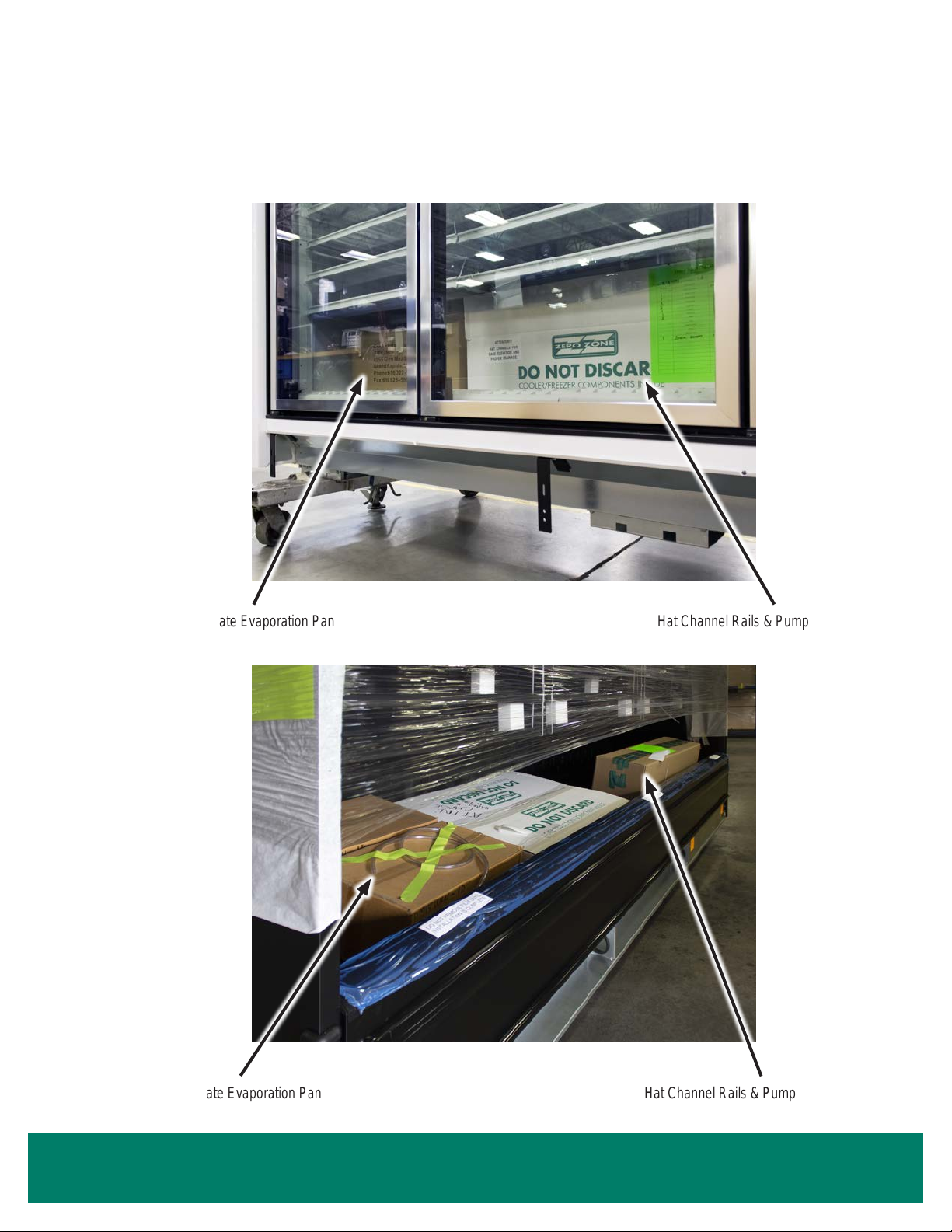
Contents Shipped Inside of Case.....................................................................5
Positioning Hat Channel Rails..........................................................................6
Dividers Between Cases...................................................................................7
Reveal Merchandiser® Support Brace - Removal & Installation......................8
Reveal Merchandiser® Support Brace - Position Components......................11
CONDENSING UNIT CONNECTION....................................................................12
Setting the Condensing Unit...........................................................................12
Quick-Connect Couplings...............................................................................13
Insulation on Suction Line Quick-Connect......................................................14
ELECTRICAL/CONTROL.....................................................................................15
Case Electrical Connections - Highlight Merchandiser®................................15
Case Electrical Connections - Crystal Merchandiser®...................................16
Case Electrical Connections - Reveal Merchandiser®...................................17
Case Electrical Connections - Pinout Locations.............................................18
Condensing Unit Electrical Connections.........................................................19
PLUMBING...........................................................................................................20
Pump with Bracket Installation Instructions....................................................20
Dual Evaporation Pan Set Up.........................................................................24
Power the Condensate Evaporation Pan........................................................25
Case Drain Line to Floor Drain ......................................................................26
Booster Pump Installation...............................................................................27
CASE TRIM...........................................................................................................28
Bumper & Kickplate........................................................................................28
OPERATION .........................................................................................................29
Controller Sensor Wires..................................................................................29
Start-Up...........................................................................................................30
Carel IR33+ Controller Standard Features.....................................................30
Instructions for Setting the Time - Carel IR33+ Controller..............................30
Turning the Lights On & Off............................................................................31
Solid Shelf Installation & Removal..................................................................32
Wire Shelf Installation & Removal...................................................................33
Door Hold-Open Bracket.................................................................................34
Electrical Enclosure Wire Colors.....................................................................35
When installing a Hybrid Merchandiser™, refer to both this manual and the associated
remote installation & operation manual.

III
MAINTENANCE....................................................................................................36
Cleaning..........................................................................................................36
Under Case Floor Cleaning (NSF)..................................................................36
Using the Condensate Removal System........................................................37
Cleaning the Condensate Removal System...................................................37
Preventative Maintenance for Condensing Units & Evaporator Coils.............37
CONTROLLER OPERATION ...............................................................................38
Carel IR33+ Programming Instructions...........................................................38
Carel IR33+ Low Temp Reach-In Codes........................................................39
Carel IR33+ Medium Temp Reach-In Codes..................................................41
Carel IR33+ Medium Temp Open Multi-Deck Codes......................................42
Basic Carel IR33+ Operations........................................................................43
Carel IR33+ Display Legend...........................................................................43
Basic Case Operations...................................................................................44
Defrost Schedule............................................................................................44
Silencing the Carel IR33+ TemperatureAlarm................................................44
Conditions that Trigger the TemperatureAlarm ..............................................45
Carel IR33+ Verify and/or Change Parameters..............................................46
Dixell XR75CX Front Panel Commands.........................................................49
Dixell XR75CXAlarm Signals.........................................................................50
Dixell XR75CX Connections...........................................................................51
Condensing Unit Pressure Switch Settings....................................................52
SHROUD INSTALLATION INSTRUCTIONS........................................................53
Standard ShroudAssembly............................................................................53
Signage ShroudAssembly..............................................................................57
ShroudAssembly for Case Lineup..................................................................58
OPTIONS..............................................................................................................59
Noise Reduction Kit........................................................................................59
Balloon Guard Kit............................................................................................61
Optional Disconnect Installation......................................................................63
CAREL IR33+ EMERGENCY GUIDE...................................................................64

ZERO ZONE WARRANTY
SYSTEMS DIVISION
6151 140thAve NW
Ramsey, MN 55303
Phone: 763-398-1996
Toll Free: 800-708-3735
CASE DIVISION
110 N Oakridge Drive
North Prairie, WI 53153
Phone: 262-392-6400
Toll Free: 800-247-4496
the responsive company™
DC-01-F • SEP 2019
Limited Warranty
Zero Zone, Inc. (Seller) hereby warrants that any products manufactured by it and sold are warranted to be free from defects in material and
workmanship, under normal use and service for its intended purpose, for a period of one (1) year from the date of original installation (not to
exceed 15 months from the date of factory shipment). Zero Zone ChillBrite®LED Lighting carries a 5-year parts warranty. Zero Zone CoolView®
Doors carry a 10-year glass pack parts warranty. The obligation under this warranty shall be limited to repairing or exchanging any part, or parts,
FOB Factory, which is proven to the satisfaction of the Zero Zone Service Department to be defective. Zero Zone reserves the right to inspect
the job site, installation, and reason for failure. This limited warranty does not cover labor, freight, or loss of food or product, including refrigerant
loss. This warranty does not apply to motors, switches, controls, lamps, driers, fuses, or other parts manufactured by others and purchased by
the Seller unless the manufacturer of these items warrants the same to the Seller, and then only to the extent of those manufacturer’s warranty
to the Seller.Any products sold on an “AS IS” basis shall not be covered by this warranty.
Extended Warranties
In addition to the standard limited warranty, for further consideration, the Seller will extend to the original purchaser prior to shipment, a limited
extended warranty on the compressor only, following expiration of the standard warranty. The Seller agrees to repair or exchange, at its option,
or provide reimbursement for such exchange as directed, less any credit allowed for return of the original compressor, of a compressor of
like or similar design and capacity, if it is shown to the satisfaction of Zero Zone that the compressor is inoperative due to defects in factory
workmanship or material under normal use and services as outlined by Zero Zone in its Installation & Operation Manuals and other instructions.
Length of Extended Warranty
Any compressor warranty may be extended for an additional four (4) years, but such extension must be purchased prior to shipment to be
effective.This warranty is only for the compressor and not for any other associated parts of the refrigeration system.
Product Not Manufactured by the Seller
The written warranty, if any, provided by the manufacturer of any part of the refrigeration unit sold by Seller to Buyer, but not manufactured by
Seller, is hereby assigned to the Buyer. However, Seller makes no representation or warranty regarding the existence, validity, or enforceability
of any such written warranty.
Limitation and Exclusion of Warranties
THE WARRANTIES SET FORTH HEREINARE EXCLUSIVEAND IN LIEU OFALL OTHER WARRANTIESAND REMEDIES WHATSOEVER,
INCLUDING, BUT NOTLIMITED TO, IMPLIED WARRANTIES OF MERCHANTABILITYAND/OR FITNESS FORAPARTICULAR PURPOSE.
ZERO ZONE WARRANTY

Introduction • 1
INTRODUCTION
Important User Information
Copyright © 2022 Zero Zone, Inc.
All rights reserved. No part of the contents of this manual may be reproduced, copied, or transmitted in any form or by any means including
graphic, electronic, or mechanical methods or photocopying, recording, or information storage and retrieval systems without the written
permission of the publisher, Zero Zone, unless it is for the purchaser’s personal use.
The information in this manual is subject to change without notice and does not represent a commitment on the part of Zero Zone. Zero Zone
does not assume any responsibility for any errors that may appear in this manual. In no event will Zero Zone be liable for technical or editorial
omissions made herein, nor for direct, indirect, special, incidental, or consequential damages resulting from the use or defect of this manual.
The information in this document is not intended to cover all possible conditions and situations that might occur. The end user must exercise
caution and common sense when installing, using, or maintaining Zero Zone products. Zero Zone products should only be installed by qualied,
professional refrigeration technicians. If any questions or problems arise, call Zero Zone at 800-247-4496.
Any change to a Zero Zone product made during the installation, start-up, or at any other time must be submitted in writing to Zero Zone for
approval and be approved by Zero Zone in writing prior to commission. The product warranty is voided when any unapproved change is made
to a Zero Zone product.
Manufacturer
Zero Zone, Inc.
Display Case Division
110 N Oakridge Dr • North Prairie, WI 53153 • 800-247-4496 • www.zero-zone.com
Intended Use
Zero Zone products are intended to be installed and used as described in this manual and other related Zero Zone literature, specications,
drawings, and data.All Zero Zone products must be leveled after being installed.
Display Case Models
The information contained in this manual pertains to the following Zero Zone display cases:
CASE MODEL DESCRIPTION DOOR SIZE & TYPE
RHLC30 Low Temp Highlight Merchandiser®30" x 68" CoolView®Envision®Doors
RHLC30T Low Temp Tall Highlight Merchandiser®30" x 73" CoolView®Envision®Doors
RVLC30 Low Temp Crystal Merchandiser®30" x 74" CoolView®Ultra™Doors
RHCC24 Medium Temp Highlight Merchandiser®24" x 68" CoolView®Ultra™French Doors
RHMC30 Medium Temp Highlight Merchandiser®30" x 68" CoolView®Envision®Doors
RHMC30T Medium Temp Tall Highlight Merchandiser®30" x 73" CoolView®Envision®Doors
RVMC24 Medium Temp Crystal Merchandiser®24" x 74" CoolView®Ultra™French Doors
RVMC30 Medium Temp Crystal Merchandiser®30" x 74" CoolView®Ultra™Doors
ORMC82 Medium Temp Reveal Merchandiser®N/A
Reveal Merchandiser®is a registered trademark of Zero Zone, Inc. in the United States.

2 • Introduction
INTRODUCTION
Case Features
Zero Zone produces high quality refrigerated display cases using state-of-the-art components. The cases are built with the thickest insulation in
the industry and a high efciency evaporator coil. Case features include:
Brushless DC electronic motors
Zero Zone ChillBrite®LED Lighting
Zero Zone CoolView®standard-energy or no-energy doors (Crystal Merchandiser®and Highlight Merchandiser®only)
Testing Standards
These display cases were designed and tested using the following industry standards:
NSF 7 – Commercial Refrigerators and Freezers (ANSI Approved) (equipment certied by NSF)
NSF 51 – Food Equipment Materials (ANSI Approved) (equipment certied by NSF)
UL 471 – Commercial Refrigerators and Freezers (ANSI Approved) (equipment certied by ETL)
ASHRAE Standard 72 – Method of Testing Commercial Refrigerators and Freezers (ANSIApproved)
AHRI 1200 – Performance Rating of Commercial Refrigerated Display Merchandisers and Storage Cabinets (ANSIApproved)
DOE Compliant (All U.S. Sales and U.S. Territories)
ASHRAE Standard 72 species the test conditions for the equipment. It includes the ambient conditions of 75°F dry bulb and 55% RH. It also
species the door opening requirements for the performance test. Doors are opened six times in one hour for six seconds. The door opening
test period is for eight hours during one 24-hour performance test.As an example, a 5-door case will have 240 door openings during one 24-
hour test. Consult the factory if your store exceeds these test conditions.
Hybrid™cases are tested and listed as remote commercial refrigerators. The scope of this manual covers Hybrid™ congurations of the Zero
Zone cases for Crystal Merchandiser®, Highlight Merchandiser®, and Reveal Merchandiser®.

Planning • 3
PLANNING
PERMITTING
Required case permits for Hybrid™ installation should be classied as “remote equipment.”
Always check with the local inspector to make sure your installation complies with local code requirements.
Does your permitting require there to be seismic restraints?
REMOTE MONITORING
Remote monitoring is an option that is available for the case(s).
ENTRANCE & UNLOADING
What is the height of the entryway that the case(s) will need to go through? This should be addressed in the order stage.
Where will the case(s) be unloaded from the truck? Is there room for the case(s) to be unloaded from the truck?
CASE INSTALLATION & MOBILIZATION
Are you able to maneuver the case(s) throughout the store to nal location?
The condensing unit will produce some noise. Has this been taken into account when identifying the nal location for these case(s)?
Have you considered the door opening/swing and aisle width (for Crystal Merchandiser®or Highlight Merchandiser®)?
HEAT REJECTION
Has the rejected heat from condensing unit(s) into store been considered?
Do you have adequate room around the case(s) for the condensing unit to be able to reject heat? There should be a 30" minimum
clearance between the top of shroud and the store ceiling.
Options/considerations if the clearance is less than the 30" minimum:
Add “egg crate” ceiling panels to the store ceiling.
Add auxiliary fans to dissipate heat.
Use louvered case shrouds.
Use an alternate shroud height (contact your Zero Zone Sales Representative).
ELECTRICAL
Is there suitable power supply for necessary voltage and amperage?
Is the appropriate circuit breaker installed and available in the store power panel?
Do you want/need an electrical disconnect at the case(s)?
Is there a separate electrical connection available for condensate evaporation pans (for Reveal Merchandiser®)?
PLUMBING
Will you be using a oor drain? Can the proper slope to the drain be provided?
Will you be using a pump with the condensate evaporation pan system? This setup will add humidity to the store.
HIGH HUMIDITY
Do you need an auxiliary fan system to provide air movement along the back and underneath the case(s)?
Do you need louvered kickplates for air to be able to move underneath the case(s)?
Review everything on this page before placing an order

4 • Delivery
DELIVERY
ATTENTION FORKLIFT OPERATOR!
Forks must be 48" long, 1 1/2" to 1 3/4" thick, and no more than
4" wide to t the bases. 2 to 5-door cases and 4' to 12' open multi-
decks are fork-liftable from either end of the case. 1-door cases are
not fork-liftable through a standard doorway.
24" 2-Door Cases or 4' Open Multi-Decks:
Forks must extend 20" to 24" under the case.
30" 2-Door or 24" 3-Door Cases or 6' Open Multi-Decks:
Forks must extend 26" to 30" under the case.
30" 3-Door or 24" 4-Door Cases or 8' Open Multi-Decks:
Forks must extend 39" to 43" under the case.
30" 4- & 5-Door or 24" 6-Door Cases or 12' Open Multi-Decks:
Forks must extend 44" to 47" under the case.
1. Remove the upper electrical box by disconnecting
the 3 wiring connectors, then remove the 4 screws
that attach the electrical box to the top of the case.
2. Remove the piping bracket from the back of the
case.
3. Pull quick-connect lines away and down from the
case.
4. Once inside, reposition quick-connect lines,
reinstall bracket, and set electrical box on top.
Do not leave, store, or hold case outdoors in direct sunlight or high ambient temperature. With the end panels on, a display case
with doors will be airtight; the inside temperature of the case will increase, and the heat will be unable to escape. This could
potentially cause any plastic (such as PTM) inside the case to melt.
TO GET THROUGHA DOORWAY, IT MAY BE NECESSARY TO TEMPORARILY DISMOUNT THE REFRIGERATION
LINESAND THE TOP ELECTRICALBOX.
Temperature
Probe Wires
Note: Set the case at least 3" away from the wall to allow for air circulation and piping.A 3" standard (or 6" optional) standoff spacer
is required between the rear wall and the case.
Moving Display Case
Piping Bracket

Setting the Case • 5
SETTING THE CASE
Hat Channel Rails & PumpAssemblyCondensate Evaporation Pan
Contents Shipped Inside of Case
Highlight Merchandiser®Shown
Reveal Merchandiser®Shown
Hat Channel Rails & PumpAssemblyCondensate Evaporation Pan

6 • Setting the Case
SETTING THE CASE
Position hat channel rails with tape up.
1-door cases do not need hat channel rails.
2-door cases and 4' open multi-decks get 2 hat channel rails.
3 and 4-door cases and 6' and 8' open multi-decks get 3 hat channel rails. The center rail must be
angled to rest on the front and back bases. Do not position under drain hub!
5 and 6-door cases and 12' open multi-decks get 4 hat channel rails. Position as shown.
In most instances, shims must be added to make cases level. The shims are placed perpendicularly
under the hat channel rails (as illustrated bottom right). Refer to the appropriate remote display case
installation and operation manual (leveling section) for details.
Positioning Hat Channel Rails
Refer to the associated remote installation & operation manual for more information about setting and leveling a display case,
including base locations, optional bases, proper shimming, case squareness, case joining, and lineup assembly.
Hat Channel
Raill
Hat Channel
Raill
Highlight Merchandiser®Shown

Setting the Case • 7
SETTING THE CASE
Dividers Between Cases
Clear plexi dividers separate refrigeration circuits
between same temperature cases.
Insulated dividers separate different temperature
cases in lineups.
Both types of dividers are factory-installed prior to shipping.

8 • Setting the Case
SETTING THE CASE
Reveal Merchandiser®Support Brace - Removal & Installation
An 8' or 12' Reveal Merchandiser®in a Hybrid™ conguration will be shipped with a support brace that strengthens its canopy. This
support brace can be removed in order to move the case through a low doorway; this reduces the height by ~3". The support brace
must be reinstalled before the condensing unit is placed on top of the display case and before the display case is set against a wall.
DESCRIPTION 8' CASE QUANTITY 12' CASE QUANTITY
Ceiling Support Braces 2 3
Rear Wall Support Braces 2 3
Piping Cutout Support Brackets 4 6
1" Hex Screws 32 48
5" Hex Bolts 8 12
Washers 16 24
1/2" Round Spacers 8 12
Lock Nuts 8 12
An 8' Reveal Merchandiser®(8ORMC) uses 2 support braces.A12' Reveal Merchandiser®(12ORMC) uses 3 support braces.
Support BraceAssembled & Shipped. 8' Reveal Merchandiser®Shown.

Setting the Case • 9
SETTING THE CASE
Reveal Merchandiser®Support Brace - Removal & Installation
REMOVING THE SUPPORT BRACE
Save all bolts and fasteners for reassembling the support brace after moving the display case through the doorway.
1. Detach the rear wall support brace from
the back of the case, starting from the
bottom and working up to the top.
2. Unbolt the piping cutout brackets from
the rear wall support brace and the
case.
3. While supporting the rear wall support
brace, remove the joint through-bolts
that connect the ceiling support brace
to the rear wall support brace. This
consists of 5" bolts, washers, 1/2"
spacers, and lock nuts.
4. Remove the rear wall support brace.
5. Detach and remove the ceiling support
brace from the top of the case.
Hex Screws
Piping Cutout
Support Bracket
Rear Wall
Support Brace
Piping
Cutout
Hex Screws
1/2" Spacer
Washers
Lock Nut
Ceiling
Support
Brace
5" Bolts
Washers
Support Brace Components
Detach/Reattach Rear Wall Brace
Rear Wall
Support Brace
Unbolt/Bolt Piping Cutout Brackets
Piping Cutout
Support Bracket

10 • Setting the Case
SETTING THE CASE
Reveal Merchandiser®Support Brace - Removal & Installation
REINSTALLING THE SUPPORT BRACE
Reassemble the support brace after moving the display case through the doorway. Reuse the bolts and fasteners that were removed.
The support brace must be installed before the condensing unit is placed on top of the display case and before the display case is set
against a wall.
Separate/Join Ceiling & Rear Support Braces
Remove/Reinstall Ceiling Support Brace
1. Install the ceiling support brace on top of the case.Align the ceiling support brace with the holes in the backer plates and use the hex
screws to fasten it.
2. Join the ceiling support brace to the rear wall support brace using through-bolts.Add the 5" bolt and a washer on one side through the
support braces, and add a 1/2" spacer, washer, and lock nut on the other side. Note: Position the case piping to pass through the
piping cutout in the rear wall support brace.
3. Align the rear wall support brace with the holes in the backer plates.
4. Install the piping cutout support brackets to each mounting ange of the rear wall support brace, spanning the piping cutout. The provided
screws will bite into the rear wall of the display case.
5. Install the rear wall support brace to the back of the case. Push it ush against the back of the case and then use the hex screws to fasten it
the display case, starting from the bottom.

Setting the Case • 11
SETTING THE CASE
Reveal Merchandiser®Support Brace - Position Components
An 8' or 12' Reveal Merchandiser®in a Hybrid™ conguration will be shipped with a support brace that strengthens its canopy.
Position the condensing unit, electrical box, evaporation pans, and other features around the support braces.
An 8' Reveal Merchandiser®uses 2 support braces.
A12' Reveal Merchandiser®uses 3 support braces.
8' Reveal Merchandiser®Shown
Support
Braces
Condensing
Unit
Condensate
Evaporation
Pans
Electrical
Box
8' Reveal Merchandiser®Shown
DR-821-F
1 1/2"
End Panel Condensate
Evaporation
Pans
Tubing
Ports
Electrical
Box
Support Braces
Condensing
Unit
Air Flow
Condensate Pump

12 • Condensing Unit Connection
CONDENSING UNIT CONNECTION
2. Place condensing unit with quick-connect couplings facing the back of the case.
3. Avoid scratching the front of the case.
1. Locate quick-connect couplings on the back of the case.
Setting the Condensing Unit
CONDENSING UNIT CONNECTION

Condensing Unit Connection • 13
CONDENSING UNIT CONNECTION
THIS ISTHE MOSTIMPORTANT PARTOFAHYBRID™CASE INSTALLATION
1. Align the couplings and pre-lubricate the mating surfaces (threads and o-rings) with POE oil (supplied) before connecting them. Not
lubricating the mating surfaces may increase the potential for leaks.
2. Start with hand tightening to ensure a good seal.
3. Tighten couplings with a wrench until couplings are fully threaded. Use the wrench size and torque values provided in the table below.
4. After all connections are made, check the couplings for leaks.
WRENCH SIZE QUICK-CONNECT SIZE TORQUE VALUES
13/16" 3/8" 10-12 ft./lbs.
1 5/16" 1/2" 35-45 ft./lbs.
1 5/16" 5/8" 35-45 ft./lbs.
1 5/16" 7/8" 35-45 ft./lbs.
Quick-Connect Couplings
We recommend using a torque wrench and crowsfoot wrench.

14 • Condensing Unit Connection
CONDENSING UNIT CONNECTION
Insulation on Suction Line Quick-Connect
Apre-cut piece of split piping insulation (supplied) will be required on each freezer suction line quick-connect
coupling. Cable ties will also be provided.
1. Wrap piping insulation around the suction line quick-connect coupling. Position the insulation so that it
completely covers the quick-connect. (Insulation should not be added to the liquid line.)
2. Remove lm from adhesive strip on the insulation and adhere to other end.
3. Use cable ties to secure the insulation in place.

Electrical/Control • 15
ELECTRICAL/CONTROL
Case Electrical Connections - Highlight Merchandiser®
Connecting power to a Highlight™Hybrid™does not require opening the electrical box at any time.
Always refer to the wiring diagrams shipped with your case.
CONN-1
Wiring to
Case
CONN-2
Wiring to
Condensing Unit
CONN-3
Temperature Sensors
to Controller
Connects to
CONN-1 on
Electrical Box
Connects to
CONN-2 on
Electrical Box
"CONN-1" carries power from the case electrical box to the case.
"CONN-2" carries power from the case electrical box to the condensing unit electrical box.
"CONN-3" connects to the temperature sensors. (See "Controller Sensor Wires" on page 29
for more information.)
Each connector is keyed for the correct attachment. Orient the "CONN-X" label on the plug at the
12 o'clock position to align the connector keying. Push the wire harness plug into the bulkhead,
then turn the threaded nut clockwise. The parts will lock together when a detent is felt.
See "Case Electrical Connections - Pinout Locations" on page 18 for information about the
connectors.
HIGHLIGHT™COOLER
CONN-1
Wiring to
Case
CONN-2
Wiring to
Condensing Unit
CONN-3
Temperature Sensors
to Controller
Connects to
CONN-1 on
Electrical Box
Connects to
CONN-2 on
Electrical Box
HIGHLIGHT™FREEZER
ELECTRICAL/CONTROL
Align labels, push together,
and turn clockwise.

16 • Electrical/Control
ELECTRICAL/CONTROL
Power runs from the store panel disconnect switch to the condensing unit electrical box and then to the case electrical box.
Cases receive 208V 4-wire service; 115/208V/1/60Hz; red and black power, white neutral, green ground (eld connection).
DO NOT ENERGIZE POWER UNTILALL COVERSARE ON ALLELECTRICALBOXES.
Case Electrical Connections - Crystal Merchandiser®
Always refer to the wiring diagrams shipped with your case.
CRYSTAL™COOLER CRYSTAL™FREEZER
Wiring to
Condensing
Unit
Wiring to
Case
This manual suits for next models
8
Table of contents
Other Zero Zone Commercial Food Equipment manuals
Popular Commercial Food Equipment manuals by other brands

KegLand
KegLand KL38126 instructions

Redfox
Redfox BMPK 2120 ECO Instructions for installation and use

Hatco
Hatco HEATMAX HWBC Series Installation and operating manual

LINKRICH
LINKRICH LR-13A user manual

UNIS
UNIS BIG HORN operating manual

KBS
KBS NGWT 3-55/SN Installation, operation and maintenance instructions

Cres Cor
Cres Cor H137WSUA12 Operating and maintenance instructions

Silver King
Silver King SKMB Technical manual and replacement parts list

Schaerer
Schaerer Siena-2 user manual

saro
saro ES 903 PZ 1/4 operating instructions

BIMG
BIMG Metvisa DG.10 instruction manual

Flavor Burst
Flavor Burst CTP 44SS-DLX instruction manual