5
b i o l ine
4
Manufactured by
Gram Scientic ApS
Aage Grams Vej 1 · 6500 Vojens · Denmark
Tel: +45 73 20 13 00
Table of Content
Copyright © 2006- Gram BioLine, a division of Gram Scientic ApS,
Denmark. All rights reserved.
The content of this publication is owned by Gram BioLine, unless
otherwise noted, and is protected by Danish and international copyright
laws and provisions. Information and images may not be used, copied or
transferred without the express written permission of Gram BioLine.
This instructions for use is intended for the following product series:
BioCompact II
We recommend that you read this instructions for use through thoroughly before using the cabinet for the rst time.
Gram Scientic does not guarantee safe operation if the cabinet is used for anything other than its intended use.
Contents of the instructions for use can be subject to change without notice. No part of this instructions for use may be
reproduced in any form without expressed written consent of Gram Scientic. Gram Scientic guarantees the cabinet
under certain warranty conditions. Gram Scientic is in no way responsible for any loss or damage of content. This
instructions for use should be considered an integral part of the cabinet, and should be stored close to the cabinet and be
easy to access. If the instructions for use is lost, please refer to your local distributor or Gram Scientic for a replacement.
For current versions of the manual, please go to www.gram-bioline.com.
Make sure to read the instructions for use through thoroughly before using the cabinet for the rst time.
In
the
event
of
need
for
product
support,
do
not
hesitate
to
contact
us
at:
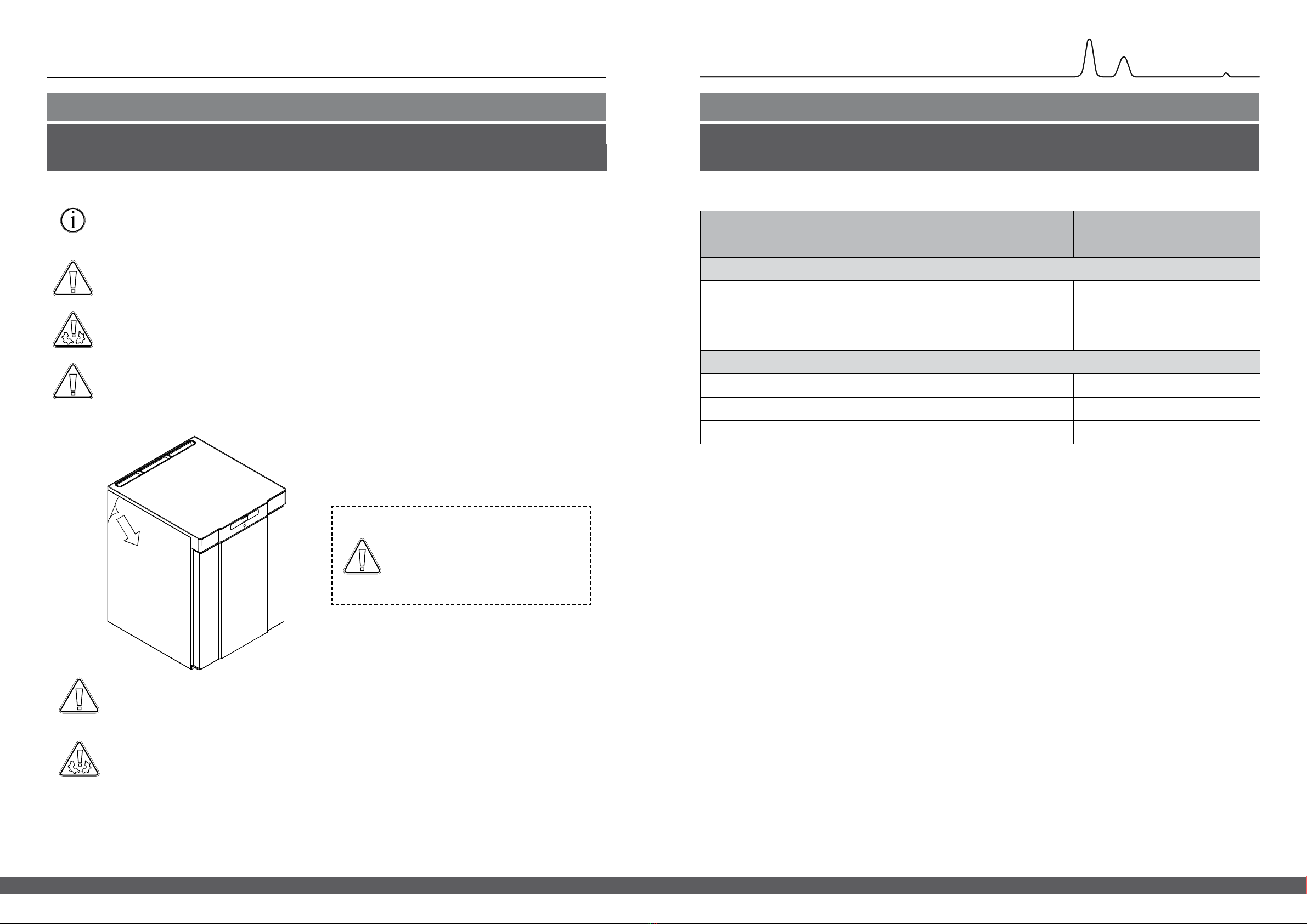
[email protected]Before you proceed
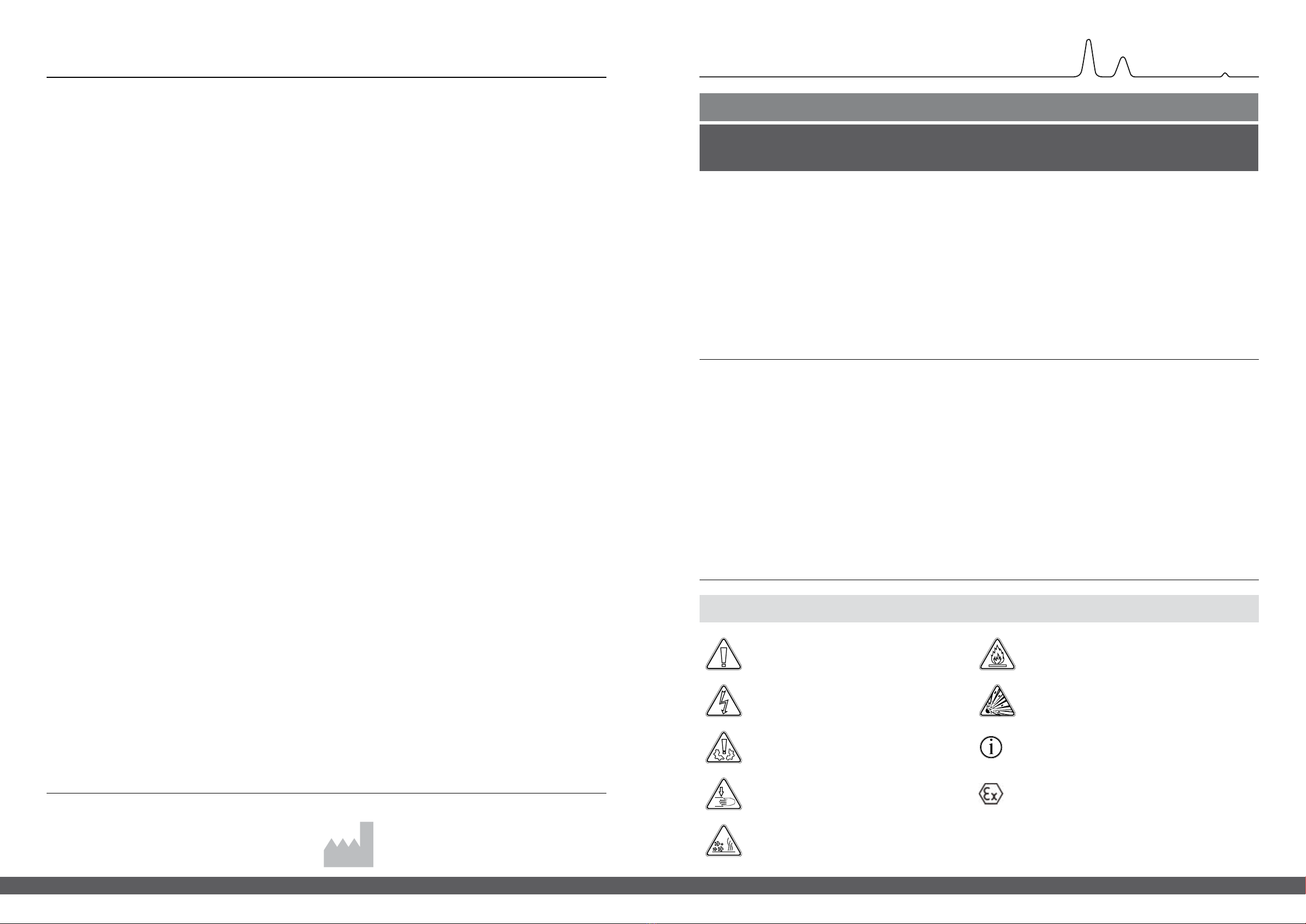
Symbols used throughout the instructions for use
Info
Risk of burning/freezing
Risk of personal injury
Risk of material damage
Risk of electric shock
Hazard Risk of re/ammable materials
Risk of explosion/explosive materials
ATEX information
Intended use
BioCompact II refrigerators (RR) and freezers (RF) are designed and manufactured to provide safe and precise conditions
for the items stored. The cabinets are designed for the following operating ranges:
RR +2/+20 °C
RF -25/-5 °C
At the maximum ambient temperature speciced in this instructions for use, and a maximum relative humidity of 70%.
The user must ensure that the cabinet is used in accordance with its intended use.
Abnormal use or use conicting with the intended use or guidelines stipulated in the product documentation can lead to:
danger to patient safety, damage to stored items, damage to cabinet, danger to user.
Gram BioLine equipment is designed to be used in a system with monitored additional independent alarms to ensure
timely reaction to alarms and thereby maximum item safety.
Quick guide – BioCompact II ..............................2
Table of Content ........................................4
Before you proceed . . . . . . . . . . . . . . . . . . . . . . . . . . . . . . . . . . . . . . 5
Symbols used throughout the instructions for use ..........5
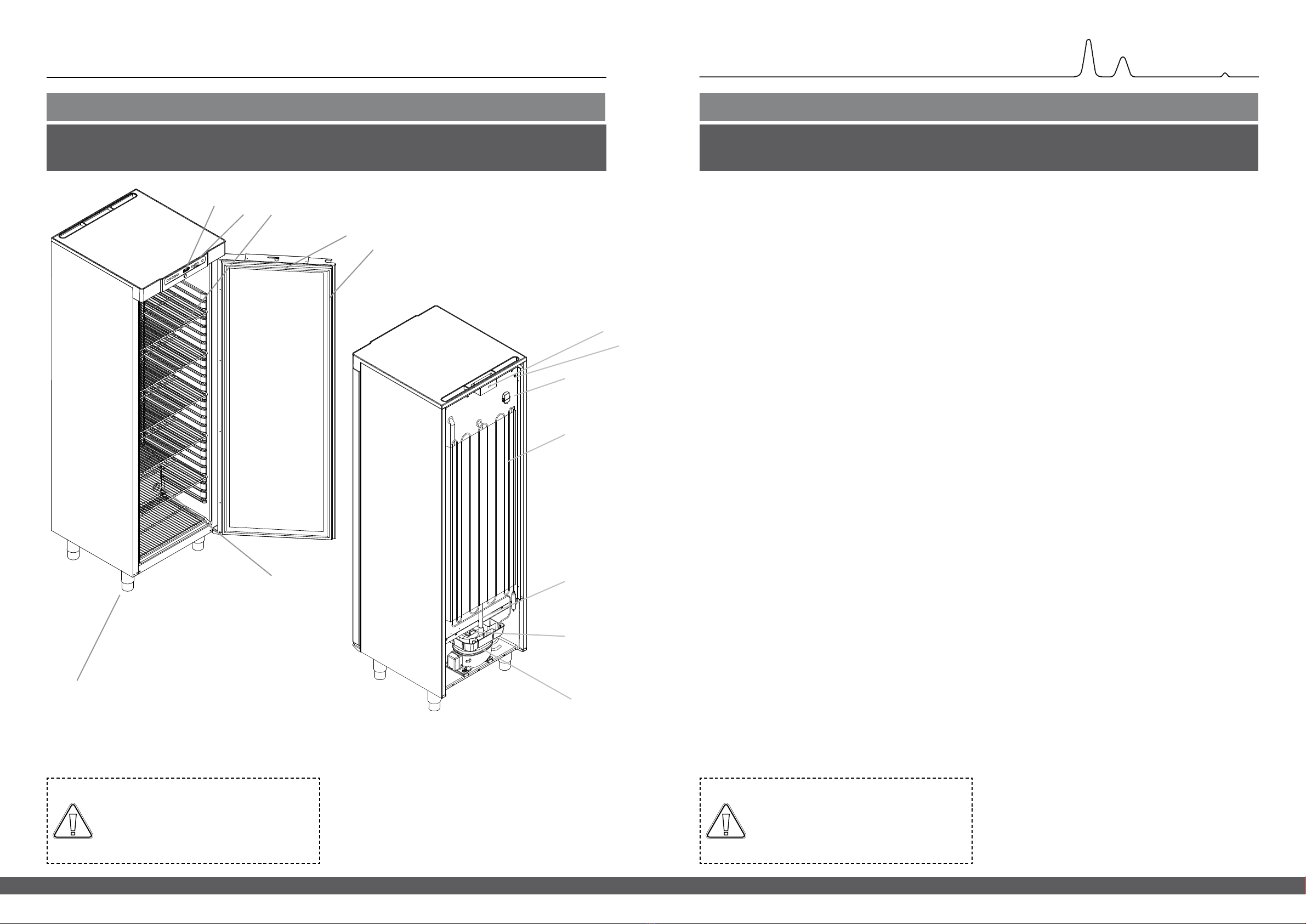
Cabinet components.....................................6
BioCompact II 210, 310, 410, 210/210, 310/210...............6
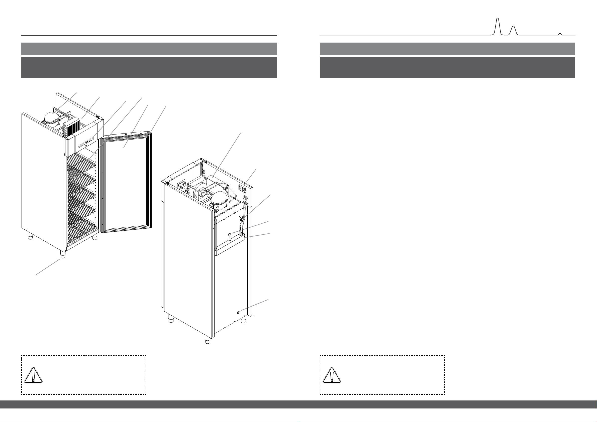
BioCompact II 610 .......................................8
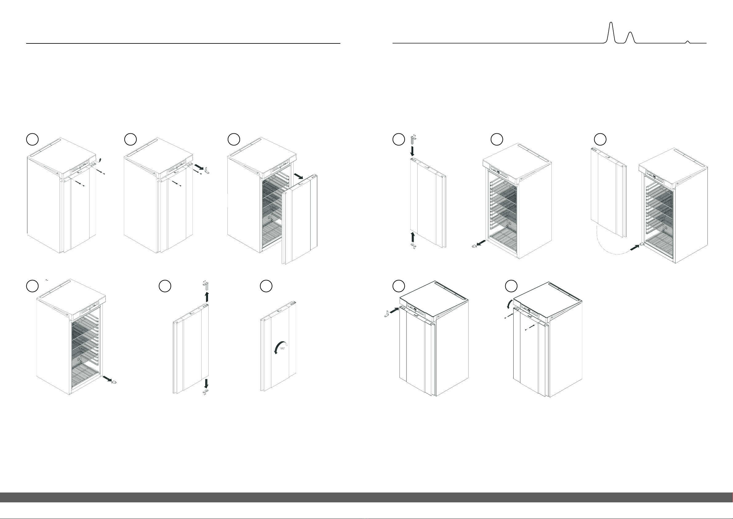
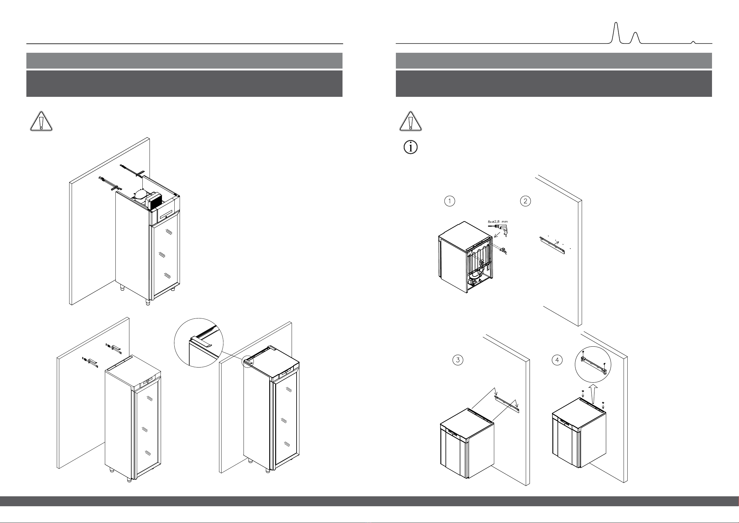
Installation ............................................10
Initial setup steps .......................................10
Anti tilt bracket .........................................16
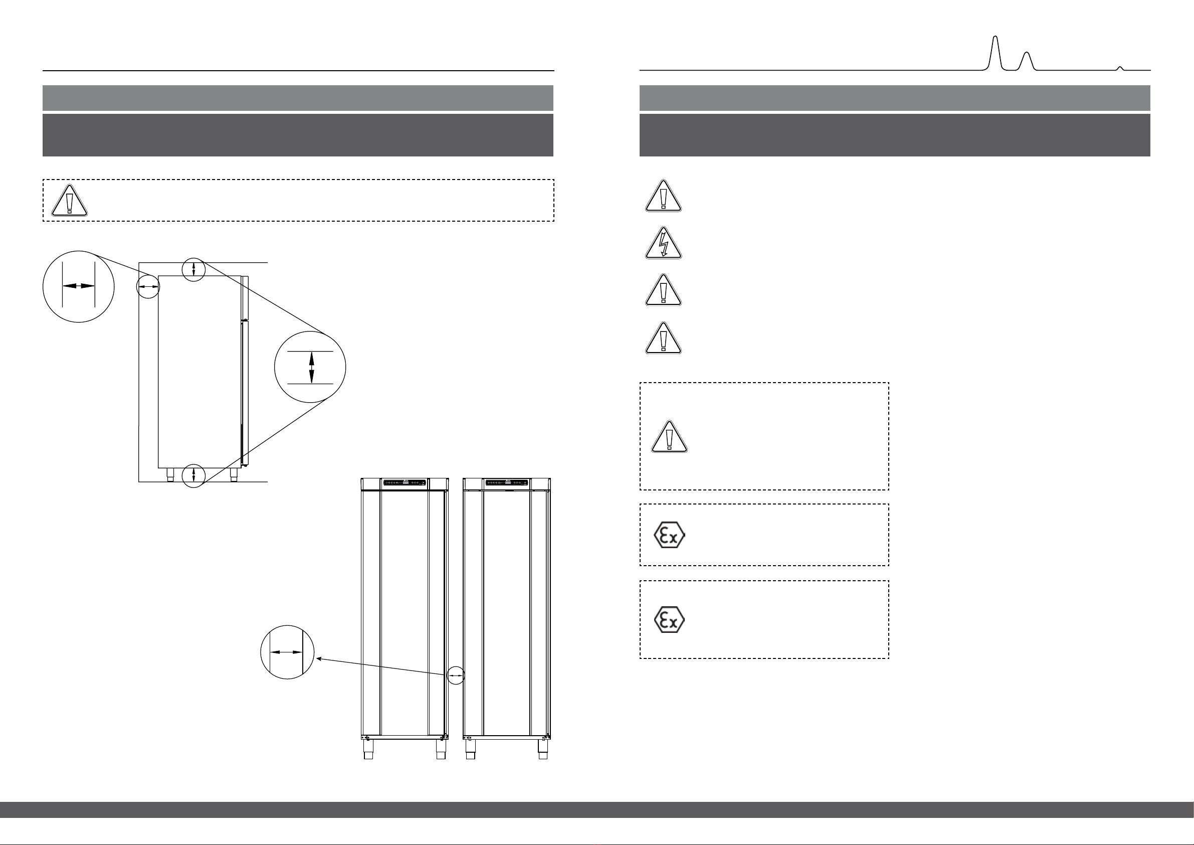
Surroundings ..........................................18
Voltage free contact .....................................20
Connection to power ....................................22
Equipotential bonding ...................................24
Start-up ...............................................27
The digital display.......................................27
Walkthrough of menu ...................................28
Error codes ............................................29
Local alarm settings ....................................30
Local high alarm .......................................30
Local low alarm.........................................30
Local alarm settings .....................................31
On/o local door alarm .................................32
Delay for local door alarm................................32
Local acoustic settings ...................................33
External alarm settings .................................34
External high alarm .....................................34
External low alarm ......................................34
External high alarm delay ................................35
External low alarm delay .................................35
On/o external door ....................................36
External
door alarm delay alarm ..........................36
External acoustic settings ................................37
Parameter settings .....................................38
Sensor oset ...........................................38
Escorted/set alarm limits.................................40
Defrosts/24 hours ......................................41
Display sensor..........................................42
Electric low temperature protection .......................43
Ordinary use...........................................44
Regular maintenance ..................................46
Cleaning ...............................................46
Door gasket ............................................47
General info ...........................................48
Service ................................................48
Type/number plate. . . . . . . . . . . . . . . . . . . . . . . . . . . . . . . . . . . . . . 49
Defrost water ..........................................50
Access port ............................................51
Important..............................................52
Disposal ...............................................53
Datasheet .............................................54
BioCompact II 210, 310, 410, 210/210, 310/210 ................54
BioCompact II RR210H...................................55
BioCompact II RR310H...................................56
BioCompact II RR410H...................................57
BioCompact II RF210H ..................................58
BioCompact II RF310H ...................................58
BioCompact II RF410H ...................................59
BioCompact II RR210/RR210H ............................60
BioCompact II RR210/RF210H.............................61
BioCompact II RF210/RF210H.............................62
BioCompact II RR310/RF210H.............................63
BioCompact II RR210G...................................64
BioCompact II RR310G...................................65
BioCompact II RR410G...................................66
BioCompact II RF210G ..................................67
BioCompact II RF310G ...................................67
BioCompact II RF410G ...................................68
BioCompact II RR210/RR210G ............................69
BioCompact II RR210/RF210G.............................70
BioCompact II RF210/RF210G.............................71
BioCompact II RR310/RF210G.............................72
BioCompact II RR610H...................................74
BioCompact II RF610H ...................................75
BioCompact II RR610G...................................77
BioCompact II RF610G ...................................78
Declaration of conformity ..............................80
BioCompact II 210, 310, 410, 210/210 & 310/210 ............80
BioCompact II 610 ......................................81
BioCompact II 210, 310, 410, 210/210 & 310/210 –
Accessories code 69 .....................................82
BioCompact II 610 –
Accessories code 69 .....................................83
Wiring diagram ........................................84
BioCompact II 210/310/410 ..............................84
BioCompact II 210/310/410 - with LTP .....................85
BioCompact II RR610 – with solid door .....................86
BioCompact II RF610 ....................................87
BioCompact II RR610 – with glass door.....................88
BioCompact II RR610 – with solid door, with LTP ............89
BioCompact II RR610 – with glass door, with LTP ............90
Piping diagram ........................................91
BioCompact II ..........................................91
IQ & OQ ...............................................92
Installation Qualication .................................92
Operation Qualication ..................................92
PQ ..................................................100
Performance Qualication ..............................100