manuals.online logo
Brands
  1. Home
  2. •
  3. Brands
  4. •
  5. GRAUPNER
  6. •
  7. Toy
  8. •
  9. GRAUPNER STARLET Instruction Manual

GRAUPNER STARLET Instruction Manual

Other GRAUPNER Toy manuals

GRAUPNER DANDY ARTF RC User manual

GRAUPNER

GRAUPNER DANDY ARTF RC User manual

GRAUPNER Twister User manual

GRAUPNER

GRAUPNER Twister User manual

GRAUPNER Seenotrettungsboot User manual

GRAUPNER

GRAUPNER Seenotrettungsboot User manual

GRAUPNER MEGA DRAGSTAR III User manual

GRAUPNER

GRAUPNER MEGA DRAGSTAR III User manual

GRAUPNER CLUB STAR II User manual

GRAUPNER

GRAUPNER CLUB STAR II User manual

GRAUPNER RANZOW Instruction Manual

GRAUPNER

GRAUPNER RANZOW Instruction Manual

GRAUPNER jodel robin dr 400/18 User manual

GRAUPNER

GRAUPNER jodel robin dr 400/18 User manual

GRAUPNER LANCAIR Instruction Manual

GRAUPNER

GRAUPNER LANCAIR Instruction Manual

GRAUPNER BISMARCK User manual

GRAUPNER

GRAUPNER BISMARCK User manual

GRAUPNER PITTS S12 Instruction Manual

GRAUPNER

GRAUPNER PITTS S12 Instruction Manual

GRAUPNER KWIK FLY MK 3 User manual

GRAUPNER

GRAUPNER KWIK FLY MK 3 User manual

GRAUPNER EPIC Victory S User manual

GRAUPNER

GRAUPNER EPIC Victory S User manual

GRAUPNER ELEKTRO-UHU Instruction Manual

GRAUPNER

GRAUPNER ELEKTRO-UHU Instruction Manual

GRAUPNER BELLANCA User manual

GRAUPNER

GRAUPNER BELLANCA User manual

GRAUPNER U-16 EMDEN User manual

GRAUPNER

GRAUPNER U-16 EMDEN User manual

GRAUPNER alpina 400i elektro 61797 User manual

GRAUPNER

GRAUPNER alpina 400i elektro 61797 User manual

GRAUPNER Theodor Heuss User manual

GRAUPNER

GRAUPNER Theodor Heuss User manual

GRAUPNER 65 User manual

GRAUPNER

GRAUPNER 65 User manual

GRAUPNER WILGA 2000 User manual

GRAUPNER

GRAUPNER WILGA 2000 User manual

GRAUPNER ALPINA 3001 CHAMP PRO User manual

GRAUPNER

GRAUPNER ALPINA 3001 CHAMP PRO User manual

GRAUPNER 4469.400 User manual

GRAUPNER

GRAUPNER 4469.400 User manual

GRAUPNER GL-39 ALBATROS User manual

GRAUPNER

GRAUPNER GL-39 ALBATROS User manual

GRAUPNER FOCKE WULF 190 D User manual

GRAUPNER

GRAUPNER FOCKE WULF 190 D User manual

GRAUPNER Premium LINE User manual

GRAUPNER

GRAUPNER Premium LINE User manual

Popular Toy manuals by other brands

FUTABA GY470 instruction manual

FUTABA

FUTABA GY470 instruction manual

LEGO 41116 manual

LEGO

LEGO 41116 manual

Fisher-Price ColorMe Flowerz Bouquet Maker P9692 instruction sheet

Fisher-Price

Fisher-Price ColorMe Flowerz Bouquet Maker P9692 instruction sheet

Little Tikes LITTLE HANDIWORKER 0920 Assembly instructions

Little Tikes

Little Tikes LITTLE HANDIWORKER 0920 Assembly instructions

Eduard EF-2000 Two-seater exterior Assembly instructions

Eduard

Eduard EF-2000 Two-seater exterior Assembly instructions

USA Trains EXTENDED VISION CABOOSE instructions

USA Trains

USA Trains EXTENDED VISION CABOOSE instructions

Modellbau Laffont Z1601 Assembly instructions

Modellbau Laffont

Modellbau Laffont Z1601 Assembly instructions

NOCH 12905 instruction manual

NOCH

NOCH 12905 instruction manual

Eduard Ki-61-Id quick start guide

Eduard

Eduard Ki-61-Id quick start guide

Viessmann Vollmer 45616 Mounting instruction

Viessmann

Viessmann Vollmer 45616 Mounting instruction

Vollmer 42004 Mounting instruction

Vollmer

Vollmer 42004 Mounting instruction

Phoenix Model CLASSIC-EP instruction manual

Phoenix Model

Phoenix Model CLASSIC-EP instruction manual

H-KING Sopwith Camel British WW1 Fighter instruction manual

H-KING

H-KING Sopwith Camel British WW1 Fighter instruction manual

MODSTER Predator 4x4 Crawler user manual

MODSTER

MODSTER Predator 4x4 Crawler user manual

DHK Hobby 8136 User instruction manual

DHK Hobby

DHK Hobby 8136 User instruction manual

THUNDER TIGER Raptor 50 V2 kit manual

THUNDER TIGER

THUNDER TIGER Raptor 50 V2 kit manual

Timberkits Skateboarder instructions

Timberkits

Timberkits Skateboarder instructions

Hangar 9 Funtana 125 Assembly manual

Hangar 9

Hangar 9 Funtana 125 Assembly manual

manuals.online logo
manuals.online logoBrands
  • About & Mission
  • Contact us
  • Privacy Policy
  • Terms and Conditions

Copyright 2025 Manuals.Online. All Rights Reserved.

GRAUPNER GmbH & Co. KG D-73230 KIRCHHEIM/TECK GERMANY
Modifications reserved. No liability for printing errors. 08/2011
- 1 -
Order No. 9353
BUILDING INSTRUCTIONS
STARLET
RC electric model for three 650 mAh LiPo cells
This model requires a four-function HoTT radio control system
GRAUPNER GmbH & Co. KG D-73230 KIRCHHEIM/TECK GERMANY
Modifications reserved. No liability for printing errors. 08/2011
- 2 -
Please be sure to read through the Safety Notes in the Appendix to these operating instruc-
tions. If you ever dispose of the model, it is important to pass on the complete building instruc-
tions to the new owner.
Introduction
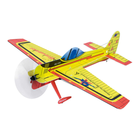
The STARLET is an attractive electric-powered RC model aircraft which is easy to
transport thanks to its compact dimensions. However, do not let its small size deceive
you: the model requires some prior modelling experience if you are to assemble and
operate it successfully. The aeroplane is highly pre-fabricated, but the work which
you have to carry out is important, and must be done carefully. The model will only be
strong and fly well if you complete your tasks competently. The all-up weight must
not exceed 550 g.
RC system accessories (not included)
The following items are required to complete and fly the model.
GRAUPNER MX-12 HoTT 2.4 GHz COMPUTER SYSTEM Order No.33112
Transmitter charge lead Order No.3022
COMPACT 260Z brushless motor Order No.7731
Spinner, 28 mm Ø Order No.7731.1
CAM SLIM PROP, 17 x 7.5 cm Order No.1372.17.7,5
BRUSHLESS CONTROL 8 speed controller Order No.7231
LiPo 3/650 flight battery, 11.1 V / 0.65 Ah Order No.7609.3
Charge lead with BEC connector Order No.3037
ULTRAMAT 16 S battery charger Order No.6468
DES 427 BB servo (four required) Order No. 7910
Servo extension lead, 100 mm (two required) Order No.3935.11
Servo extension lead, 180 mm (two required) Order No.3935.18
Essential tools and adhesives (not included)
Balsa knife Order No.980
Cyano-acrylate (“cyano”) Order No.5821
Cyano activator Order No.953.150
UHU ALLESKLEBER Kraft Order No.1096
You will also need the following items: cross-point screwdriver, 8 mm A/F open-
ended spanner, flat-nose pliers, side-cutters, 1.0, 1.6, 2.2 and 3.0 mm Ø drill bits, 1.5,
2.0 and 2.5 mm A/F allen keys, soldering iron and solder, heat-gun, glasspaper, set-
square, spirit felt-tip pen, adhesive tape, paper towel, rubber gloves, protective gog-
gles.
Building instructions
Please read right through these building instructions before you start construction, so
that you have a clear understanding of the sequence of assembly. Before you start
on a particular stage, make sure you have all the requisite components, tools and
adhesives to hand. When assembling the model always work on a clean, smooth, flat
surface, or on a workbench with a foam overlay. Unless stated otherwise, use cyano
adhesive with activator for all joints on this model. The best method is to apply cyano
to one surface, then spray the opposite face with activator. Ensure that excess glue
does not get onto your hands or the model’s finished surfaces. Wipe off excess glue
immediately using a piece of paper towel.
GRAUPNER GmbH & Co. KG D-73230 KIRCHHEIM/TECK GERMANY
Modifications reserved. No liability for printing errors. 08/2011
- 3 -
Caution: never allow cyano to come into contact with any part of your body,
and especially not your eyes. For this reason we recommend that you wear
goggles when using these materials. Store the adhesive well out of the reach of
children. For safety reasons we recommend that you only use the adhesive
stated above. Be sure to read the operating instructions and safety notes sup-
plied with all the accessory items used in the model.
The wing
First secure the aileron hinges, which are already in place in the wings, using UHU
ALLESKLEBER Kraft adhesive. Let the glue set hard, then push the ailerons onto the
projecting hinges, leaving an even gap about 1 mm wide along the hinge line.
Unscrew the servo well cover from the wing, and check that the aileron servo fits.
Cut off the superfluous arms from the servo output device, and drill out the outer hole
in the remaining arm to 1.6 mm Ø. Set the servo to neutral (centre) from the trans-
mitter, then push the output lever onto the shaft at right-angles to the case sides
before fitting the retaining screw. Fix the servo to the mounting blocks with a drop of
cyano at each mounting lug. Repeat the procedure with the second aileron servo.
Connect the servo extension leads to the servo leads, and carefully draw the cables
through the wing using the thread which you will find inside the structure. Place the
servo well covers in the wing and secure them with the retaining screws. Complete
the aileron pushrods as shown, connect the linkages, then glue the aileron horns in
the slots.
GRAUPNER GmbH & Co. KG D-73230 KIRCHHEIM/TECK GERMANY
Modifications reserved. No liability for printing errors. 08/2011
- 4 -
This picture shows the completed aileron linkage. Please note that the servo output
arm should be at least 12 mm long, otherwise the clevis will foul the wing surface.
The photo shows the servo extension lead projecting out of the underside of the
wing. Note that the lead should first be run straight out of the opening in the root rib,
and then doubled-back to pass through the hole in the underside. Carefully open up
the hole in the wing using a sharp balsa knife.
The fuselage and tail
Attach the propeller driver, the cruciform mount and the retaining collet to the motor;
you will find these parts in the pack of Order No. 7731.
The picture shows the component parts of the propeller driver and motor mount; take
care to tighten all the screws fully.
This picture shows the motor with the cruciform mount and the propeller driver fitted.
Cut the motor wires to length, and strip the ends for a length of about 5 mm. Slip
separate pieces of heat-shrink sleeve (included in Order No. 7731) over the three
wires. Tin all the bare wire ends before soldering the pairs together in any order. Slip
GRAUPNER GmbH & Co. KG D-73230 KIRCHHEIM/TECK GERMANY
Modifications reserved. No liability for printing errors. 08/2011
- 5 -
the heat-shrink sleeves temporarily over the soldered joints (don’t shrink them), and
carry out a check of the motor function: the motor should spin clockwise (to the right)
as seen from the tail, looking forward. If not, swap over any two of the soldered joints,
and only then use a heat-gun to shrink the sleeves over the soldered joints.
Fix the motor to the firewall using four 3 Ø x 10 mm self-tapping screws (supplied
with the motor). Place the cowl on the fuselage, then slip the spinner backplate on
the propeller driver. At this point you can adjust the position of the motor using the
variable firewall until the spinner lines up correctly with the front of the cowl.
When you are confident that everything fits, drill 2.2 mm Ø pilot-holes in the cowl
before attaching the moulding to the fuselage using three 2.2 Ø x 6.5 mm self-
tapping screws. The position of the bottom two screws can be seen in a later picture;
please refer to the section entitled “The undercarriage”.
GRAUPNER GmbH & Co. KG D-73230 KIRCHHEIM/TECK GERMANY
Modifications reserved. No liability for printing errors. 08/2011
- 6 -
Use your fingertips to locate the openings for the wing cabane under the covering
film, and cut away the film with a balsa knife. Secure the cabane on both sides by
tightening the M3 x 8 socket-head screws; the holes can later be covered with pieces
of the coloured adhesive tape supplied in the accessory pack.
The elevator and rudder servos can now be prepared for installation by drilling out
the output arms to 1.0 mm Ø and pressing the rubber grommets and tubular metal
spacers into the mounting lugs; the flange of the spacers should be on the underside.
The servo mounting components are supplied in the servo accessory pack.
This picture shows the servos installed in the servo plate, one with the pushrod
connected, one ready to be connected. Unscrew the output levers to allow the push-
GRAUPNER GmbH & Co. KG D-73230 KIRCHHEIM/TECK GERMANY
Modifications reserved. No liability for printing errors. 08/2011
- 7 -
rods to be engaged. The picture also shows the 10 x 6 mm opening in the fuselage
turtle deck for the aileron servo extension leads.
Glue the elevator and rudder hinges in place using UHU ALLESKLEBER Kraft,
following the principle described earlier; glue the elevator joiner in both elevators at
the same time, using cyano.
Accurately mark the centreline of the tailplane using a setsquare and a spirit felt-tip
pen, then mark on it the outlines of the joint surface for the fuselage and the fin. Melt
the covering film along the marked lines using the tip of a hot soldering iron, and peel
off the unwanted film. Glue the tailplane to the fuselage, keeping it exactly central
and “square”. Cut a slit in the fuselage to accept the bottom rudder hinge, then glue
the fin to the tailplane and fuselage, again keeping it exactly central and vertical.
GRAUPNER GmbH & Co. KG D-73230 KIRCHHEIM/TECK GERMANY
Modifications reserved. No liability for printing errors. 08/2011
- 8 -
Bend the tail end of the rudder and elevator pushrods at right-angles using flat-nose
pliers, and snip off the excess length. Fit the horns on the pushrods, then glue the
horns in the rudder and elevator.
The undercarriage
Push the two undercarriage legs into the holes and slots on the underside of the
fuselage, and secure them with the plastic saddle clamps as shown in the picture.
This photo shows the parts required to mount the wheels and wheel spats on the
undercarriage legs. Drill a 3.0 mm Ø hole in each wheel spat as shown in the picture.
Now fit the wheel spat, a collet, the wheel and a second collet onto the wheel axle,
keeping exactly to this sequence. Position the parts accurately, and glue the spat in
place. Take care that no adhesive gets into the wheel hubs, as this would prevent
them rotating.
The picture shows one wheel spat glued to the undercarriage leg, and the strut
fairing with mounting brackets. Sand the joint surface of the brackets before gluing
them in place, after removing the film over the joint area of the strut fairing.
GRAUPNER GmbH & Co. KG D-73230 KIRCHHEIM/TECK GERMANY
Modifications reserved. No liability for printing errors. 08/2011
- 9 -
The picture shows the completed undercarriage and the wing, secured to the cabane
using four M3 x 6 pan-head screws. The pilot and windscreen have also been in-
stalled in this shot.
If you wish, you can screw the wing struts in place at this point, as shown in the
photo; these parts are only decorative, and are not required for airframe strength.
Please note that the struts are handed, i.e. the left and right struts are different.
Installing the HoTT receiver and the LiPo battery
The first step is to connect the servo leads to the receiver; we recommend the fol-
lowing socket sequence: socket 2: left aileron servo; socket 3: elevator servo; socket
4: rudder servo, socket 5: right aileron servo; socket 6: speed controller. It is a good
GRAUPNER GmbH & Co. KG D-73230 KIRCHHEIM/TECK GERMANY
Modifications reserved. No liability for printing errors. 08/2011
- 10 -
idea to connect 100 mm servo extension leads to sockets 2 and 5 permanently, as
this makes it much easier to connect the aileron servos when you rig the aeroplane.
At this point you should carry out a check of all the working systems, with the RC
system transmitter switched on. Please bear in mind that the motor could burst into
life when you first connect the BEC plug and socket, so remember to remove the pro-
peller before switching on for the first time.
Control surface travels
The following control surface travels are our recommended starting point, but you
may wish to adjust them to suit your personal preference: ailerons 16 mm up and 8
mm down; elevators 15 mm to both sides of neutral; rudder 22 mm to both sides.
Balancing
Assemble the model completely, ready to fly, i.e. with the LiPo flight battery in place.
The Centre of Gravity range is 60 mm to 70 mm aft of the wing root leading edge,
measured at the centre of the wing. You can set the correct CG by adjusting the
position of the LiPo battery. Support the model at the stated CG position with two
fingers under the wing roots, and allow it to hang freely: when balanced correctly, the
fuselage will hang level.
Flying
For the initial test-flight wait for a day with very little or no wind, and assemble the
model completely. Check that all control surfaces are at neutral. For a successful
take-off from the ground a smooth, level strip pointing directly into wind is ideal. If
your runway is not of that quality, switch the motor on, and give the aeroplane a
hand-launch directly into any breeze; trotting forward for a few steps gains the neces-
sary momentum. Initially use the aileron and elevator controls gently, just to correct
any deviations from a straight flight path. Fine-tuning can be carried out by adjusting
the trim sliders situated below and adjacent to the transmitter sticks. Always land the
model directly into wind, with the motor throttled back. Just before touch-down, apply
slight up-elevator to flare out and slow the machine down further. It is essential al-
ways to land straight into wind.
All of us at GRAUPNER Modellbau wish you many fine flights with your new
STARLET
The prototype: a full-size STARLET, built in 1980