795-92305
03/10
Graymills Corporation – 3705 N. Lincoln Ave – Chicago, IL 60613 – USA – 877.INK.PUMP – www.g
2
•Never work with equipment you feel may be unsafe. Contact your supervisor immediately if you feel a piece of equipment
is in an unsafe condition.
•We strongly recommend all electrical installations include a Ground Fault Interrupter (GFI).
•Failure to permanently ground the unit and controls before connecting to electrical power can cause shock, burns or
death.
•Install ground and wiring according to local and national electrical code requirements.
•Install a fused disconnect switch on all power legs near the unit
•Disconnect and lockout electrical supply before installing or servicing unit.
•Unit must be properly grounded to prevent electric shock hazard. Connect only to three-prong outlet. Should cord become cracked,
frayed or damaged in any way, it should be repaired or replaced immediately by a qualified electrician. Never use an extension
cord.
•Before doing any maintenance work, disconnect electrical power or air supply.
•Do not attempt to repair electrical components. Direct all electrical repair questions to the factory.
•Do not allow liquids to come in contact with the internal electrical components of the controller. This could result in injury to the
operator, or damage to the unit.
OPERATING VOLTAGES
Non-Explosion Proof Chillters:
Chillter-A: 115 VAC 60 Hz 1 Phase
Chillter-B: 230 VAC 50/60 Hz 1 Phase
OPERATING PRESSURE
Do not exceed 30 psi on chilled fluid (non-ink) supply.
ABOUT CHILLTERS™
Graymills’ CHILLTER™ systems are designed to keep ink at the desired temperature. To do so, the CHILLTER™ system combines a
heat-exchanging ink filter with an electronic controller. The controller measures the temperature of the ink and opens and closes valves
to release chilled water into the main CHILLTER™ body. The CHILLTER™ can also be used to heat ink, if desired, by using heated
water in the system. (Changing some settings would be required.)
INSTALLING CHILLTERS™
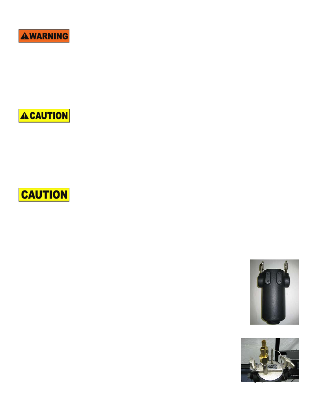
a) Install CHILLTER™ Filter Body
•Ink enters the CHILLTER™ filter through the bottom port and exits through one or both, as needed, of
the top ports. Graymills recommends the use of full-port quick connect fittings – contact your local
representative.
•Filter can be mounted by attaching bottom port to rigid NPT pipe on the discharge of your ink pump or
by bolting to a flange via four bolt holes on back.
•Install filter cartridge, set lid on filter body, and firmly tighten both thumb nuts.
b) Install CHILLTER™ Controller
•The CHILLTER™ controller mounts via four bolt holes on the back of the unit.
•The CHILLTER™ controller may be bolted to any vertical surface via the bolt holes.
•If the CHILLTER™ filter is mounted on a pipe, the CHILLTER™ controller may be attached to the
filter body. Screw four bolts into threaded holes on the filter body and slide controller onto the body.
•Check fuses in Power Inlet Module located next to plug receptacle.
•Using provided power cable, attach female end to receptacle on controller.
•Plug in unit and flip switch on Power Inlet Module to ON (I).
c) Run Ink Lines
raymills.com
•If the filter is not attached to a rigid NPT pipe, connect the entry port on the bottom to the
discharge of your ink pump.
•Connect one of the outlet ports to the inlet on your ink chamber or pan.
•The unused port may be used for bypass-style viscosity controls, bypass systems for flow
control, or may be blocked off with included plug.


