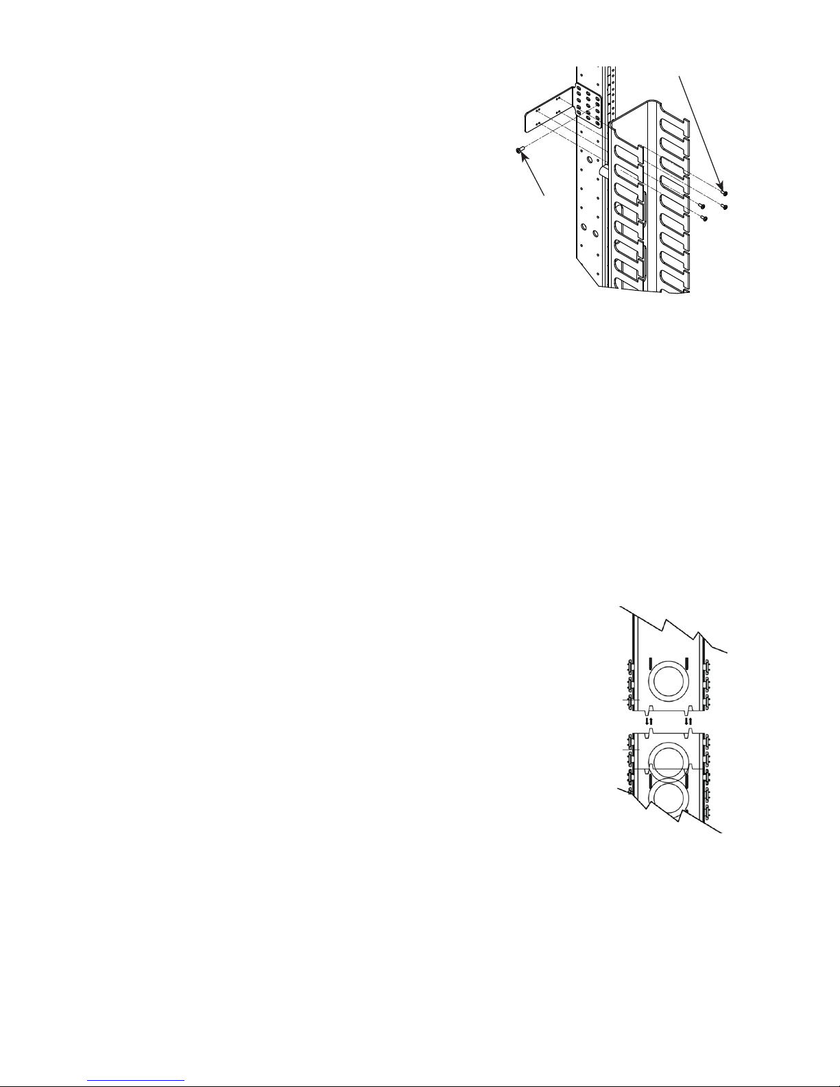
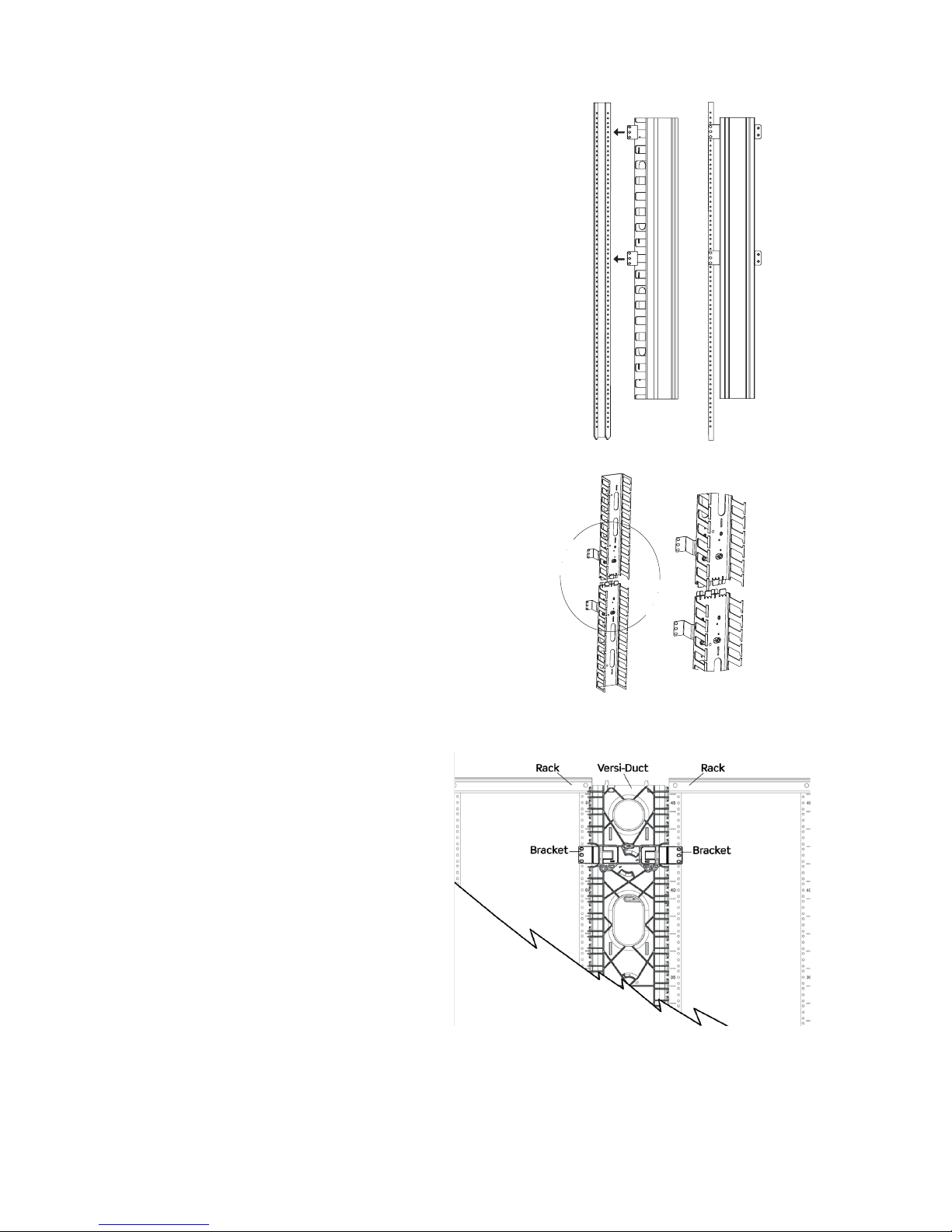
Great Lakes Case & Cabinet VCM5-FR User manual

VCM5-FR, VCM5-FO
5" Vertical Cable Management & Accessories
Installation Instructions
1.866.TRY.GLCC (879-4522)
WeRackYourWorld.com

2
PREFACE
This manual is provided to prevent service personnel from committing an act
that results in the risk of re, electric shock, or injury to persons. Only trained
service personnel should receive, unpack, and assemble the Vertical Cable
Manager (VCM). In addition, only trained service personnel should manage
cables in the VCM.
SAFETY SYMBOLS USED IN THIS MANUAL
This manual provides general safety guidelines to be observed during
installation, operation, and maintenance of the VCMs.
WARNING:
Failure to follow directions in the warning could result in injury to persons or
loss of life.
Improper handling and use of the VCM could result in equipment damage,
serious injury, or possible death.
Only UL® Listed ITE (Information Technology Equipment) cable should be
managed with the VCM.
Be sure to read and follow all individual manufacturer equipment manuals for
safety and installation instructions.
Proper spacing is required when installing electrical equipment to avoid
electrical shock.
5" VERTICAL CABLE MANAGER
MOUNTING BRACKETS
There are two sets of 4 brackets that will allow you to mount the
cable management channels in multiple ways. Each bracket set
is compatible with different racks - ensure that the brackets that
are being used are the correct brackets for the rack. In addition,
bracket sets will allow VCMs to be mounted to the front or back
of rack uprights; however, some racks can only accept mounting
to the front of the upright.
PARTS LIST: VCM5-FO & VCM5-FR
COMPONENTS AND QUANTITIES ARE THE SAME FOR
VCM5-FO AND VCM5-FR, EXCEPT WHERE SPECIFIED
COMPONENT QTY.
VCM5-FO CHANNEL OR VCM5-FR CHANNEL 2
5" CHANNEL COVERS VCM5-FO: 2; VCM5-FR:4
BRACKET SET “A1” (BRACKETS ARE INSTALLED ON CHANNEL BY DEFAULT) 4
BRACKET SET “A2” 4
#12-24 SCREWS 8
#8-32 X 1/2" SCREWS 16
INSTRUCTION MANUAL 1
TOOLS REQUIRED: 3/8" NUT DRIVER, PHILLIPS HEAD SCREWDRIVER

3
BRACKET SET A1
COMPATIBILITY:
Bracket Set A1 is compatible with the following Great Lakes
racks:
GLRR-1984**(VCM can mount to the front or back side of upright)
4P1224-** (VCM can mount to the front or back side of upright)
4PM6-** (VCM must mount to front of upright)
4PHD29 (VCM must mount to front of upright)
MOUNTING BRACKET SET A1 MOUNTED TO THE FRONT
OF THE UPRIGHT
MOUNTING BRACKET SET A1 MOUNTED TO THE BACK
OF THE UPRIGHT
DETAIL A
DETAIL B
A
B
5.19
5.44
2.946.56
DETAIL A
DETAIL B
A
B
5.19
5.44
2.946.56
DETAIL A
DETAIL B
A
B
5.44
5.19
.93
2.94
DETAIL A
DETAIL B
A
B
5.44
5.19
.93
2.94

4
MOUNTING BETWEEN
TWO RACKS
When center mounting the
VCM5 between any two of
the A1 compatible racks, a
second set of A1 Brackets
should
be used, so that there
are 4 brackets installed on
the left and right side of
the channel. Optional Part
No. VCM5-BKT, consists of
4, A1 brackets and should
be used with center mount
applications.
1. Align the channel mounting
brackets with the equipment rack
(Figure 1).
2. To secure the channel in place,
push the supplied #12-24 screws
through the mounting bracket and
screw into the equipment rack.
3. When assembling the 80”
channel, carefully align the
connecting tabs (Figure 2).
4. To install the cover(s), t the
cover over one side of duct ngers
and rotate the cover to the other side
until it snaps into place.
NOTE: The channel ngers can
be bent outward and snapped off
to more easily run cables from the
vertical to the horizontal channel.
INSTRUCTIONS FOR BRACKET SET A1
FIGURE 1
FIGURE 2

5
Bracket set A2 is compatible
with the following
Great Lakes racks:
VD4PM6-2436
VD4P1224-2436
VD4PHD-2436
CMR-45U16
CMR-45U
MOUNTING BRACKET SET A2 TOWARDS THE BACK
OF THE UPRIGHT
MOUNTING BRACKET SET A2 TOWARDS THE FRONT
OF THE UPRIGHT
BRACKET SET A2
DETAIL A
DETAIL A
DETAIL A
A A
VCM5
5.13
5.44
5.13
.19SHOWN AT
EXTENDS TO 2.19
3.09SHOWN AT
RECESS TO 5.09
.93
2.944
4.06SHOWN AT
EXTENDS TO 6.06
.79SHOWN AT
RECESS TO -2.79
5.23
5.23
5.19
DETAIL A
DETAIL A
DETAIL A
A A
VCM5
5.13
5.44
5.13
.19SHOWN AT
EXTENDS TO 2.19
3.09SHOWN AT
RECESS TO 5.09
.93
2.944
4.06SHOWN AT
EXTENDS TO 6.06
.79SHOWN AT
RECESS TO -2.79
5.23
5.23
5.19

6
FIGURE 4
FIGURE 3
VCM
VCM
INSTRUCTIONS FOR BRACKET SET A2
1. Remove bracket set A1. Based on
the rack that is being used, determine
if the VCM will mount to the front or
rear of the upright. Front or rear mounting
will determine correct orientation of
bracket set A2 (see page 5 for details).
Once orientation is determined, secure the
brackets (2 per each 40" section) to the VCM
by using the supplied #8-32 screws (Figure 3).
Verify bracket is securely fastened into place.
NOTE: All provided brackets must be installed
on the same side of the channel.
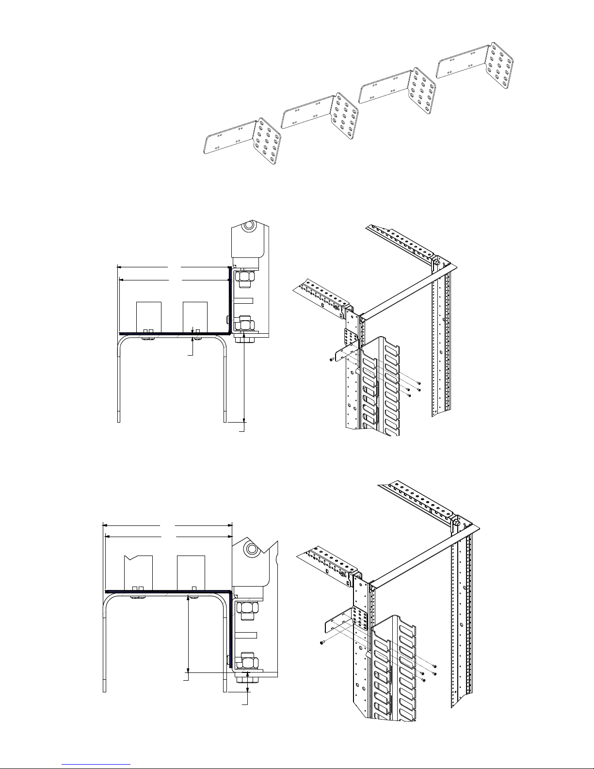
2. Hold the first channel section in the desired location of the
equipment rack, align the bracket to the appropriate mounting
holes located on either the front/back side of the rack.
3. To secure the channel section, screw the supplied #12-24
screws through the mounting bracket into the desired holes in the
equipment rack and tighten.
NOTE: Use cage nut hardware supplied with your square hole
uprights for those applications.
4. To mount the second section, carefully align the
tabs on the two sections (Figure 4) and attach
to the upright.
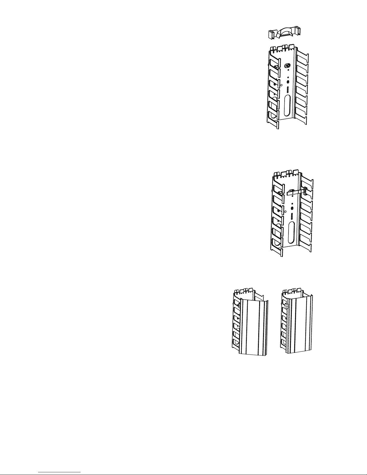
5. Snap the supplied covers on the
pre-determined fingers for cable security and
to maintain a clean installation.
NOTE: The channel ngers can be bent outward
and snapped off to more easily run cables from the
vertical to the horizontal channel.
OPTIONAL MOUNTING:
Connect the top and bottom of the cable management section.
Install all 4 mounting brackets. Next hold up to rack and pencil
mark the holes you need to secure VCM5F* to rack. Remove the
brackets and install them unto the rack. Finally attach to cable
management to rack by using #12-24 screws.
#12-24
#8-32

7
OPTIONAL ACCESSORIES
Slack Spool VCM5-SL
The Slack Loop Storage Organizer manages and
stores excess cable for future use. The Organizer
is moveable and can be installed to accommodate
different size slack loops.
1. Slide the Slack Loop Storage Organizer
over the ngers of the Vertical Slotted Duct
(Figure 5).
NOTE: Bend radius and Slack Loop Storage
Organizer are compliant with ANSI/TIA/EIA
standards.
Cable Retainer VCM5-CR
The Cable Retainer is designed to hold cable
within the channel. The Cable Retainer has four
notches, so it can be snapped off to accommodate
different size slotted ducts.
1. Slide the Cable Retainer over the channel
nger until it snaps into place (Figure 6).
Cover Hinge VCM5-HNG (optional)
The Cover Hinge is designed to easily
open and close cover for increased
protection and easy access.
1. Attach cover rst. Snap hinge
between slotted ngers and attach to
one side of cover (Figure 7).
NOTE: Use a minimum of two hinges
per cover.
FIGURE 5
FIGURE 6
FIGURE 7

Thank you
for your
business!
5" VERTICAL CABLE MANAGER INSTRUCTIONS MS-5.02-37; REV 0
SAFETY INFORMATION
1. Never install wiring or components during a lightning storm.
2. Never install components in wet locations unless the components are
designed specically for use in wet locations.
3. Never touch uninsulated wires or terminals unless the wiring has been
disconnected at the network interface.
4. Use caution when installing or modifying wiring or components.
This manual suits for next models
1
Table of contents
Popular Control Unit manuals by other brands

Dungs
Dungs FRM 100025 instruction manual

SEW-Eurodrive
SEW-Eurodrive MOVISAFE UCS50B operating instructions

Bosch
Bosch ACS 611 Original instructions

Dräger
Dräger Plus Series Instructions for use

Wolf
Wolf SM2 Installation and operating instructions

Allen-Bradley
Allen-Bradley Micrologix 1500 installation instructions

Bucher Hydraulics
Bucher Hydraulics NS 32 quick start guide

BeNext
BeNext Tag Reader 500 EU quick start

3Com
3Com 3CB9RG4 quick start guide

GRAFIKintegrale
GRAFIKintegrale GXI-3100 instructions

BERMAD
BERMAD 450-66-Z Maintenance Operation Installation

SMC Networks
SMC Networks VP3145 Installation and maintenance manual