GREAT PLAINS RCR2596 User manual

Table of Contents
Manufacturing, Inc.
www.greatplainsmfg.com
EN
ORIGINAL INSTRUCTIONS
Read the operation manual entirely. When you see this symbol, the
subsequent instructions and warnings are serious - follow without
exception. Your life and the lives of others depend on it!
Illustrations may show optional equipment not supplied with standard unit.
22288
© Copyright 2016 Printed 327-147M
5/26/16
Operator Manual
RCR2596 & RCR2510
Rotary Cutters

Table of Contents
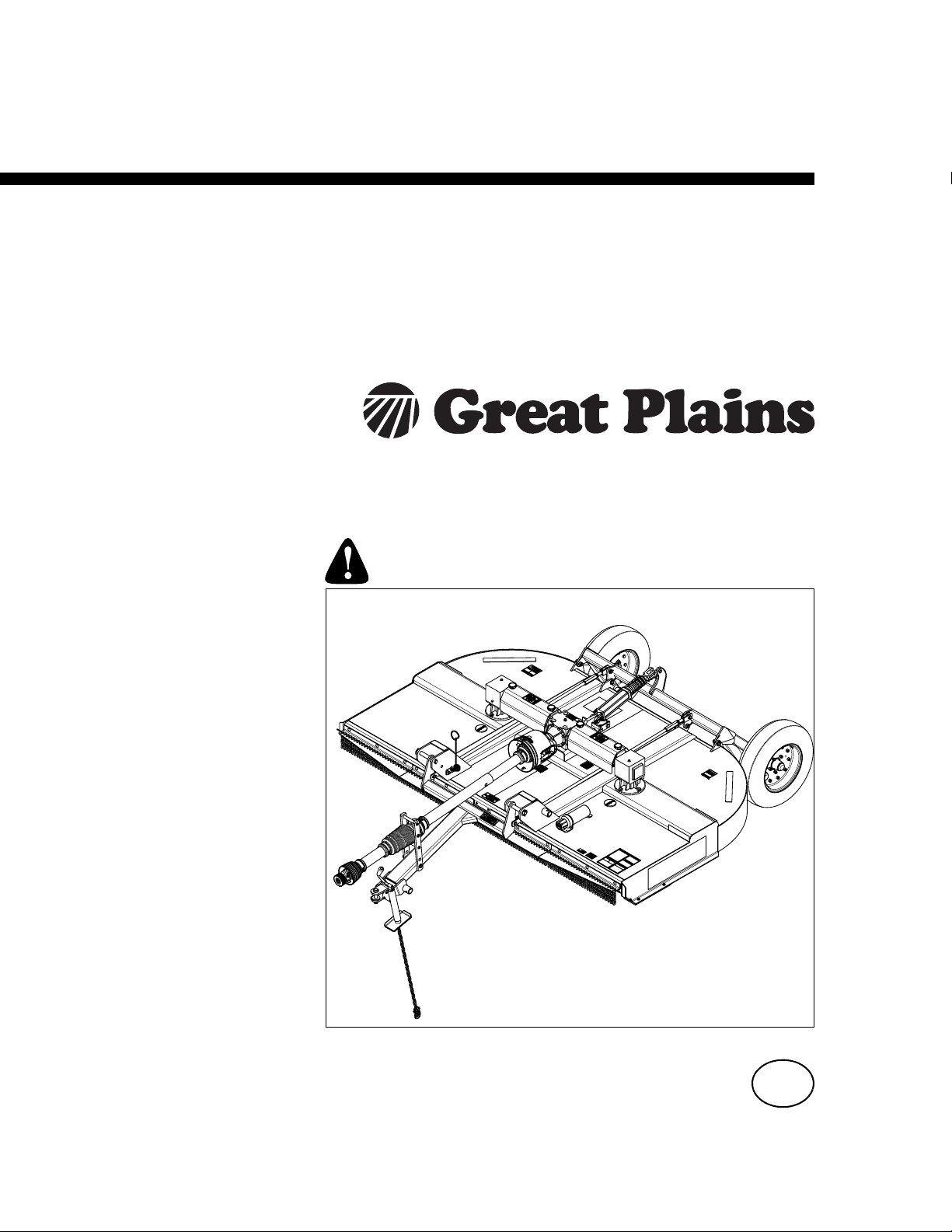
RCR2596 & RCR2510 Rotary Cutters 327-147M 5/26/16
© Copyright 2016 All rights Reserved
Great Plains Manufacturing, Inc. provides this publication “as is” without warranty of any kind, either expressed or implied. While every precaution has been
taken in the preparation of this manual, Great Plains Manufacturing, Inc. assumes no responsibility for errors or omissions. Neither is any liability assumed for
damages resulting from the use of the information contained herein. Great Plains Manufacturing, Inc. reserves the right to revise and improve its products as
it sees fit. This publication describes the state of this product at the time of its publication, and may not reflect the product in the future.
Trademarks of Great Plains Manufacturing, Inc. include: AccuShot, Max-Chisel, Row-Pro,
Singulator Plus, Short Disk, Swath Command, Terra-Tine, Ultra-Chisel, and X-Press.
Registered Trademarks of Great Plains Manufacturing, Inc. include: Air-Pro, Clear-Shot, Discovator, Great Plains, Land Pride, MeterCone,
Nutri-Pro, Seed-Lok, Solid Stand, Terra-Guard, Turbo-Chisel, Turbo-Chopper, Turbo-Max, Turbo-Till, Ultra-Till, Whirlfilter, and Yield-Pro.
Brand and Product Names that appear and are owned by others are trademarks of their respective owners.
Printed in the United States of America
Important Safety Information . . . . . . . . . . . . . 1
Safety at All Times . . . . . . . . . . . . . . . . . . . . . . . . . 1
Look For The Safety Alert Symbol . . . . . . . . . . . . . . 1
Safety Labels . . . . . . . . . . . . . . . . . . . . . . . . . . . . . 4
Introduction . . . . . . . . . . . . . . . . . . . . . . . . . . . 8
Application . . . . . . . . . . . . . . . . . . . . . . . . . . . . . . . 8
Using This Manual . . . . . . . . . . . . . . . . . . . . . . . . . . 8
Owner Assistance . . . . . . . . . . . . . . . . . . . . . . . . . . 8
Serial Number . . . . . . . . . . . . . . . . . . . . . . . . . . . 8
Section 1: Assembly & Set-up . . . . . . . . . . . 10
Tractor Requirements . . . . . . . . . . . . . . . . . . . . . . 10
Weight & Horsepower . . . . . . . . . . . . . . . . . . . . 10
PTO Type & Speed . . . . . . . . . . . . . . . . . . . . . . 10
Pull-Type Hitch . . . . . . . . . . . . . . . . . . . . . . . . . . 10
3-Point Hitch . . . . . . . . . . . . . . . . . . . . . . . . . . . 10
Dealer Preparations . . . . . . . . . . . . . . . . . . . . . . . 10
Torque Requirements . . . . . . . . . . . . . . . . . . . . . . 11
Gearbox Vent Plugs & Dipsticks . . . . . . . . . . . . . . 11
Vent Plug Installation . . . . . . . . . . . . . . . . . . . . . 11
Pull-Type Cutter . . . . . . . . . . . . . . . . . . . . . . . . . . 12
Hitch Assembly . . . . . . . . . . . . . . . . . . . . . . . . . 12
Equal Angle Driveline Installation . . . . . . . . . . . . 13
Constant Velocity Driveline Installation . . . . . . . 14
Pull-Type Tractor Hook-Up . . . . . . . . . . . . . . . . . 15
3-Point Lift-Type Cutter . . . . . . . . . . . . . . . . . . . . . 16
Hitch Assembly . . . . . . . . . . . . . . . . . . . . . . . . . 16
Driveline Installation . . . . . . . . . . . . . . . . . . . . . . . 16
3-Point Tractor Hook-Up . . . . . . . . . . . . . . . . . . 17
Driveline Hook-up to Tractor PTO . . . . . . . . . . . . . 18
Check Driveline Collapsible Length . . . . . . . . . . 18
Shorten Driveline . . . . . . . . . . . . . . . . . . . . . . . . 18
Check Driveline Interference . . . . . . . . . . . . . . . 19
Check Chains . . . . . . . . . . . . . . . . . . . . . . . . . . . . 19
Section 2: Assembly of Optional Equipment 20
Chain Safety Guards (Optional) . . . . . . . . . . . . . . 20
Rubber Safety Guards (Optional) . . . . . . . . . . . . . 21
Section 3: Adjustments . . . . . . . . . . . . . . . . . 22
Pull-Type Leveling & Cutting Height . . . . . . . . . . . 22
Deck Leveling From Front to Back . . . . . . . . . . . 22
Pull-Type Cutting Height . . . . . . . . . . . . . . . . . . 22
3-Point Leveling & Cutting Height . . . . . . . . . . . . . 23
Deck Leveling From Left to Right . . . . . . . . . . . . 23
Deck Leveling From Front to Rear . . . . . . . . . . . 23
Center Link Adjustment . . . . . . . . . . . . . . . . . . . 23
Tailwheel Height Adjustment . . . . . . . . . . . . . . . 24
Section 4: Operating Procedures . . . . . . . . . 25
Operating Checklist . . . . . . . . . . . . . . . . . . . . . . . . 25
Safety Information . . . . . . . . . . . . . . . . . . . . . . . . . 25
Inspection of Tractor & Cutter . . . . . . . . . . . . . . . . 26
Transporting . . . . . . . . . . . . . . . . . . . . . . . . . . . . . 27
Blade Engagement & Disengagement . . . . . . . . . . 27
Blade Engagement . . . . . . . . . . . . . . . . . . . . . . . 27
Blade Disengagement . . . . . . . . . . . . . . . . . . . . 27
Field Operation . . . . . . . . . . . . . . . . . . . . . . . . . . . 28
Turning Angles for Pull-Type Cutters . . . . . . . . . . . 28
Crossing Steep Ditches & Banks . . . . . . . . . . . . . . 29
Unhook 3-Point Cutter . . . . . . . . . . . . . . . . . . . . . . 29
Unhook Pull-Type Cutter . . . . . . . . . . . . . . . . . . . . 29
General Operating Instructions . . . . . . . . . . . . . . . 30
Section 5: Maintenance & Lubrication . . . . . 31
Maintenance . . . . . . . . . . . . . . . . . . . . . . . . . . . . . 31
Tire Maintenance . . . . . . . . . . . . . . . . . . . . . . . . . . 31
Cutter Blade Maintenance . . . . . . . . . . . . . . . . . . . 32
Slip-Clutch Protected Drivelines . . . . . . . . . . . . . . 33
Skid Shoe Maintenance . . . . . . . . . . . . . . . . . . . . . 34
RCR2596 Dual End Flex Couplers . . . . . . . . . . . . 35
RCR2510 Dual End Flex Couplers . . . . . . . . . . . . 35
Tractor Maintenance . . . . . . . . . . . . . . . . . . . . . . . 36
Long Term Storage . . . . . . . . . . . . . . . . . . . . . . . . 36
Ordering Replacement Parts . . . . . . . . . . . . . . . . . 36
Lubrication Points . . . . . . . . . . . . . . . . . . . . . . . . . 37
3-Point Tailwheel Spindle Tube . . . . . . . . . . . . . 37
Tailwheel Hub . . . . . . . . . . . . . . . . . . . . . . . . . . . 37
Pillow Block Bearing (Pull-Type Cutter) . . . . . . . 37
Ratchet Jack . . . . . . . . . . . . . . . . . . . . . . . . . . . . 37
Gearbox . . . . . . . . . . . . . . . . . . . . . . . . . . . . . . . 38
T-Gearbox . . . . . . . . . . . . . . . . . . . . . . . . . . . . . 38
Dual End Flex Coupler . . . . . . . . . . . . . . . . . . . . 38
Driveline U-Joints . . . . . . . . . . . . . . . . . . . . . . . . 39
CV Driveline U-Joints & Profile Shields . . . . . . . 39
Driveline Profiles With Grease Zerk . . . . . . . . . . 39
Driveline Profiles Without Grease Zerk . . . . . . . . 39
Section 6: Specifications & Capacities . . . . . 40
Section 7: Features and Benefits . . . . . . . . . 43
Section 8: Troubleshooting . . . . . . . . . . . . . . 44
Section 9: Torque & Tire Inflation Charts . . . 45
Section 10: Warranty . . . . . . . . . . . . . . . . . . . 47
Table of Contents

1
Important Safety Information
RCR2596 & RCR2510 Rotary Cutters 327-147M
Table of Contents
5/26/16
Important Safety Information
▲
These are common practices that may or may not be applicable to the products described in
this manual.
Safety at All Times
Thoroughly read and understand
the instructions given in this
manual before operation. Refer to
the “Safety Label” section, read all
instructions noted on them.
Do not allow anyone to operate
this equipment who has not fully
read and comprehended this
manual and who has not been
properly trained in the safe
operation of the equipment.
▲The operator must not use drugs
or alcohol as they can change the
alertness or coordination of that
person while operating equipment.
The operator should, if taking over-
the-counter drugs, seek medical
advice on whether he/she can
safely operate the equipment.
▲Operator must start tractor and
operate controls from the driver’s
seat only. Never from the ground.
▲Operator should be familiar with all
functions of the tractor and
attachments, and be able to
handle emergencies quickly.
▲Make sure all guards and shields
are in place and secured before
operating implement.
▲Keep all bystanders away from
equipment and work area.
▲Do not leave tractor or implement
unattended with engine running.
▲Dismounting from a moving tractor
can cause serious injury or death.
▲Do not allow anyone to stand
between tractor and implement
while backing up to implement.
▲Keep hands, feet, and clothing
away from power-driven parts.
▲Watch out for fences, trees, rocks,
wires, etc., while operating and
transporting implement.
▲Turning tractor too tight may cause
hitched machinery to ride up on
wheels. This could result in injury
or equipment damage.
Look For The Safety Alert Symbol
The SAFETY ALERT SYMBOL indicates there is a
potential hazard to personal safety involved and extra
safety precaution must be taken. When you see this
symbol, be alert and carefully read the message that
follows it. In addition to design and configuration of
equipment, hazard control, and accident prevention are
dependent upon the awareness, concern, prudence, and
proper training of personnel involved in the operation,
transport, maintenance, and storage of equipment.
Tractor Shutdown & Storage
▲If engaged, disengage PTO.
▲Lower attached implement to
ground, put tractor in park or set
park brake, turn off engine, and
remove switch key to prevent
unauthorized starting.
▲Wait for all components to come to
a complete stop before leaving the
operator’s seat.
▲Detach and store implement in an
area where children normally do
not play. Secure implement using
blocks and supports.
OFF
REMOVE
Be Aware of
Signal Words
A Signal word designates a degree or
level of hazard seriousness. The
signal words are:
Indicates an imminently hazardous
situation which, if not avoided, will
result in death or serious injury. This
signal word is limited to the most
extreme situations, typically for
machine components that, for
functional purposes, cannot be
guarded.
!
DANGER
Indicates a potentially hazardous
situation which, if not avoided, could
result in death or serious injury, and
includes hazards that are exposed
when guards are removed. It may also
be used to alert against unsafe
practices.
Indicates a potentially hazardous
situation which, if not avoided, may
result in minor or moderate injury. It
may also be used to alert against
unsafe practices.
!
WARNING
!
CAUTION
For Your Protection
▲Thoroughly read and understand
the “Safety Label” section, read
all instructions noted on them.

2
Important Safety Information
RCR2596 & RCR2510 Rotary Cutters 327-147M
Table of Contents
5/26/16
These are common practices that may or may not be applicable to the products described in
this manual.
Use Safety
Lights and Devices
▲Slow moving tractors,
self-propelled equipment, and
towed implements can create a
hazard when driven on public
roads. They are difficult to see,
especially at night.
▲Flashing warning lights and turn
signals are recommended
whenever driving on public roads.
Use A Safety Chain
▲A safety chain will help control
drawn machinery should it
separate from the tractor drawbar.
▲Use a chain with the strength
rating equal to or greater than the
gross weight of the towed
machinery.
▲Attach the chain to the tractor
drawbar support or other specified
anchor location. Allow only
enough slack in the chain to
permit turning.
▲Do not use safety chain for towing.
▲Maximum transport speed for an
attached implement is 20 mph. DO
NOT EXCEED. Never travel at a
speed which does not allow
adequate control of steering and
stopping. Some rough terrains
require a slower speed.
▲As a guideline, use the following
maximum speed weight ratios for
an attached implement:
20 mph when weight of attached
implement is less than or equal to
the weight of machine towing the
implement.
10 mph when weight of attached
implement exceeds weight of
machine towing implement but
not more than double the weight.
▲IMPORTANT: Do not tow a load
that is more than double the weight
of the machine towing the load.
Transport
Machinery Safely
▲Comply with state and local laws.
▲Use towing vehicle and trailer of
adequate size and capacity.
▲Secure equipment towed on a
trailer with tie downs and chains.
▲Sudden braking can cause a trailer
to swerve and upset. Reduce
speed if trailer is not equipped with
brakes.
▲Avoid contact with any over head
utility lines or electrically charged
conductors.
▲Engage park brake when stopped
on an incline.
Practice Safe Maintenance
▲Understand procedure before doing
work. Use proper tools and
equipment, refer to Operator’s
Manual for additional information.
▲Work in a clean dry area.
▲Lower attached implement to the
ground, put tractor in park, turn off
engine, and remove key before
performing maintenance.
▲Allow implement to cool before
working on it.
▲Disconnect battery ground cable (-)
before servicing or adjusting
electrical systems or before welding
on implement.
▲Do not grease or oil implement
while it is in operation.
▲Inspect all parts. Make certain
parts are in good condition &
installed properly.
▲Replace parts on this machine with
genuine Great Plains parts only. Do
not alter this machine in a way
which will adversely affect its
performance.
▲Remove buildup of grease, oil, or
debris.
▲Remove all tools and unused parts
from implement before operation.

3
Important Safety Information
RCR2596 & RCR2510 Rotary Cutters 327-147M
Table of Contents
5/26/16
These are common practices that may or may not be applicable to the products described in
this manual.
Prepare for Emergencies
▲Be prepared if a fire starts.
▲Keep a first aid kit and fire
extinguisher handy.
▲Keep emergency numbers for
doctor, ambulance, hospital, and
fire department near phone.
911
Avoid High
Pressure Fluids Hazard
▲Escaping fluid under pressure can
penetrate the skin causing serious
injury.
▲Avoid the hazard by relieving
pressure before disconnecting
hydraulic lines or performing work
on the system.
▲Make sure all hydraulic fluid
connections are tight and all
hydraulic hoses and lines are in
good condition before applying
pressure to the system.
▲Use a piece of paper or
cardboard, NOT BODY PARTS, to
check for suspected leaks.
▲Wear protective gloves and safety
glasses or goggles when working
with hydraulic systems.
▲DO NOT DELAY. If an accident
occurs, see a doctor familiar with
this type of injury immediately. Any
fluid injected into the skin or eyes
must be treated within
a few hours or
gangrene may
result.
Tire Safety
▲Tire changing can be dangerous
and should be preformed by
trained personnel using the
correct tools and equipment.
▲When inflating tires, use a clip-on
chuck and extension hose long
enough to allow you to stand to
one side and NOT in front of or
over the tire assembly. Use a
safety cage if available.
▲When removing and installing
wheels, use wheel handling
equipment adequate for the
weight involved.
Keep Riders Off
Machinery
▲Never carry riders or use
machinery as a person lift.
▲Riders obstruct operator’s view.
▲Riders could be struck by foreign
objects or thrown from the
machine.
▲Never allow children to operate
equipment.
Wear
Protective Equipment
▲Wear protective clothing and
equipment appropriate for the job
such as safety shoes, safety
glasses, hard hat, and ear plugs.
▲Clothing should fit snug without
fringes and pull strings to avoid
entanglement with moving parts.
▲Prolonged exposure to loud noise
can cause hearing impairment or
hearing loss. Wear suitable
hearing protection such as
earmuffs or earplugs.
▲Operating equipment safely
requires the operator’s full
attention. Avoid wearing radio
headphones while operating
machinery.
Use Seat Belt and ROPS
▲Operate only tractors equipped
with a Roll-Over Protective
Structure (ROPS) and seat belt.
▲Keep folding ROPS in the “locked
up” position at all times.
▲Fasten seat belt snugly and
securely to help protect against
serious injury or death from falling
and machine overturn.
▲Wear protective equipment such
as a hard hat, safety shoes, safety
glasses, and ear plugs.

4
Important Safety Information
RCR2596 & RCR2510 Rotary Cutters 327-147M
Table of Contents
5/26/16
Safety Labels
Your Rotary Cutter comes equipped with all safety labels in
place. They are designed to help you safely operate your
implement. Read and follow their directions.
1. Keep all safety labels clean and legible.
2. Refer to this section for proper label placement. Replace
all damaged or missing labels. Order new labels from your
nearest Great Plains dealer. To find your nearest dealer,
visit our dealer locator at www.greatplainsmfg.com.
3. Some new equipment installed during repair requires
safety labels to be affixed to the replaced component as
specified by Great Plains’. When ordering new
components make sure the correct safety labels are
included in the request.
4. Refer to this section for proper label placement.
To install new labels:
a. Clean surface area where label is to be placed.
b. Spray soapy water onto the cleaned area.
c. Peelbacking fromlabel and press label firmlyonto the
surface.
d. Squeeze out air bubbles with edge of a credit card or
with a similar type of straight edge.
22288
22288
22288
838-614C
2" x 9" Red Reflector
2 places: Rear left side and rear right side of deck
838-615C
2" x 9" Amber Reflector
1 place: Front left side of deck only
818-130C
Caution: Use with 540 RPM PTO only

7
Important Safety Information
RCR2596 & RCR2510 Rotary Cutters 327-147M
Table of Contents
5/26/16
818-540C
Danger: Guard Missing - Do Not
Operate
818-552C
Danger: Rotating Driveline
Hazard - Keep Away
ROTATING DRIVELINE
KEEP AWAY!
838-094C
Warning: High Pressure
22288
22296
22296
33016
818-681C
Notice: 20 MPH Maximum Travel Speed
Located on Pull-Type Hitch and All Gauge Wheels

8
Introduction
RCR2596 & RCR2510 Rotary Cutters 327-147M
Table of Contents
5/26/16
Great Plains welcomes you to the growing family of new
product owners.
This Rotary Cutter has been designed with care and built
by skilled workers using quality materials. Proper
assembly, maintenance, and safe operating practices will
help you get years of satisfactory use from this machine.
Application
The standard utility duty RCR2596 and RCR2510 Series
Rotary Cutters are designed and built by Great Plains to
provide excellent cutting performance on gently sloping
or slightly contoured right-of-ways, pastures, set-aside-
acres, and row crop fields. Their eight and ten foot cutting
widths, 2" to 12" cutting height and ability to cut weeds
and brush up to 1 1/2" diameter make them well suited for
these applications.
The RCR2596 and RCR2510 cutters operate at a PTO
speed of 540 rpm. A category four equal angle driveline
is available on both models and a category four constant
velocity driveline is available on only the RCR2510
model.
Pull-type and three-point type hitches are available. The
RCR2596 is designed for a category I or II three-point
hitch and the RCR2510 is designed for a category II or III
three-point hitch. All three-point hitches are Quick-Hitch
adaptable. The RCR2596 three-point hitch requires a 50-
110 HP tractor and the Pull-type hitch requires a 40-110
HP tractor. The RCR2510 three-point hitch requires a 60-
110 HP tractor and 50-110 HP for Pull-type.
Stump jumpers, main driveline slip-clutches, and
outboard flex couplers are also offered for driveline and
gearbox protection. Safety shields around the cutter are
offered in either chain or rubber.
See “Specifications & Capacities” on page 40 and
“Features & Benefits” on page 43 for additional
information and performance enhancing options.
Using This Manual
•This Operator’s Manual is designed to help familiarize
you with safety, assembly, operation, adjustments,
troubleshooting, and maintenance. Read this manual
and follow the recommendations to help ensure safe
and efficient operation.
•The information contained within this manual was
current at the time of printing. Some parts may change
slightly to assure you of the best performance.
•To order a new Operator’s or Parts Manual, contact
your authorized dealer. Manuals can also be
downloaded, free-of-charge, from our website at
www.greatplainsmfg.com
Terminology
“Right” or “Left” as used in this manual is determined by
facing the direction the machine will operate while in use
unless otherwise stated.
Definitions
Owner Assistance
The Online Warranty Registration should be completed
by the dealer at the time of purchase. This information is
necessary to provide you with quality customer service.
The parts on your Rotary Cutter have been specially
designed by Great Plains and should only be replaced
with genuine Great Plains parts. Contact a Great Plains
dealer if customer service or repair parts are required.
Your Great Plains dealer has trained personnel, repair
parts, and equipment needed to service the implement.
Serial Number
Model No. _____________Serial No. _______________
For quick reference and prompt service, record model
number and serial number in the spaces provided above
and again on warranty page 47. Always provide model
number and serial number when ordering parts and in all
correspondences with your Great Plains dealer. Refer to
Figure 1 for location of your serial number plate.
Serial Number Plate Location
Figure 1
IMPORTANT: A special point of information related
to the following topic. Great Plains’ intention is this
information must be read & noted before continuing.
NOTE: A special point of information that the
operator should be aware of before continuing.
39207
Introduction

9
Introduction
RCR2596 & RCR2510 Rotary Cutters 327-147M
Table of Contents
5/26/16
Further Assistance
Your dealer wants you to be satisfied with your new
Cutter. If for any reason you do not understand any part of
this manual or are not satisfied with the service received,
the following actions are suggested:
1. Discuss the matter with your dealership service
manager making sure that person is aware of any
problems you may have and has had the opportunity
to assist you.
2. If you are still not satisfied, seek out the owner or
general manager of the dealership, explain the
problem, and request assistance.
3. For further assistance write to:
Great Plains
Service Department
P.O. Box 5060
Salina, KS 67402-5060

10
Section 1: Assembly & Set-up
RCR2596 & RCR2510 Rotary Cutters 327-147M
Table of Contents
5/26/16
Tractor Requirements
Weight & Horsepower
Tractor horsepower and weight must be capable of
controlling the cutter under all operating conditions.
Tractors outside the horsepower range must not be used.
RCR2596 cutters
Three-point . . . . . . . . . . . . . . . . . . . . . . . 50-110 HP
Pull-type . . . . . . . . . . . . . . . . . . . . . . . . . 40-110 HP
R1CR2510 cutters
Three-point . . . . . . . . . . . . . . . . . . . . . . . 60-110 HP
Pull-type . . . . . . . . . . . . . . . . . . . . . . . . . 50-110 HP
!WARNING
Ballast weights may need to be added to your tractor to
maintain steering control. Refer to your tractor operator’s
manual to determine proper ballast requirements.
Tractor Requirement
Horsepower. . . . . . . . . . . . . . . . . . . . . . . . . . 55 HP
PTO Type & Speed
Tractor’s rear power take-off (PTO) speed and spline type
must be capable of matching the cutter’s PTO type and
speed.
RCR2596 and RCR2510 cutters
540 RPM 1 3/8"-6 spline rear power take-off
Pull-Type Hitch
Refer to Figure 1-1:
Distances between center of drawbar hitch pin hole to
end of tractor PTO shaft (“A” dimension) and from top of
drawbar hitch to center of PTO shaft (“B” dimension)
must be maintained when using the Pull-type hitches.
•“A” = 14"
•“B” = 8"
PTO to Drawbar Distances
Figure 1-1
IMPORTANT: PTO damage may occur if distances
“A” and “B” are not properly maintained.
22273
3-Point Hitch
The lower 3-point arms of the 3-point hitch must be
stabilized to prevent side-to-side movement. Most
tractors have sway blocks or adjustable chains for this
purpose. Category of hitch is dependent upon the series
of cutter being used.
•RCR2596 (Category l or ll hitch)
•RCR2510 (Category ll or lll hitch)
Dealer Preparations
Read and understand the operator’s manual for your
cutter. An understanding of how it works will aid in the
assembly and setup of your cutter.
This Rotary Cutter has been partially assembled at the
factory. However, some assembly will be necessary to
attach the hitch, driveline, and guards to the cutter.
It is best to go through the Assembly Checklist before
assembling the cutter. Speed up your assembly task and
make the job safer by having all the needed parts and
equipment readily at hand.
Assembly Checklist
Check Reference
Fasteners and pins that were shipped
with the cutter. NOTE: All hardware from
the factory has been installed in the
location where it will be used. If a part or
fastener is temporarily removed for
assembly reasons, remember where it
goes.Keep the parts separated.
Operator’s
Manual
Be sure the parts get used in the correct
location. By double checking while you
assemble, you will lessen the chance of
using a bolt incorrectly that may be
needed later.
Operator’s
Manual
All grease fittings are in place and
lubricated.
Section 5
Page 32
Safety labels are correctly located and
legible. Replace if damaged.
Safety
Information
Page 1
Inflate tires to specified PSI air pressure.
Tighten wheel bolts to specified torque.
Section 8
Page 40
Red and amber reflectors are correctly
located and visible when the cutter is in
the transport position.
Safety
Information
Page 1
Have a minimum of 2 people at hand
while assembling the cutter.
Operator’s
Manual
Have a fork lift or loader along with
chains and safety stands that are sized
for the job ready for the assembly task.
Operator’s
Manual
Section 1: Assembly & Set-up

11
Section 1: Assembly & Set-up
RCR2596 & RCR2510 Rotary Cutters 327-147M
Table of Contents
5/26/16
Torque Requirements
Refer to “Torque Values Chart” on page 45 to
determine correct torque values for common bolts. See
“Additional Torque Values” at bottom of chart for
exceptions to standard torque values.
Gearbox Vent Plugs & Dipsticks
Vent Plug Installation
Refer to Figure 1-2 & Figure 1-3:
Vent plugs are shipped loose and packaged with the
Operator’s Manual. Remove temporary solid plugs on top
of gearboxes and replace with included 3/8" vent plug.
See your nearest Great Plains dealer if vent plugs are
missing.
T-Gearbox
Figure 1-2
Blade Drive Gearboxes
Figure 1-3
IMPORTANT: Rotary Cutters are shipped with a
solid plug in the gearbox to prevent loss of oil during
shipping and handling. The solid plug on top of the
gearbox must be replaced with a vented dipstick. Do
not operate cutter without vented dipstick installed.
22320
Remove 3/8" T-Box Solid
Plug & Install Vent Plug
DO NOT
OVERFILL!
30216
DO NOT
OVERFILL!
Oil Level
Plug
Remove 3/8" Solid Plug &
Install Vent Plug

12
Section 1: Assembly & Set-up
RCR2596 & RCR2510 Rotary Cutters 327-147M
Table of Contents
5/26/16
Pull-Type Cutter
Hitch Assembly
Refer to Figure 1-4 for RCR2596 hitch assembly and
Figure 1-5 for RCR2510 hitch assembly:
1. Assemble tongue (#1) to the deck using hitch
pins (#2), spacer tubes (#3) and linchpins (#4).
NOTE: Do not tighten hardware to the correct
torque until assembly is complete.
NOTE: If preferred, the front guards may be
assembled first. See “Assembly of Optional
Equipment” on page 20 for front guard assembly
instructions.
2. Attach level rod assemblies (#8) to tongue (#1) using
clevis pins (#5), flat washers (#6) and cotter
pins (#7). Make sure level rod adjusting nuts are
threaded the same distance on both rods. This will
ensure a level unit.
3. Remove hydraulic hose holder (#9) from the hitch
and install to the cutter deck with 3/4" x 1 1/2" GR5
hex head cap screw (#12) and 3/4" hex locknut (#13)
as shown. Tighten mounting bracket hardware as
needed to secure hose holder in place.
4. Route hydraulic hose through the hose holder loop.
5. Remove parking jack (#10) from its storage position
on the deck and attach to the tongue (#1). Secure
with attached pin (#11). Adjust jack to desired height.
RCR2596 Hitch Assembly
Figure 1-4
22302
RCR2510 Hitch Assembly
Figure 1-5
22290

13
Section 1: Assembly & Set-up
RCR2596 & RCR2510 Rotary Cutters 327-147M
Table of Contents
5/26/16
4. Slide slip-clutch end of driveline onto gearbox input
shaft until hole in yoke aligns with notch in shaft.
5. Insert 2- bolts (#10) through holes in driveline yoke
as shown and secure with lock washers (#9) and
nuts (#10). Tighten bolts to 45-50 ft-lbs of torque.
6. Push/pull on driveline yoke to be sure it is securely
fastened to the gearbox shaft.
7. Insert jackshaft of driveline (#2) through bearing
support assembly (#3). Pull bearing support
assembly fully against driveline (#2) to extend
jackshaft splines fully through the bearing.
8. Attach main driveline (#4) to jackshaft of
driveline (#2) by pulling on locking collar and pushing
driveline yoke forward onto the jackshaft until locking
collar has locked in place. Push/pull on driveline yoke
to be sure it is securely fastened to jackshaft (#2).
9. Tighten set screw in bearing locking collar (#3).
10. Rotate gearbox shield access doors (#7) closed and
snap in place.
NOTE: Make sure locking collar on bearing (#3) is
facing rearward toward the cutter gearbox.
RCR2596 & RCR2510
Equal Angle Driveline Assembly
Figure 1-6
22303
Equal Angle Driveline Installation
Refer to Figure 1-6:
Equal angle drivelines can be installed on RCR2596 and
RCR2510. Maximum turning angle is limited to 35
degrees.
!WARNING
Make certain all driveline yokes are securely fastened at both
ends. A loose yoke can work free allowing the driveline to
rotate uncontrollably causing machine damage and bodily
injury or death to anyone nearby.
1. Unsnap one end of gearbox shield access doors (#7)
and rotate doors open.
2. Remove protective sleeve (#11) from input shaft of
gearbox (#1) and discard.
3. Remove nuts (#10), lock washers (#9), and clamp
bolts (#8) from slip-clutch end of driveline (#2).
IMPORTANT: Maximum equal angle driveline
turning angle is limited to 35 degrees.
IMPORTANT: The drivelines must be lubricated
before putting them into service. Refer to
“Lubrication Points” on page 37.

14
Section 1: Assembly & Set-up
RCR2596 & RCR2510 Rotary Cutters 327-147M
Table of Contents
5/26/16
RCR2510 Constant Velocity Driveline Assembly
Figure 1-7
22304
Constant Velocity Driveline Installation
!WARNING
Make certain all driveline yokes are securely fastened at both
ends. A loose yoke can work free allowing the driveline to
rotate uncontrollably causing machine damage and bodily
injury or death to anyone nearby.
Refer to Figure 1-7:
Constant velocity driveline can be installed on the
RCR2510 cutter only. Maximum turning angle is limited to
80 degrees.
1. Unsnap one end of gearbox shield access doors (#7)
and rotate doors open.
2. Remove protective sleeve (#11) from input shaft of
gearbox (#1) and discard.
3. RCR2510 only: Remove 2-nuts (#10), 2-lock
washers (#9), and 2-bolts (#8) from slip-clutch end of
driveline (#2). Slide slip-clutch end of driveline onto
input shaft of gearbox (#6) until hole in yoke aligns
with notch in input shaft.
4. RCR2510 only: Insert 2-bolts (#10) through holes in
driveline yoke as shown and secure with lock
washers (#9) and nuts (#10).
5. Tighten nut (#10) to 45-50 ft-lbs of torque.
6. Push/pull on driveline yoke to be sure it is securely
fastened to the gearbox shaft.
7. Rotate gearbox shield access doors (#7) closed and
snap in place.
IMPORTANT: Maximum constant velocity driveline
turning angle is limited to 80 degrees.
IMPORTANT: The drivelines must be lubricated
before putting them into service. Refer to
“Lubrication Points” on page 37.
NOTE: Do not tighten hardware until assembly or
driveline is complete.
8. Fully insert jackshaft driveline (#1) into pillow block
bearing (#7).
9. Secure bearing support (#2) with 1/2"-13 x 3 1/2"
bolts (#3) and hex flange nuts (#4). Do not tighten
nuts (#4) at this time.
10. Remove lock nut (#12) and bolt (#13) from bolted
coupler end of driveline (#5).
11. Push bolted coupler end of main driveline (#5) onto
the jackshaft of driveline (#1) as far as possible.
12. Attach driveline (#5) to jackshaft driveline with
removed bolt (#13) and lock nut (#12). Tighten lock
nut to 45-50 ft-lbs of torque.
13. Tighten nuts (#4) to the proper torque.
14. Rotate locking collar in bearing (#7) clockwise until
tight.
15. Tighten set screw in bearing (#7) locking collar.
NOTE: Make sure locking collar on bearing (#7) is
facing forward toward the tractor.

15
Section 1: Assembly & Set-up
RCR2596 & RCR2510 Rotary Cutters 327-147M
Table of Contents
5/26/16
Pull-Type Tractor Hook-Up
Refer to Figure 1-8:
!DANGER
A Crushing Hazard exists when hooking-up equipment to a
tractor. Do not allow anyone to stand between tractor and
implement while backing-up to implement. Do not operate
hydraulic 3-point lift controls while someone is directly
behind tractor or near implement.
!WARNING
Always disengage PTO, put tractor in park or set park brake,
shut tractor engine off, remove ignition key, and wait for
blades to come to a complete stop before dismounting tractor.
Distances between center of drawbar hitch pin hole to
end of tractor PTO shaft and from top of drawbar hitch to
center of PTO shaft must be maintained when using
Pull-type hitches. See “Pull-Type Hitch” on page 10 for
correct distances.
1. Make certain jack stand (#1) is properly attached to
cutter hitch and secured with attachment pin (#2).
2. Back tractor within close proximity of cutter
clevis (#6).
3. Raise or lower jack (#1) to align clevis (#6) with
tractor drawbar. Drawbar should fit between lower
and upper plates of clevis.
4. Back tractor up to cutter hitch until holes in the
drawbar and clevis (#6) are aligned.
IMPORTANT: Jack attachment pin must be fully
inserted and secured before working on or around a
cutter not hooked to the tractor drawbar.
5. Insert 1" flat washers (#5) above and below tractor
drawbar.
6. Insert 1" -8 x 4 1/2" GR5 hex bolt (3) through top of
clevis (#6), 1" washer (#5), tractor drawbar,
remaining 1" washer (#5), and through bottom plate
in clevis (#6). Secure bolt with locknut (#4). Tighten
locknut snugly to remove all play and then back nut
one-quarter turn.
7. Attach pull collar end of driveline (#8) to tractor PTO
shaft. Secure with locking device. Pull on both ends
of the driveline to make sure it is secured to the
tractor and gearbox shafts.
8. Thread hydraulic hose (#9) through spring hose
loop (#10 ) and attach to tractor hydraulic outlet.
9. Lower park jack (#1)until cutter hitch weight is
supported by tractor drawbar, remove detent pin
(#2), and park jack (#1).
10. Store park jack (#1) on the cutter deck with detent pin
as shown.
Safety Chain
Refer to Figure 1-8:
When towing implements on the road, use safety
chain (#7) to contain the implement should the hitch pin
become lost. After attaching the safety chain to the
tractor, check chain length by driving the tractor to the
right and to the left for a short distance. If necessary,
re-adjust chain length to eliminate a tight or loose chain.
Make sure the chain hook is securely locked in place
when finished.
NOTE: Length of leveling rod couplers may need
adjusting to obtain correct drawbar height. See
“Pull-Type Leveling & Cutting Height” on page 22
Pull-Type Tractor Hook-Up
Figure 1-8
22310
RCR2510 jack storage location shown with
arrow. Jack storage location is on the deck top
for RCR2596 cutters.

16
Section 1: Assembly & Set-up
RCR2596 & RCR2510 Rotary Cutters 327-147M
Table of Contents
5/26/16
3-Point Lift-Type Cutter
Hitch Assembly
Refer to Figure 1-9:
1. Insert 5/8" long bushings (#22) into the bottom holes
of A-Frame hitch plates (#2) and attach hitch plates to
the lower bolt holes of the 3-point hitch plates with
3/4"-10 x 2" GR5 bolts (#10), flat washers (#17), and
lock nuts (#14).
2. Place 2" long bushing (#6) between the two
A-Frame hitch plates and insert 1"-8 x 4 1/2" GR5
cap screw (#11) through the A-Frame hitch plate
holes and bushing. Secure bolt with lock nut (#15).
3. Attach the two short braces (#7) on rear brace
assembly (#1) between the back two holes in the
A-Frame hitch with clevis pin (#20). Secure clevis pin
with flat washer (#18) and cotter pin (#19).
4. Attach the two longer braces (#4) on rear brace
assembly (#1) to the front hole of the lug welded
behind the gearbox mount with 1"-8 x 3" GR5 cap
screw (#12) and lock nut (#15).
5. Assemble rear braces (#5) to the inside of inner rear
lugs with 3/4"-10 x 1 3/4 GR5 cap screws (#13) and
lock nuts (#14).
NOTE: Do not tighten hardware until assembly of
hitch and driveline is complete. Refer to “Torque
Values Chart” on page 45.
6. Install remaining clevis pin (#20), flat washer (#18),
and cotter pin (#19) in the top front holes in the
A-Frame hitch as shown.
7. Attach driveline hook (#8) to A-frame (#3) using
5/16"-18 x 1 1/4" bolt (#9) and lock nut (#16).
8. Tighten all assembled hardware to the correct torque.
Driveline Installation
Refer to Figure 1-9:
1. Unsnap one end of gearbox shield access doors and
rotate doors open.
2. Remove protective sleeve from gearbox input shaft.
3. Remove nut (#26), lock washer (#25), and clamp
bolt (#24) from slip-clutch end of driveline.
4. Slide slip-clutch end of driveline onto gearbox input
shaft until hole in yoke aligns with notch in shaft.
5. Insert clamp bolt (#24) through hole in yoke and
secure with lock washer (#25) and nut (#26). Tighten
nut to the correct torque.
6. Push/pull on driveline yoke to be sure it is securely
fastened to the gearbox shaft.
7. Rotate gearbox shield access doors closed and snap
in place.
8. Collapse driveline (#21) by pushing on tractor end of
driveline toward the gearbox.
9. Support driveline on driveline support hook (#8).
Lift Type Cutter 3-Point Assembly
Figure 1-9
22289

17
Section 1: Assembly & Set-up
RCR2596 & RCR2510 Rotary Cutters 327-147M
Table of Contents
5/26/16
a Category 1 tractor will be positioned outside the
lower hitch holes “B” on RCR2596 cutters.
5. Attach cutter to lower 3-point lift arms as follows:
RCR2596 With Cat. I Tractor Hitch
a. Discard bushings (#3 & #4).
b. Insert hitch pins (#2A) through hitch hole “A” first
and then hitch hole “B”.
c. Slide lower 3-point lift arm hitch holes over end of
hitch pins (#2A).
RCR2596 With Cat. II Tractor Hitch
a. Discard bushings (#3 & #4).
b. Insert hitch pins (#2A) through hitch hole “A”, lower
3-point arm hitch holes, and then hitch hole “B”.
RCR2510 With Cat. II Tractor Hitch
a. Discard bushing (#3).
b. Insert hitch pins (#2B) through hitch hole “B”, lower
3-point arm hitch holes, bushing (#4), and then
hitch hole “A”.
RCR2510 With Cat. III Tractor Hitch
a. Place bushing (#3) inside lower 3-point lift arm
hitch holes.
b. Insert hitch pins (#2B) through lower hitch
hole “B”, bushing (#3), bushing (#4), and then
through hitch hole “A”.
6. Secure hitch pins (#2A or #2B) with linchpins (#1).
7. Connect top center 3-point link to the upper pivot
hitch using 1" clevis pin (#6), flat washer (#7), and
cotter pin (#5). Bend on or both legs of cotter pin to
prevent it from falling out.
8. The center 3-point link should be adjusted to allow for
lateral float. Please consult you tractor’s manual for
adjusting instructions.
3-Point Lift Type Cutter Tractor Hook-Up
Figure 1-10
22293
37298
3-Point Tractor Hook-Up
Refer to Figure 1-10:
!DANGER
A Crushing Hazard exists when hooking-up equipment to a
tractor. Do not allow anyone to stand between tractor and
implement while backing-up to implement. Do not operate
hydraulic 3-point lift controls while someone is directly
behind tractor or near implement.
!WARNING
Always disengage PTO, put tractor in park or set park brake,
shut tractor engine off, remove ignition key, and wait for
blades to come to a complete stop before dismounting tractor.
1. Locate cutter on a flat level surface.
2. Determine the hitch category of the tractor that will
be used:
a. Category I tractors will have a lower 3-point hitch
hole diameter of 7/8". The top link hole diameter
(cutter end) will be 3/4".
b. Category II tractors will have a lower 3-point hitch
hole diameter of 1 1/8". The top link hole diameter
(cutter end) will be 1".
c. Category III tractors will have a lower 3-point
hitch hole diameter of 1 7/16". The top link hole
diameter (cutter end) will be 1 5/16".
3. Remove lower linchpins (#1) and hitch pins (#2) from
lower clevises. Remove upper cotter pin (#5), flat
washer (#7), and hitch pin (#6) from upper clevis.
4. Slowly back the tractor up to the cutter while using
the tractor’s 3-point hydraulic control lever to align
lower 3-point arm hitch holes with hitch pin holes in
the cutter’s lower clevis The lower 3-point lift arms of

18
Section 1: Assembly & Set-up
RCR2596 & RCR2510 Rotary Cutters 327-147M
Table of Contents
5/26/16
Driveline Hook-up to Tractor PTO
!DANGER
Do not engage tractor PTO while hooking-up and unhooking
driveline or while someone is standing near the driveline. A
person’s body and/or clothing can become entangled in the
driveline resulting in serious injury or death.
!DANGER
All guards and shields must be installed and in good working
condition at all times during cutter operation.
!WARNING
Always disengage PTO, put tractor in park or set park brake,
shut tractor engine off, remove ignition key, and wait for
blades to come to a complete stop before dismounting tractor.
!WARNING
Do not over-speed PTO or machine breakage may result.
Some tractors are equipped with multispeed PTO ranges. Be
certain your tractor’s PTO is set for the cutter’s rated PTO
speed. See Specifications & Capacities for rated PTO speed.
!WARNING
Do not use a PTO adapter. A PTO adapter will increase strain
on the tractor’s PTO shaft resulting in possible damage to
shaft and driveline. It will also defeat the purpose of the
tractor’s master shield and could cause bodily injury or death.
1. Park tractor on a level surface. Slowly engage tractor
3-point lift lever to raise cutter until gearbox shaft is in
line (level) with tractor PTO shaft.
2. Support cutter deck at this height with support jacks
or blocks to keep cutter from drifting down.
3. Place gear selector in park, set park brake, shut
tractor off, and remove switch key.
Refer to “Figure 1-10” on page 17:
4. Pull back on driveline yoke collar (#12) and push
driveline yoke onto the tractor PTO shaft. Release
pull collar and continue to push driveline yoke
forward until pull collar locks in place.
5. Move driveline yoke back and forth several times to
make sure yoke is locked in place.
IMPORTANT: An additional driveline may be
required if cutter is to be used on more than one
tractor, especially if a Quick Hitch is used.
The driveline must be lubricated before putting it into
service. Refer to “Lubrication Points” on page 37.
The tractor’s PTO shaft and cutter gearbox shaft
must be aligned and level with each other when
hooking-up the driveline to the tractor.
6. If driveline yoke locks in place, skip to “Check
Driveline Interference” on page 19.
7. Continue with “Check Driveline Collapsible
Length” below.
Check Driveline Collapsible Length
1. Make sure driveline is properly installed and level
before checking driveline collapsible length. (Refer to
“Driveline Hook-up to Tractor PTO” instructions on
page 18.)
Refer to Figure 1-11 on page 19:
2. With driveline level, measure (“B” dimension) back
from universal joint shield to end of outer driveline
shield as shown in Figure 1-12.
3. If measurement is 1" or more, skip to “Check
Driveline Interference” on page 19. If measurement
is less than 1", shorten driveline using instructions
provided below.
Shorten Driveline
Refer to Figure 1-11 on page 19:
Be sure to first check driveline collapsible length above. If
required, shorten driveline as follows:
1. Unhook driveline from tractor PTO shaft and pull
outer and inner drivelines apart.
2. Reattach outer driveline to tractor PTO shaft. Pull on
inner and outer drivelines to be sure universal joints
are properly secured.
3. Hold inner and outer drivelines parallel to each other:
a. Measure 1" (“B” dimension) back from outer
driveline universal joint shield and make a mark at
this location on the inner driveline shield.
b. Measure 1" (“B” dimension) back from the inner
driveline universal joint shield and make a mark at
this location on the outer driveline shield.
4. Remove driveline from tractor and gearbox shafts.
5. Measure from end of inner shield to scribed mark
(“X” dimension). Cut off inner shield at the mark. Cut
same amount off the inner shaft (“X1” dimension).
6. Measure from end of outer shield to scribed mark
(“Y” dimension). Cut off outer shield at the mark. Cut
same amount off the outer shaft (“Y1” dimension).
7. Remove all burrs and cuttings.
8. Apply multi-purpose grease to the inside of the outer
shaft and reassemble driveline.
IMPORTANT: A driveline that is too long can bottom
out causing structural damage to tractor and cutter.
Always check driveline collapsed length during initial
setup, when connecting to a different tractor, and
when alternating between using a quick hitch and a
standard 3-point hitch. More than one driveline may
be required to fit all applications.
This manual suits for next models
1
Table of contents
Other GREAT PLAINS Cutter manuals