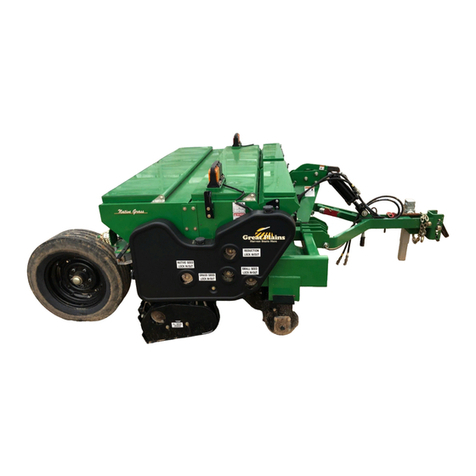
GREAT PLAINS Turbo Max 2400TM User manual

Operator Manual
Turbo Seeder
Turbo Max 2400TM - 4000TM
Terra Max HT1100-20 - HT1100-40
Read the Operator's manual entirely. When you see this symbol, the subsequent
instructions and warnings are serious - follow without exception.Your life and the
lives of others depend on it!
Cover illustration may show optional equipment not supplied with standard unit.
© Copyright 2021 892-120M

This Page Intentionally Left Blank

Page 3
OPERATION MANUAL
Table of Contents
TABLE OF CONTENTS
INTRODUCTION
.........................................................................................................................
5
LIMITED WARRANTY
................................................................................................................
6
Orbit-Air / Zero-Max Identification ..........................................................................................7
Safety Information ..................................................................................................................8
SAFETY Decals................................................................................................................9
Operator’s Manual Review...............................................................................................9
Operator Safety..............................................................................................................10
Safety Guidelines............................................................................................................10
Granular Chemical
Safety...............................................................................................
11
Hydraulic
Safety..............................................................................................................
11
Transport Safety
.............................................................................................................
11
Storage
Safety
................................................................................................................12
Orbit-Air Applicator ...............................................................................................................12
SET UP / OPERATION
.............................................................................................................
15
Control Unit Wiring Connections ..........................................................................................15
Hydraulics ............................................................................................................................17
Safe Operation .....................................................................................................................18
Control Unit ..........................................................................................................................19
Air Pressure Gauge..............................................................................................................20
Closure Slides ......................................................................................................................21
Calibration ............................................................................................................................22

Page 4
OPERATION MANUAL
Table of Contents
Table of Contents
(Continued)
MAINTENANCE
........................................................................................................................
24
Routine Maintenance / Inspection .......................................................................................24
Hydraulic Blower.............................................................................................................24
Bearings..........................................................................................................................25
Lubrication......................................................................................................................26
Safety..............................................................................................................................27
Clutches………………………………………………………………....................................27
Metering Wheels….………..............................................................................................29
Deflector Packages………..............................................................................................30
Post-Season Maintenance ...................................................................................................31
Pre-Season Maintenance.....................................................................................................32
Troubleshooting ...................................................................................................................33
INDEX
........................................................................................................................................
36

Page 5
OPERATION MANUAL
Introduction
INTRODUCTION
this applicator is designed to provide you with years of accurate and dependable
performance when used for the purpose for which it was intended.
To make sure your applicator provides you with safe, efficient, and trouble-free operation, all
personnel that operate this applicator must read and understand all the information included in
this operator’s manual. It is the responsibility of the owner(s) of this equipment to ensure that
the operator is fully instructed and understands the contents of this manual. If you have any
questions about this manual or the equipment, contact your Gandy dealer, or the factory.
ALWAYS use original Gandy service parts as substitute parts could adversely affect equipment
performance and warranty.
DEALER
Your authorized dealer is your primary source for parts and service. If you need assistance
with the operation or maintenance of this applicator, contact your dealer, or the factory. For
future reference, write the dealer’s name and phone number below:
Purchase Date:
Dealership:
Salesperson:
Address:
City/State/Zip:
Phone:
Email:
Web:
Further Assistance
For additional help with understanding these assembly instructions or for any other assembly or
setup related questions, please contact our service department at the following address:
Great Plains Service Department
1525 E. North St.
P.O. Box 5060
Salina, KS 67402-5060
Or call us at (800) 270-9302 to speak over the phone with a service representative.
Copies of this machine’s operator manual are available by mail or online. Please visit
www.greatplainsag.com and follow the product link for information on your machine.

Page 6
OPERATION MANUAL
Introduction
Great Plains (a division of Great Plains Manufacturing, Inc.) warrants to the original
purchaser that this Great Plains machine will be free from defects in material and work-
manship for a period of one year (Parts & Labor) from the rst use date when used as
intended for personal use; ninety days for custom/commercial or rental use.
Second year limited warranty covers Parts ONLY (personal usage only, excluding labor
and wear items). is warranty is limited to the replacement of any defective part by Great
Plains. Great Plains reserves the right to inspect any equipment or part which are claimed
to have been defective in material or workmanship.
e following items and/or conditions are NOT COVERED UNDER WARRANTY: Fail-
ures resulting from the abuse or misuse of the equipment, failures occurring as a result of
accidental damage or Force Majeure, failures resulting from alterations or modications,
failures caused by lack of normal maintenance as outlined in the operator’s manual, re-
pairs made by non-authorized personnel, items replaced or repaired due to normal wear
(such as wear items and ground-engaging components including, but not limited to, disc
blades, chisel points, tires, bushings, and scrapers), repeat repair due to improper diagno-
sis or improper repair by the dealer, temporary repairs, service calls and/or mileage to and
from customer location, overtime premium, or unit hauling expenses. e warranty may
be voided if the unit is towed at speeds in excess of 20 miles per hour (32 kilometers per
hour), or failures occurring from soils with rocks, stumps, or other obstructions.
Great Plains reserves the right to make changes in materials or design of the product at
any time without notice. e warranty shall not be interpreted to render Great Plains
liable for damages of any kind, direct or consequential or contingent to property. Fur-
thermore, Great Plains shall not be liable for damages resulting from any cause beyond its
control. is warranty does not extend to crop loss, losses caused by planting or harvest
delays or any expense or loss of labor, supplies, rental machinery, or for any other reason.
No other warranty of any kind whatsoever expressed or implied, is made with respect
to this sale; and all implied warranties of merchantability and tness for a particular
purpose which exceed the obligations set forth in this written warranty are hereby
disclaimed and excluded from this sale.
his warranty is not valid unless registered by a certied Great Plains dealer.

Page 7
OPERATION MANUAL
Introduction
ORBIT-AIR / ZERO-MAX IDENTIFICATION
Orbit-Air Serial Number / Model Number
The Company places a serial / model number nameplate on the
front of the Turbo-Seeder (above Zero-Max) for easy identification.
For parts, service, or technical information, always provide your
dealer with the model and serial number.
Model:
Serial No.:
Zero-Max Serial Number / Model Number
The Company places a serial number / model number
nameplate on the side of the Zero-Max rate controller for easy
identification.
Model:
Serial No.:

Page 8
OPERATION MANUAL
Introduction
SAFETY INFORMATION
This Operator’s Manual provides important safety messages that are posted on Orbit-Air
applicators. ALWAYS read and obey all safety messages.
Safety Alert
Symbol
Not all decals on the Orbit-Air Applicator have the safety alert symbol. This symbol alerts
you to hazards that have the potential to kill or hurt you and/or others, or cause damage to
equipment or property. Safety messages will be preceded by the safety alert symbol and the
word WARNING, CAUTION, or IMPORTANT.
These words mean:
W
ARNING
Hazards or unsafe practices that COULD result in severe personal injury or death.
CAUTION
Hazards or unsafe practices that COULD result in personal injury, product damage, or
property damage.
IMPORT
ANT
Provides practical information and potential consequences.
NOTE
Provides additional information about a component or process.
Notes will call attention to issues to be kept in mind regarding the applicable situation.

Page 9
OPERATION MANUAL
Introduction
SAFETY DECALS
Keep safety decals clean and legible at all times. Replace decals that are missing or have
become illegible. Safety decals are available from the factory.
Safety Decal Installation
• Be sure the installation area is clean and dry.
• Decide on the exact position before removing the backing paper.
• Remove the smallest portion of the backing paper.
• Align the decal over the desired area and press the small portion of the decal into place.
• Remove the remainder of the backing paper and press the entire decal in place.
• Pierce any air pockets and smooth them out.
Familiarize yourself with the location and message of all safety decals.
OPERATOR’S MANUAL REVIEW
ALL OPERATORS must read and understand the Operator’s Manual before working with
the applicator. Review the Operator’s Manual and safety decals of this machine before each
season of use. The Safety Alert Symbol is on all pertinent safety decals. When you see the
symbol, follow the instructions to avoid injury or death.

Page 10
OPERATION MANUAL
Introduction
Figure 1. Safety Decal
Locations
OPERATOR SAFETY
Applicator owners must give operation instructions to employees or operators before
allowing them to operate the applicator, and at least annually thereafter, according to OSHA
(Occupational Safety and Health Administration) Regulation 1928.57.
SAFETY GUIDELINES
1. Store a first aid kit in a visible, accessible location, and know how to use it.
2. Keep safety decals clean and legible at all times. Replace missing or damaged decals.
3. Before servicing, adjusting, repairing, or unplugging the applicator, stop the machine, set
the parking brake, and wait for all moving parts to come to a complete stop.

Page 11
OPERATION MANUAL
Introduction
4. Ensure that all guards and shields are in place. Replace any that are damaged.
5. Do not allow riders on the applicator.
GRANULAR CHEMICAL SAFETY
1. Read and strictly follow the manufacturer’s instructions found on the product container.
2. Wear chemically resistant clothing, gloves, and safety goggles.
3. Avoid contact with skin and eyes.
4. Wear a respirator as directed by the chemical manufacturer.
5. Wash thoroughly after working with chemicals, especially before eating.
6. Wash all clothing contaminated by chemicals.
7. Wash down the applicator prior to any maintenance. Dispose of wash water in accordance
with local standards and laws.
8. Know the poison control emergency telephone numbers in your area.
HYDRAULIC SAFETY
1. Keep hydraulic components clean so that leaks can be easily identified.
2. Replace damaged hoses and fittings.
3. Use a piece of cardboard when trying to pinpoint leaks. Wear heavy gloves and a face
shield.
4. Have hydraulic components repaired by a qualified repair facility. Makeshift repairs may
fail suddenly creating a hazardous condition.
5. If injured by a high pressure stream of hydraulic fluid, seek medical attention immediately.
Serious infection can result.
TRANSPORT SAFETY
1. Be sure that a Slow Moving Vehicle (SMV) sign and all reflectors and lights required by
local authorities are clean, functional, and in their proper place.
2. Do not exceed the maximum speed rating for the machine being operated.
3. Ensure that the booms and implement wings are folded and latched in place.
4. Disengage the metering drive. Failure to do so may result in the metering of seed or
chemicals onto roadways.

Page 12
OPERATION MANUAL
Introduction
STORAGE SAFETY
1. Store the applicator on a firm, level surface.
2. Thoroughly clean the applicator before storing to avoid contaminating the surrounding
area with chemical or seed residue. Dispose of the wash water in accordance with local
standards and laws.
ORBIT-AIR APPLICATOR
The Orbit-Air applicator is designed to efficiently broadcast seeds and granular chemicals. This
machine operates by using a hydraulically powered fan to blow product through an air delivery
system.
Figure 2. Orbit-Air
Applicator

Page 13
OPERATION MANUAL
Introduction
1. Hopper
4. Zero-Max Controller
2. Hydraulic Fan
5. Metering Chambers
3. Mounting Base
6. Metering Wheels
The Orbit-Air applicator is designed to save time and operating costs by efficiently handling the
following three different field jobs:
• Economically band, broadcast, or place in-furrow dry materials
• Apply material across the full tillage width
• Meter seed, grains, cover crops, and granular chemicals
The Orbit-Air applicator can be anchored by the mounting base to combines, high-clearance
units, vertical tillage tools, field cultivators, chisel plows, planters, row cultivators, and much
more.
NOTE
When mounting on vertical tillage equipment or any other implement, be sure to mount
and place unit as close to center on parent implement for even weight distribution.
Product is fed from the hopper via metering wheels into individual mixing chambers where the
air stream moves it through hoses to all delivery attachments. Precise rate control is achieved
by maintaining a steady field speed and through the Zero-Max controller that sets the rotating
speed of the metering wheels. The available color-coded metering wheels are:
Black - Granular Chemicals & Small Seeds, such as Alfalfa, Canola, Clover, Tillage Radish etc.
Red - Fertilizer and Medium to Large Seeds such as Annual Rye, Cereal Rye, Wheat, Oats,
Barely, rice, etc.
White - Large Seeds, such as Soybeans & Field Peas
Yellow – High Volume

Page 14
OPERATION MANUAL
Set Up / Operation
Figure 3. Metering Wheel Decal
An IMPORTANT metering wheel decal is located on the side of the Orbit-Air applicator for
quick reference.

Page 15
OPERATION MANUAL
Set Up / Operation
Wiring Instructions:
1) After mounting hopper convergent location for operator.
2) Locate wire components from parts carton and hardware bags.
3) Connect the ring terminals to a 12-volt power source. White Wire (+) Black Wire (-)
4) Connect the two 12 foot wire harness (L03-0003-010) to connectors on console and rout to connectors located
on hopper. Install one piece of black flex guard to each wire harness.
5) Mounting the Run/Hold Switch. The Run/Hold switch is wired from the factory to be nominally closed.
The chain has to be pulled to release the switch to stop the electric motor. Note: The Run/Hold switch only
turns on or off the electric motor. For stopping for long periods of time shut-off the center master switch to
cut all power to motor and clutches. Mount run/Hold switch per instructions.
7) Connect wire (62181-10) from console back to hopper and connect to run\hold adaptor wire (62253-6).
Connect wire (62253-5) to wire adaptor and rout back and connect to Run/Hold switch. Connect run\hold
adaptor wire to wire from electric motor.
8) If Run/Hold switch is not needed connect wire 62181-10 to wire from electric motor.
This will by-pass the Run\Hold switch.

Page 16
OPERATION MANUAL
Set Up / Operation
WIRING CONNECTIONS
6245DS-GP-S1

Page 17
OPERATION MANUAL
Set Up / Operation
HYDRAULICS
The supplied hydraulic hoses require male adaptors of the same brand as the female
connectors found on the tractor, combine, etc. To obtain optimum hydraulic function, some
additional adjustments or equipment may be necessary. Consult your owner’s manual for
operation of hydraulic system. In some instances, especially on high-gallonage tractors,
installation of a hydraulic motor return line that bypasses the valve bank will eliminate
heating and excessive back-pressure. Use of adaptors or other than like-brand connectors
may cause excessive back-pressure, resulting in seal failure on the hydraulic motor. If
your tractor, combine, etc., has a remote outlet that is piped directly to the oil cooler, use it
for the return hose. If the blower’s hydraulic motor is equipped with a case drain return, it
is highly recommended that this be used to reduce back-pressure and heating. If more
than one hydraulic motor is used in the operating system, they must be connected in
parallel, not series, or back-pressure may damage the seals. Check the operator’s manual
of your machine to determine if you have an open or closed hydraulic system.

Page 18
OPERATION MANUAL
Set Up / Operation
SAFE OPERATION
Efficient and safe operation of the Orbit-Air applicator requires that each operator read and
understand the operating procedures and all related safety precautions outlined in this section.
A Pre-Operation Checklist is provided. It is important, for both personal safety and to maintain
the good mechanical condition of the applicator, that the Pre-Operation Checklist is followed.
Pre-Operation Checklist
Before operating the applicator, and each time thereafter, check off the following areas:
1. Check the implement and applicator hydraulic system. Ensure that the hydraulic reservoir
in the tractor is filled to the required specifications.
2. Inspect all hydraulic lines, hoses, fittings, and couplers. Use a clean cloth to wipe any
accumulating dirt from the couplers before connection to the tractor’s hydraulic system.
3. Inspect all delivery hoses for any wear and restrictions. Repair or replace if necessary.
4. Inspect the hopper for accumulation of any foreign material that could plug the
venture system.
5. Check all the chains and sprockets for proper adjustment and tension. Adjust as required.
6. Check the fan and manifold for any accumulation of debris or dirt. Clean as required. Run
the fan at field speed to clear hoses and outlets of foreign material.
7. Check the metering wheels. They must turn easily. Worn metering wheels will alter rates.
8. Ensure all bearings turn freely.
9. Operate the electrical clutches for proper engagement. Refer to Adjustment and Service if
clutches do not work properly.
10. Make sure that all guards and shield are in place.
11. Check mounting hardware for hopper to implement. Tighten where necessary.

Page 19
OPERATION MANUAL
Set Up / Operation
CONTROL UNIT
This applicator is equipped with an electrically operated control unit allowing operation of just
the left or right metering sections and a master switch to turn off both metering sections.
It also monitors manifold air pressure and metering shaft operation.
The Green lights flash as shafts rotate.
If shafts stop rotating, the Green light(s) will stop flashing and could stay continuously on or off
depending on where the sensor is located.
Left and Right switches for operation of half (Left or Right) or full width application.
Green lights above indicate which option is selected.
Half width is useful when finishing a field or where overlapping may occur.
Figure 8. Control
Unit
1. Green Light
Left and right shaft monitoring indicators flash when
working properly.
2. Amber Light
Air pressure indicator light is always ON when
applicator is functioning normally.
The light will turn OFF if air pressure falls below 6 oz.
3. Right Side Selector Switch
Used alone when only the right half of application width is desired.
4. Master Power Switch
(Center Switch)
Master Power Switch in the ON position for operation of applicator.
The Amber light above the switch indicates power is ON.
5. Left Side Selector Switch
Used alone when only the left half of application width is desired.

Page 20
OPERATION MANUAL
Set Up / Operation
AIR PRESSURE GAUGE
Figure 9. Air Pressure
Gauge
The manifold air pressure gauge indicates proper fan speed by measuring air pressure in the
manifold in ounces/in.2. The gauge is wired to the pressure indicator light on the control unit.
NOTE
The Amber air pressure indicator on the Control Unit will go OFF if there is a problem.
For granular chemicals and light seed, the recommended air pressure is between 8-12
oz./in.2.
Other manuals for Turbo Max 2400TM
1
This manual suits for next models
3
Table of contents
Other GREAT PLAINS Seeder manuals

GREAT PLAINS
GREAT PLAINS YP-40 Series User manual

GREAT PLAINS
GREAT PLAINS CTA4000HD User manual

GREAT PLAINS
GREAT PLAINS 2020P User manual

GREAT PLAINS
GREAT PLAINS YP-30 Series User manual

GREAT PLAINS
GREAT PLAINS Yield-Pro 3P3025AH User manual

GREAT PLAINS
GREAT PLAINS 2SNG24 User manual

GREAT PLAINS
GREAT PLAINS YP2425F-2470 Owner's manual

GREAT PLAINS
GREAT PLAINS NTS2509 User manual

GREAT PLAINS
GREAT PLAINS YP1225A User manual

GREAT PLAINS
GREAT PLAINS BD7600 User manual