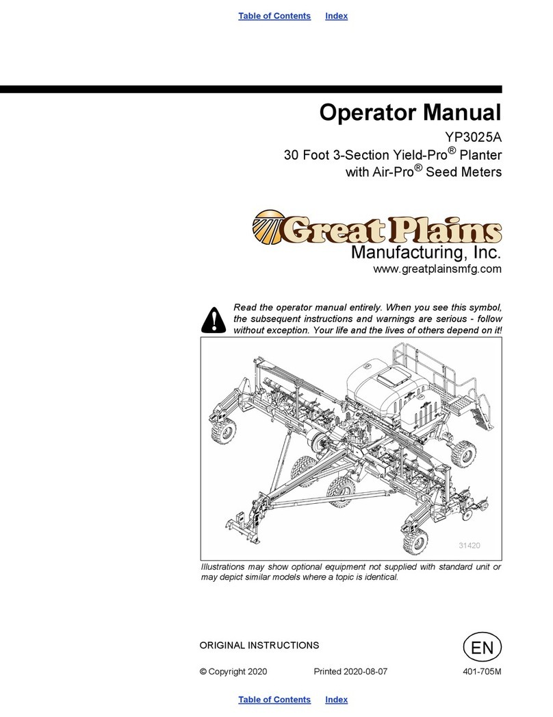
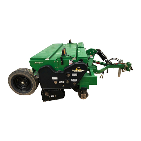
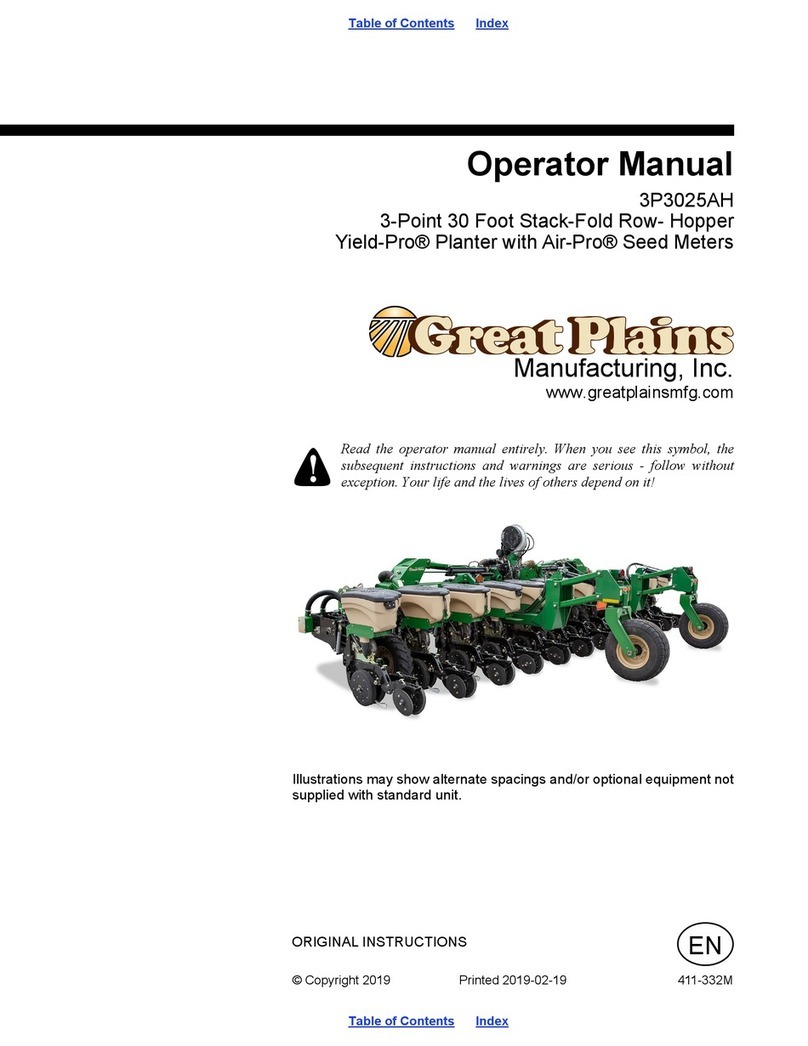
GREAT PLAINS Yield-Pro 3P3025AH User manual

Manufacturing, Inc.
www.greatplainsmfg.com
© Copyright 2016 Printed 2016-12-21 411-332Q
EN
Table of Contents
Table of Contents
ORIGINAL INSTRUCTIONS
Pre-Delivery Manual
3P3025AH
3-Point 30 Foot Stack-Fold Row- Hopper
Yield-Pro® Planter with Air-Pro® Seed Meters
Read the operator manual entirely. When you see this symbol, the
subsequent instructions and warnings are serious - follow without
exception. Your life and the lives of others depend on it!
Illustrations may show alternate spacings and/or optional equipment not
supplied with standard unit.

Table of Contents
Table of Contents

411-332Q Cover 1
2016-12-21 Cover 411-332Q
© Copyright 2015, 2016 All rights Reserved
Great Plains Manufacturing, Inc. provides this publication “as is” without warranty of any kind, either expressed or implied. While every precaution has been
taken in the preparation of this manual, Great Plains Manufacturing, Inc. assumes no responsibility for errors or omissions. Neither is any liability assumed
for damages resulting from the use of the information contained herein. Great Plains Manufacturing, Inc. reserves the right to revise and improve its products
as it sees fit. This publication describes the state of this product at the time of its publication, and may not reflect the product in the future.
Trademarks of Great Plains Manufacturing, Inc. include:AccuShot, Max-Chisel, Row-Pro,
Singulator Plus, Short Disk, Swath Command, Terra-Tine, Ultra-Chisel, and X-Press.
Registered Trademarks of Great Plains Manufacturing, Inc. include:Air-Pro, Clear-Shot, Discovator, Great Plains, Land Pride, MeterCone,
Nutri-Pro, Seed-Lok, Solid Stand, Terra-Guard, Turbo-Chisel, Turbo-Chopper, Turbo-Max, Turbo-Till, Ultra-Till, Whirlfilter, and Yield-Pro.
Brand and Product Names that appear and are owned by others are trademarks of their respective owners.
Printed in the United States of America
Table of Contents
Important Safety Information.................................................1
Introduction.............................................................................5
Document Family .......................................................5
Intended Usage.................................................................5
Using This Manual.............................................................5
Models Covered ................................................................5
Description of Unit.............................................................5
Definitions...................................................................6
Owner Assistance..............................................................6
Further Assistance.............................................................6
Assembly.................................................................................7
Tools Required..................................................................7
Pre-Assembly Checklist.....................................................7
Pre-Delivery.............................................................................8
Front Gauge Wheel Installation.......................................10
Raising the Drill...............................................................11
Wings: Do Not Lift with Hoist or Forklift....................11
3-Point Hitch Lifting Adapter ....................................11
Unloading........................................................................13
Lift Assist Wheel Installation............................................14
Gullwing Switch Adjustment Without Lift Assist ..............15
Gullwing Switch Adjustment With Lift Assist ...................16
Seeding Switch, Planters With Hydraulic Drive...............17
Planters Without Rear Lift Assist..............................17
Planters With Rear Lift Assist...................................18
Torque Values Chart.......................................................19
Tire and Wheel Information.............................................20

2016-12-21 Table of Contents 411-332Q
3P3025AH Table of Contents 1
Important Safety Information
Look for Safety Symbol
The SAFETY ALERT SYMBOL indicates there is a
potential hazard to personal safety involved and extra
safety precaution must be taken. When you see this
symbol, be alert and carefully read the message that
follows it. In addition to design and configuration of
equipment, hazard control and accident prevention are
dependent upon the awareness, concern, prudence and
proper training of personnel involved in the operation,
transport, maintenance and storage of equipment.
Be Aware of Signal Words
Signal words designate a degree or level of hazard
seriousness.
DANGER indicates an imminently hazardous situation
which, if not avoided, will result in death or serious injury.
This signal word is limited to the most extreme situations,
typically for machine components that, for functional
purposes, cannot be guarded.
WARNING indicates a potentially hazardous situation
which, if not avoided, could result in death or serious
injury, and includes hazards that are exposed when
guards are removed. It may also be used to alert against
unsafe practices.
CAUTION indicates a potentially hazardous situation
which, if not avoided, may result in minor or moderate
injury. It may also be used to alert against unsafe
practices.
Prepare for Emergencies
Be prepared if a fire starts
Keep a first aid kit and fire extinguisher handy.
Keep emergency numbers for doctor, ambulance, hospital
and fire department near phone.
Be Familiar with Safety Decals
Thoroughly read and understand “Safety Decals”
starting on page 6 of the 411-332M Operator Manual.
Read all instructions noted on the decals.
Keep decals clean. Replace damaged, faded and illegible
decals.

2016-12-21 Table of Contents 411-332Q
3P3025AH Table of Contents Important Safety Information 2
Wear Protective Equipment
Wear protective clothing and equipment.
Wear clothing and equipment appropriate for the job.
Avoid loose-fitting clothing.
Because prolonged exposure to loud noise can cause
hearing impairment or hearing loss, wear suitable
hearing protection such as earmuffs or earplugs.
Because operating equipment safely requires your full
attention, avoid wearing entertainment headphones while
assembly or operating machinery.
Use A Safety Chain
Use a safety chain to help control drawn machinery
should it separate from tractor draw-bar.
Use a chain with a strength rating equal to or greater than
the gross weight of towed machinery.
Attach chain to tractor draw-bar support or other
specified anchor location. Allow only enough slack in
chain to permit turning.
Replace chain if any links or end fittings are broken,
stretched or damaged.
Do not use safety chain for towing.
Avoid High Pressure Fluids
Escaping fluid under pressure can penetrate the skin,
causing serious injury.
Avoid the hazard by relieving pressure before
disconnecting hydraulic lines.
Use a piece of paper or cardboard, NOT BODY PARTS, to
check for suspected leaks.
Wear protective gloves and safety glasses or goggles when
working with hydraulic systems.
If an accident occurs, seek immediate medical assistance
from a physician familiar with this type of injury.
Minimize Radiation Exposure
The radar is an intentional radiator of RF energy.
Although its radiated energy level is far below the limits
set by EN 61010-1:1993 A2:1995-Chapter 12.4, it is
advisable not to look directly into the face of the unit.
The radar must radiate toward the ground and at least 20
cm (8 inches) away from a human during use to comply
with the RF human exposure limits as called out in
FCC 47 CFR Sec.2.1091. DO NOT RE-MOUNT OR
USE THE RADAR IN A MANNER INCONSISTENT
WITH ITS DEFINED USE.

3P3025AH Table of Contents Important Safety Information 3
2016-12-21 Table of Contents 411-332Q
Tire Safety
Tire changing can be dangerous and should be
performed by trained personnel using correct tools and
equipment.
When inflating tires, use a clip-on chuck and extension
hose long enough for you to stand to one side–not in front
of or over tire assembly. Use a safety cage if available.
When removing and installing wheels, use wheel-handling
equipment adequate for weight involved.
Use Safety Lights and Devices
Slow-moving tractors and towed implements can create
a hazard when driven on public roads. They are difficult
to see, especially at night.
Use flashing warning lights and turn signals whenever
driving on public roads.
Use lights and devices provided with implement
Keep Riders Off Machinery
Riders obstruct the operator’s view. Riders could be
struck by foreign objects or thrown from the machine.
Never allow children to operate equipment.
Keep all bystanders away from machine during operation.
Transport Machinery Safely
Maximum transport speed for implement is 30 kph or
20 mph. Some rough terrains require a slower speed.
Sudden braking can cause a towed load to swerve and
upset.
Do not exceed 30 kph or 20 mph. Never travel at a speed
which does not allow adequate control of steering and
stopping. Reduce speed if towed load is not equipped with
brakes.
Comply with state and local laws.
Do not tow an implement that, when fully loaded, weighs
more than 1.5 times the weight of towing vehicle.
Carry reflectors or flags to mark drill in case of
breakdown on the road.
Keep clear of overhead power lines and other
obstructions when transporting. Refer to transport
dimensions under “Specifications and Capacities” in
Operator manual.
Do not fold or unfold the drill while the tractor is moving
Shutdown and Storage
Unfold and lower drill.
Block tires or use optional drill parking brakes.
Detach and store drill in an area where children normally
do not play.

2016-12-21 Table of Contents 411-332Q
3P3025AH Table of Contents Important Safety Information 4
Practice Safe Maintenance
Understand procedure before doing work. Use proper
tools and equipment. Refer to this manual. For brake
work, see specific safety information in the Operator
manual.
Work in a clean, dry area.
Unfold and lower the drill, put tractor in park, turn off
engine, and remove key before performing maintenance.
Make sure all moving parts have stopped and all system
pressure is relieved.
Allow drill to cool completely.
Disconnect battery ground cable (-) before servicing or
adjusting electrical systems.
Welding: Disconnect battery ground. Protect hydraulic
lines. Avoid fumes from heated paint.
Inspect all parts. Make sure parts are in good condition
and installed properly.
Remove buildup of grease, oil or debris.
Remove all tools and unused parts from drill before
operation.
Safety At All Times
Thoroughly read and understand the instructions in this
manual before operation. Read all instructions noted on
the safety decals.
Be familiar with all drill functions.
Operate machinery from the driver’s seat only.
Do not leave drill unattended with tractor engine running.
Do not stand between the tractor and drill during
hitching.
Keep hands, feet and clothing away from power-driven
parts.
Wear snug-fitting clothing to avoid entanglement with
moving parts.
Watch out for wires, trees, etc., when folding and raising
drill. Make sure all persons are clear of working area.

2016-12-21 Table of Contents 411-332Q
3P3025AH Table of Contents 5
Introduction
Great Plains welcomes you to its growing family of new
product owners. The Full Product Name (3P3025AH)
has been designed with care and built by skilled workers
using quality materials. Proper setup, maintenance, and
safe operating practices will help you get years of
satisfactory use from the machine.
Models Covered
Description of Unit
The 3P3025AH drill is a 3-point mounted seeding
implement for use in conventional and minimum tillage
conditions. The three section stack-folding tool bar has a
working width of 30 feet (9.14 m).
Planters with ground drive use A DICKEY-john PM400
seed monitor. Planters with hydraulic drive use a
DICKEY-john AI-120 monitor.
Row units are equipped with 25 Series double-disc
openers, side depth wheels, Air-Pro seed meters, with
seed gravity fed by 1.6 bushel (56 liter) or 3.0 bushel
(105 liter) hoppers. Frame options include lift assist, wing
flex, and wing lock. Row options available include row
cleaners, coulters, seed firmers, scrapers, press wheels
and drags.
30-foot single-row models
Product #2315 23-row, 15 inch spacing
Product #1820 18-row, 20 inch spacing
Product #1622 16-row, 22 inch spacing
Product #1230 12-row, 30 inch spacing
Product #0836 8-row, 36 inch spacing
Product #0838 8-row, 38 inch spacing
Product #0840 8-row, 40 inch spacing
Product #1270 12 row, 70 cm spacing
30-foot twin row models
Product #2430 24 row, 30 in. pair spacing
Product #1636 16 row, 36 in. pair spacing
Product #1638 16 row, 38 in. pair spacing
Product #1640 16 row, 40 in. pair spacing
Figure 1
3P3025AH Planter 38342
Document Family
Intended Usage
Use the 3P3025AH Drill to seed production agriculture
crops only. Do not modify the planter for use with
attachments other than Great Plains options and
accessories specified for use with the Product.
Using This Manual
This manual will familiarize you with safety, assembly,
operation, adjustments, troubleshooting, and
maintenance. Read this manual and follow the
recommendations to help ensure safe and efficient
operation.
The information in this manual is current at printing.
Some parts may change to assure top performance.
411-332Q Pre-delivery Manual (this document)
411-332M Operator Manual
411-099B Seed Rate Manual
411-332P Parts Manual
11001-1372 DICKEY-john PM400 Operator’s Manual
401-909M DICKEY-john Quick AI-120 Reference Guide
110011606 DICKEY-john AI-120 VT Manual

2016-12-21 Table of Contents 411-332Q
3P3025AH Table of Contents Introduction 6
Definitions
The following terms are used throughout this manual.
Right-hand and left-hand as used in
this manual are determined by facing
the direction the machine will travel
while in use unless otherwise stated.
An orientation rose in some line art
illustrations shows the directions of:
Up, Back, Left, Down, Front, Right.
Outcome to Avoid:
A crucial point of information related to the current topic.
Read and follow the directions to remain safe, avoid serious
damage to equipment and ensure desired field results.
Useful information related to the preceding topic.
Owner Assistance
If you need customer service or repair parts, contact a
Great Plains dealer. They have trained personnel, repair
parts and equipment specially designed for Great Plains
products.
Refer to Figure 2
Your machine’s parts were specially designed and
should only be replaced with Great Plains parts. Always
use the serial and model number when ordering parts
from your Great Plains dealer. The serial-number plate is
located in front, above the left-hand lower 3-point hitch.
Record your Drill model and serial number here for quick
reference:
Model Number:__________________________
Serial Number: __________________________
Further Assistance
Great Plains Manufacturing, Inc. wants you to be
satisfied with your new product. If for any reason you do
not understand any part of this manual or are otherwise
dissatisfied, please contact:
Great Plains Service Department
1525 E. North St.
P.O. Box 5060
Salina, KS 67402-5060
Or go to www.greatplainsag.com and follow the contact
information at the bottom of your screen for our service
department.
U
D
F
B
L
R
Figure 2
Serial Number Plate 38339

2016-12-21 Table of Contents 411-332Q
3P3025AH Table of Contents 7
Assembly
The following headings are step-by-step instructions for
assembling the 3P3025AH Planter. Begin with “Tools
Required” and “Pre-Assembly Checklist” to make sure
you have all necessary parts and equipment. Follow
each step to make the job as quick and safe as
possible and produce a properly working machine.
The 3P3025AH Planter is shipped via flat bed truck. It is
the dealer’s responsibility to unload the new machine.
Pre-Assembly Checklist
1. Before assembling, read and understand
“Important Safety Information,” page 1.
2. Have at least two people on hand while
assembling.
3. Make sure assembly area is solid, level, and free of
obstructions (preferably an open concrete area).
4. Make sure that after unloading there is room
enough to connect a tractor to the planter and pull
the planter away.
5. Have all major components.
6. Have all fasteners and pins that were shipped with
3P3025AH Planter.
If a pre-assembled part or fastener is temporarily removed,
remember where it goes. Keep the parts separated.
7. Have a copy of the parts manual on hand. If unsure
of proper placement or use of any part or fastener,
refer to the parts manual.
8. Check that all working parts are moving freely, bolts
are tight, and cotter pins are spread.
9. Check for proper tension and alignment on all drive
chains.
10. Check that all safety decals and reflectors are
located correctly and legible. Replace if improperly
located or damaged. See “Safety Decals” in the
operator’s manual.
11. Inflate tires to recommended pressure as listed on
the “Tire and Wheel Information,” page 20.
12. Tighten wheel bolts as specified in “Torque Values
Chart.” page 19.
Tools Required
•General hand tools
•Unloading the planter with one forklift.
Use a 3-point hitch adapter that fits the planter and
the forklift. The capacity of the forklift must be
7257 kg. (16 000 lb) or greater.
•Unloading the planter using three forklifts.
The total capacity of the forklifts must be 7257 kg.
(16 000 lb) or greater.
The forklift used at the front of the planter must
have a capacity of 4310 kg (9500 lb) or greater.
The two forklifts used at the rear of the planter
must have a capacity of 1474 kg (3250 lb) each.

2016-12-21 Table of Contents 411-332Q
3P3025AH Table of Contents 8
Pre-Delivery
Plan the Unload
Unloading the planter can be a safe, smooth operation if
it is properly planned in advance.
Scope the lift equipment and team size required.
Make sure there is room after lowering the planter to
connect a tractor to the planter.
If the planter does not have lift assist, install the gauge
wheels on the front of the planter before unloading.
If the planter has lift assist, install the rear gauge wheels
after the planter is unloaded.
Review the steps with all lift team members.
For multiple lifters, gather lifters and practice
simultaneous lift. Learn control operations for equal lift
rates.
Designate an observer to be lift leader.
Have an agreed signalling or command for simultaneous
halting of the lift if any team member detects a problem.
Release any straps or chains securing the planter to the
trailer bed.
Lift the product and move the trailer, not the drill.
Lifting Equipment
If the planter does not have lift assist, install the gauge wheels
on the front of the planter before unloading the planter.
If the planter has lift assist, do not install the gauge wheels on
the rear of the planter until the planter is removed from the
trailer.
Unloading with 3-Point Hitch Lifting Adapter
Attach the forklift 3-point adapter to the 3-point hitch
points on the planter. The forklift must be rated for
7257 kg (16 000 lb) or higher.
Unloading with Fork Lifts
Use three forklifts with a combined capacity of 7257 kg
(16 000 lb) or higher.
Do not use less than three forklifts. There is one lift point
on the front and two lift points on the rear.
Capacity of front forklift: 4310 kg (9500 lb) or greater.
Capacity of two rear forklifts combined: 2948 kg (6500 lb)
or greater. Minimum of 1474 kg (3250 lb) each.
When using multiple forklifts, do not assume that each
lifter has an equal amount of the load. Plan excess
capacity. Monitor load indicators and overload
indications or alarms.
> 14,000
POUNDS

3P3025AH Table of Contents Pre-Delivery 9
2016-12-21 Table of Contents 411-332Q
Location Requirements
Until unloaded, the planter cannot be moved using a
tractor. The mainframe needs to be unloaded directly
above the spot where final assembly takes place.
This location needs to be:
•solid, level ground or pavement -
the parking stand loads can approach 100 psi
•there must be adequate space to pull the trailer out
from under the lifted mainframe, without turns,
•there must be adequate space at the front and rear
of the planter to easily maneuver forklifts
•there must be adequate space in front of the drill to
attach a tractor and move forward for delivery.
Mark the parking location with traffic cones or pavement
markers.
Figure 3
Suggested Unload Clearances
40ft
150ft

2016-12-21 Table of Contents 411-332Q
3P3025AH Table of Contents Pre-Delivery 10
Front Gauge Wheel Installation
If the planter does not have rear lift assist, the gauge wheels are mounted on the front of the planter. Install the gauge wheels on
the planter before unloading the planter from the trailer.
Before installing the gauge wheel assemblies, check the area above the mounting weldment for a gullwing switch.
Refer to Figure 4.
a. If the planter has a gullwing switch in this location, remove the mounting hardware from the gullwing switch.
b. Set the gullwing switch aside to prevent damage during installation of the gauge wheel assembly.
c. After the planter is on the ground, install and adjust the gullwing switch for the gauge wheel. See “Gullwing
Switch Adjustment Without Lift Assist” on page 15.
Refer to Figure 4
1. Install the wheel on the hub .
2. Install the wheel bolts .
3. On the removable arm loosen, but do not remove,
the cap screw in the spindle nut lock wrench .
4. Raise the wheel to put the removable arm in the
mounting position.
5. Loosely install the two RHSN bolts . Install the two
lock washers and then the two nuts on each
RHSN bolt.
6. Install the lock washer and the cap screw in
the end of the spindle.
7. Install the spindle nut lock wrench on the lock nuts
on the spindle.
8. Tighten the cap screw in the spindle nut lock wrench.
Tighten the RHSN bolts in the removable arm.
9. Remove the two cap screws and sleeves from
the sides of the adjustment linkage .
10. Align the adjustment linkage with the mounting holes
in the wheel mounting weldment. Install the sleeves
and the cap screws. Tighten the cap screws.
11. After the planter is on the ground and connected to a
tractor, adjust the gullwing switch for the gauge
wheels. See “Gullwing Switch Adjustment
Without Lift Assist” on page 15.
7
4
5
6
3
10
14 13
15
1
10
11
10
12
9
8
2
Figure 4
Front Gauge Wheel Installation 38744
1
2
3
4
5
6
7
8
9
10
11
12
13
14
15

3P3025AH Table of Contents Pre-Delivery 11
2016-12-21 Table of Contents 411-332Q
Raising the Drill
Wings: Do Not Lift with Hoist or Forklift
Refer to Figure 5
Lift only by the center section.
Lift Failure Hazard:
Do not lift on the wings outboard of the lock-down pins. There
is significant risk of hinge failure and lift collapse, with
possible serious injury or death, and major damage to both
drill and lift equipment.
The folding/stacking wings of the product must not be
used for lifting. Although they are shipped in the
pinned-down configuration, the hinge/arm system is
designed only to carry the weight of the wings, and not
the center section.
3-Point Hitch Lifting Adapter
Refer to Figure 6
Attach the forklift 3-point adapter to the 3-point hitch
points on the planter.
Do not use a forklift on the 3-point hitch points without using a
3-point adapter.
See “Unloading” on page 13.
Figure 5
No-Lift/No-Hoist Areas 38342C
Figure 6
3-Point Hitch Adapter 38342C
1
1

2016-12-21 Table of Contents 411-332Q
3P3025AH Table of Contents Pre-Delivery 12
Three Fork Lifts
Refer to Figure 7
If the planter has rear assist lift, make sure the rear gauge
wheels and linkage have not been installed.
Use three forklifts with a combined capacity of 7257 kg
(16 000 lb) or higher
Do not use less than 3 forklifts. There is one lift point on
the front and two lift points on the rear.
Capacity of front forklift: 4310 kg (9500 lb) or greater.
Capacity of two rear forklifts combined: 2948 kg (6500 lb)
or greater. Minimum of 1474 kg (3250 lb) each.
When using multiple forklifts, do not assume that each
lifter has an equal amount of the load. Plan excess
capacity. Monitor load indicators and overload
indications or alarms.
Position the fork lift with the highest capacity at the
center of the frame front. Lift at the center frame side
tubes.
Position the other two fork lifts to support the lift assist
frames.
Unbalanced Load Risk:
Two observers are needed, one for front-back level, and the
other for side-to-side.
The observers need to pay close attention to drill level, and
signal each lift operator how to compensate if imbalance is
detected.
See “Unloading” on page 13.
Figure 7
Three Forklifts 38342C

3P3025AH Table of Contents Pre-Delivery 13
2016-12-21 Table of Contents 411-332Q
Unloading
Have the driver spot the truck as marked during
See “Plan the Unload” on page 8.
Unload Smaller Items First
If the planter does not have rear lift assist, make sure the front
gauge wheels are installed on the planter.
Unloading the planter is a potentially dangerous
operation.
Reduce risk and complication by first unloading any
miscellaneous crates.
Place these components well out of the maneuvering
area needed for unloading the planter.
Unload The Planter
1. Double-check that all chains and tie-down straps
have been released and stowed.
2. If the planter does not have rear lift assist, make sure
the front gauge wheels are installed on the planter.
3. Make sure that all team members are fully briefed
and ready.
4. Set parking brake on trailer tractor.
5. Put the lifting equipment in position. See “Raising
the Drill” on page 11.
Lifter-Trailer Contact Risk:
Do not move the fork lifts or crane so far in that trailer wheels
will not be able to clear them when pulling trailer out from
under drill.
Load “Wedging” Risk:
If using multiple fork lifts, do not drive the fork lifts fully
forward into the drill, unless the fork lifts are known to have
precisely vertical motion. If the load moves forward while
lowering, the drill will tend to push the fork lifts backward.
6. Slowly lift the drill off the trailer bed.
7. Stop lifting about 12in above the bed.
8. Have the truck driver slowly pull the trailer straight
out from under the drill.
9. Making sure to keep level from front to back and side
to side, slowly lower the drill to the ground.
10. Lower forks and withdraw fork lifts.

2016-12-21 Table of Contents 411-332Q
3P3025AH Table of Contents Pre-Delivery 14
Lift Assist Wheel Installation
Refer to Figure 8
If the planter has rear lift assist, do not install the gauge
wheels until after the planter is unloaded from the trailer.
Before installing the lift assist wheel assemblies,
a. Find the extension on the rear of the
mainframe used for mounting gullwing
switch .
b. Remove the hardware from the gullwing switch.
Move the gullwing switch away from the
mounting plate to prevent damage when
installing the lift assist wheel assembly.
c. Check the upper tube of the parallel arm
assemblies for a switch cam .
d. Make sure the lift assist wheel assembly with
the cam is installed to the frame extension with
the gullwing switch.
e. After the planter is on the ground, install and
adjust the gullwing switch. See “Gullwing
Switch Adjustment With Lift Assist” on
page 16
Refer to Figure 9
1. Remove the cap screws , flat washers , lock
washers , and nuts stored in the pivot tubes in
the loose ends of the parallel arms .
2. Remove the pivot tubes from the ends of the parallel
arms. Make sure the bushings stay in the parallel
arms.
3. Use a hoist to lift the lift assist wheel assembly into
position. Make sure the rod end of the lift cylinder is
out of the way.
4. Align the lower parallel arm with the lower holes in
the lift assist extension weldment.
5. Install the pivot tube.
6. Install the bolt, flat washer, lock washer, and the nut.
7. Repeat the procedure for the upper parallel arm.
8. Remove the hairpin and the clevis pin from the
clevis at the rod end of the lift cylinder. Make sure the
bushings are still in the clevis.
9. Install the cylinder clevis on the mounting ear in the
caster wheel assembly. Install the clevis pin and the
hairpin.
10. After the planter is connected to a tractor, install and
adjust the gullwing switch. See “Gullwing Switch
Adjustment With Lift Assist” on page 16
Figure 8
Gullwing Switch and Switch Cam 38481
12
43
1
2
3
4
1
Figure 9
Lift Assist Wheel Installation 38743
1
4
3
27
8
5
6
1
2
3
4
5
6
7
8

3P3025AH Table of Contents Pre-Delivery 15
2016-12-21 Table of Contents 411-332Q
Gullwing Switch Adjustment Without
Lift Assist
Refer to Figure 10
1. Hitch the planter to a tractor.
2. Put the planter in the field position.
3. Raise the planter.
4. Apply the tractor parking brake and stop the
engine. Take the key with you to prevent
unauthorized starting.
5. Loosen the cap screws that hold the gullwing
switch .
6. Raise the gullwing switch all the way.
7. Slowly lower the gullwing switch until roller
contacts the plate .
8. Continue to lower the gullwing switch until you hear
the internal contacts move.Approximately 1/8 inch.
9. Hold the gullwing switch in position and carefully
tighten the cap screws.
1
2
4
3
Figure 10
Gullwing Switch at Gauge Wheel 38559
1
2
3
4

2016-12-21 Table of Contents 411-332Q
3P3025AH Table of Contents Pre-Delivery 16
Gullwing Switch Adjustment With
Lift Assist
Refer to Figure 11
1. Hitch the planter to a tractor.
2. Lower the lift assist to the point where you want the
wings to start raising. The row units should be just
off the ground.
3. Apply the tractor parking brake and stop the
engine. Take the key with you to prevent
unauthorized starting.
4. Loosen the bolt in the switch cam .
5. Rotate the switch cam until the roller on the
gullwing switch is on the high area of the switch
cam.
6. Tighten the bolt in the switch cam.
7. Loosen the bolts in the gullwing switch.
8. Raise the gullwing switch. Slowly lower the lift
assist switch to the point where you hear the
internal contacts move. Hold gullwing switch and
carefully tighten the bolts.
Refer to Figure 12
9. Loosen the bolt in the switch cam .
10. Rotate the top of the switch cam rearward until the
roller is just at the bottom of the ramp leading up
to the high area on the switch cam.
11. Tighten the bolt in the switch cam.
12. Before checking the adjustment, put an alignment
marks on the switch cam and the shaft . If
adjustment is necessary, this will allow you to see
how far you have rotated the cam.
13. Test the operation of the gullwing switch.
If the wings move too early, the top of the switch
cam must be rotated a small amount toward the
rear.
If the wings move too late, the top of the switch cam
must be rotated a small amount toward the front.
14. Apply the tractor parking brake and stop the
engine. Take the key with you to prevent
unauthorized starting.
15. Loosen the clamp bolt for the switch cam.
16. Carefully rotate the switch cam as necessary.
17. Tighten the clamp bolts.
18. Test the operation of the gullwing switch again and
adjust the switch cam as necessary.
19.
Figure 11
Gullwing Switch on High Area of
Switch Cam
38481
1
53
4
2
1
2
3
4
Figure 12
Gullwing Switch at Beginning of
Ramp on Switch Cam
23481
4
3
1
2
1
2
3
4

3P3025AH Table of Contents Pre-Delivery 17
2016-12-21 Table of Contents 411-332Q
Seeding Switch, Planters With Hydraulic Drive
Planters Without Rear Lift Assist
Refer to Figure 13
The seeding switch signals the seed monitor when
the drill is lowered for planting. If the drill has hydraulic
drive for the row units, the seeding switch also activates
the hydraulic drive.
Great Plains recommends adjusting the seeding switch
for your exact field conditions and planting depth.
Check the seeding switch seasonally thereafter, or
when planting conditions change. Also perform this
adjustment if the seeding switch is replaced or
dislodged.
The switch bracket uses a magnet for mounting.
The seeding switch must be mounted where the toggle
arm is actuated by the lift arms on the tractor.
When installing, adjusting, or replacing the seeding
switch, make sure the cable exit is at the bottom. If
the cable exit is at the top, moisture will accumulate in
the seeding switch, causing failure.
1. Put the planter in the field position.
2. Lower the drill to the height at which seed delivery
is to begin.
3. Apply the tractor parking brake, stop the engine,
and take the key with you.
4. Find a location where the switch bracket can be
mounted with the magnet. The toggle arm must be
actuated by the lift arms on the tractor while
planting. the toggle switch must be free of the lift
arms when the planter is raised by the 3-point
arms.
5. Slide the switch bracket to move seeding switch up
or down. Adjust switch bracket so toggle arm just
makes contact with tractor 3-point lift arms.
6. Move the switch bracket down 1/4inch (6.4 mm).
1
52
4
3
Figure 13
Seeding Switch 68092
1
2
3
4
5
Other manuals for Yield-Pro 3P3025AH
3
Table of contents
Other GREAT PLAINS Seeder manuals

GREAT PLAINS
GREAT PLAINS 2020P User manual

GREAT PLAINS
GREAT PLAINS Turbo Max 2400TM User manual

GREAT PLAINS
GREAT PLAINS YP1225A User manual

GREAT PLAINS
GREAT PLAINS YP-40 Series User manual

GREAT PLAINS
GREAT PLAINS BD7600 User manual

GREAT PLAINS
GREAT PLAINS Yield-Pro 3P3025AH User manual

GREAT PLAINS
GREAT PLAINS CTA4000HD User manual

GREAT PLAINS
GREAT PLAINS YP3025A User manual

GREAT PLAINS
GREAT PLAINS YP-30 Series User manual

GREAT PLAINS
GREAT PLAINS YP2425F-2470 Owner's manual