Green Brook TH90-C User manual
For the correct working and safety reasons these thermostats
must be installed and used according to the instructions.
The thermostats are mainly suitable for heating and air
conditioning installations. The thermostats have been tested
in compliance with the european standards for safety.
Imp rtant: This product should be installed by a competent
person and in accordance with the current IET Wiring
Regulations. If in doubt, consult a qualified electrician.
IN TALLATION
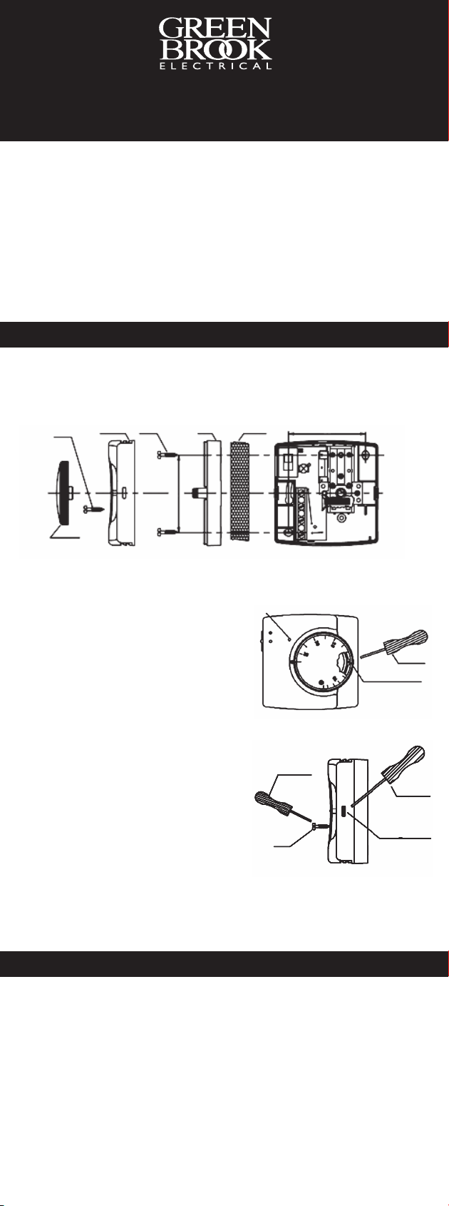
The room thermostats can be installed directly on the wall by
means of screws securing the holes of the thermostats base
after the removing the knob and the cover (see Dia 1.).
Dia 1.
crew
Top Cover crews Base Wall 61
19
To remove the knob.
Turn the knob to the maximum
position. Insert a blade of a
screwdriver in the fissure between
the knob and the top cover. Use
the screwdriver as a lever to
remove the knob. (See Dia 2).
To remove the top cover.
Remove the screw on the top
cover. ress slightly with a
screwdriver blade on the fixing
hook. (See Dia 3).
Pilot Lamp
crewdriver
Fissure for
screwdriver
Dia 2.
We recommend to install the room thermostat at the height
of approx 1.5m from the ground. away from any heat sources
and avoiding humid and polluted environments.
Dia 3.
crewdriver
Fixing Hook
crew
crewdriver
CONNECTION
Before proceeding with electrical connection disconnect
mains. The electrical connection is ensured by the means of
screw terminals. Max cable diameter 2.5mm2.
The thermostats are equipped with an accelerating
resistance which must be connected to the mains in order
to ensure the indicated control performances. Terminal 4
should therefore be connected to neutral according to the
wiring diagram. This connection will also allow the pilot lamp
to light up to indicate that the unit is operating. See over for
wiring diagram 4.
Installation/Operating Instruction for
Room Thermostats
- TH90-C, TH90F-C & TH90C-C
TH90 TH90F TH90C Ins.qxp_Layou 1 13/03/2017 12:35 Page 1

TECHNICAL INFORMATION
Temperature Range: 5°/15°C 5°/35°C
Temperature Differential: <1°C
Max Operating Temp: 50°C
Storage Temperature: -30 / 70°C
Number of Cycles: 200,000
Electrical Values of opening: 10(2)A 250V
Electrical Values of closing: Version TH90C 3(1)A 250V
Degree of rotection: I 20
Type of disconnection: Micro disconnection
(Single pole)
CONDITIONS OF USE
Knob Index
Decrease
Increase
Dia 5.
Dia 4.
Temperature scale adjustment (if required). roceed as
follows to obtain an accurate indication of the room
temperature, approximately two days after the installation
measure the room temperature with a thermometer.
Compare the difference between the temperature reading
on the thermometer and the temperature indicated by the
knob index, remove the knob and the knob base. Turn the
base clockwise (to decrease) or anticlockwise (to increase)
in order to eliminate any difference in temperature between
the thermometer reading and the knob index. One notch =
1°C (see Dia 5.). Replace the knob base first and then the
knob.
T1 - T 3 10 (2)A 25 0V
T1 - T 2 3(1)A 25 0V
< 9
LN
T1 - T3 10(2)A 250V
< 9
1
2
3
4
1
2
3
4
LN
M
M
TH90 & TH90F - With
normally closed contact
(S ST)
TH90C - With changeover
contact (S DT)
Issue no: 704736
WE T ROAD . HARLOW
E EX . CM20 2BG . UK
info@greenbrook.co.uk
www.greenbrook.co.uk
PLEA E KEEP THE E IN TRUCTION
AFE FOR FUTURE REFERENCE
GUARANTEE
Y ur GreenBr k R m Therm stat TH90,
TH90C & TH90F is guaranteed f r 1 year
fr m the date f purchase.
This is in additi n t y ur statut ry rights.
TH90 TH90F TH90C Ins.qxp_Layou 1 13/03/2017 12:35 Page 2
This manual suits for next models
2
Table of contents
Other Green Brook Thermostat manuals


Popular Thermostat manuals by other brands


Sygonix
Sygonix tx.1 operating instructions

Atag
Atag BrainQ RSC/2 installation manual

Salus
Salus OPTIMA ZigBee quick start guide

Saswell
Saswell SAS918WHB-0-RF User manual and warranty card

White Rodgers
White Rodgers 90 SERIES 1F95-391 operating instructions

Venstar
Venstar T3900 Installation instructions and owner's manual


