IBCI BLACK DIAMOND
User's Manual
xx.x V xxx A
xxx Ah x.x t
The Black Diamond Charger performs an exclusive charge cycle that is composed by stages
at constant current and stages at pulsed current, with cool down pauses in between.
The management of the charging curve is totally automatic.
Depending on the programming of the Full Charge time window (Parameter 9), when the
battery approaches the gassing voltage the charger may suspend the charge (typical
opportunity charge cycle). In this situation, the display visualizes the message:
DELAYED OVERCH.
(hh.mm)A →(hh.mm)B
Where (hh.mm)A represents the real time at that moment, and (hh.mm)B represents the
beginning of the Full Charge / Overcharge time window.
During the cool down pauses, that are normally inserted during the gassing phase, the
display visualizes the message “Cooling”.
xx.x V Cooling
xxx Ah x.x t
E
MER
G
ENC
Y
STOP
If the battery doesn't reach the gassing voltage within a predetermined time, the charger will
suspend the charge, and it will visualize the message
EMERGENCY STOP
VGAS NOT REACHED
In this case, the charge cannot proceed, and it's necessary to disconnect the battery.
It's recommended to control the battery for damaged cells.
The Black Diamond Charger performs an exclusive charge cycle that is composed
by stages at constant current and stages at pulsed current, with cool down pauses
in between. The management of the charging curve is totally automatic.
Depending on the programming of the Full Charge time window (Parameter 9), when
the battery approaches the gassing voltage the charger may suspend the charge
(typical opportunity charge cycle). In this situation, the display visualizes the message:
Where (hh.mm)A represents the real time at that moment, and (hh.mm)B represents
the beginning of the Full Charge / Overcharge time window.
During the cool down pauses, that are normally inserted during the gassing phase,
the display visualizes the message “Cooling”.
EMERGENCY STOP
If the battery doesn’t reach the gassing voltage within a predetermined time, the
charger will suspend the charge, and it will visualize the message:
In this case, the charge cannot proceed, and it’s necessary to disconnect the battery.
It’s recommended to control the battery for damaged cells.
AC INPUT BLACK OUT
If there is a black-out of the AC input, while the charge is in progress, the charger
will shut down, while the charge parameters will remain in memory.
When the AC input will be recovered, the charger will restart the charge cycle
automatically, and the display will show the message:
OVERCURRENT PROTECTION
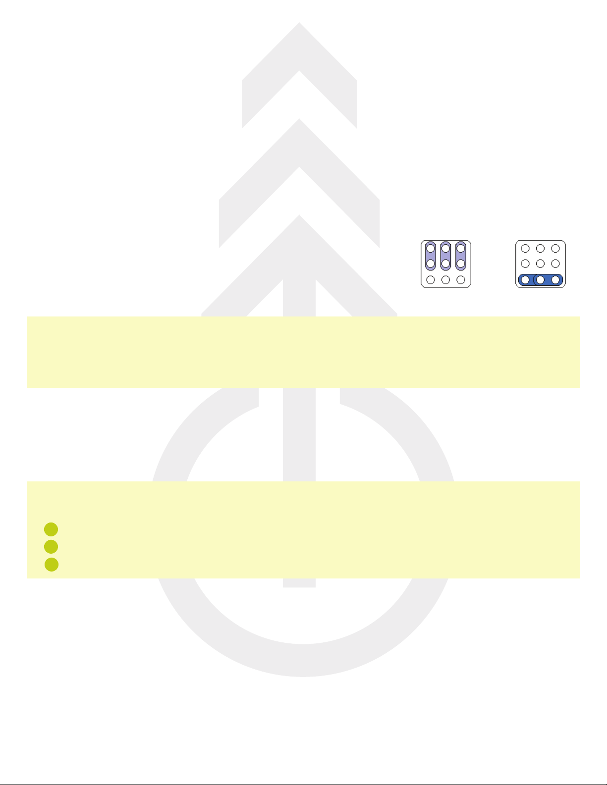
If the AC input voltage is abnormally high and/or the AC input adjustments have not
been done correctly (See Chapter “INSTALLATION”), the charging current may
reach an excessive value.
In this case, the charger will suspend the charge, and the display will visualize
the message:
The charge will not proceed, and it’s necessary to disconnect the battery.
It’s recommended to control the AC input connections of the charger,
as explained in Chapter 3 “INSTALLATION”.
It’s recommended to verify the condition of the battery, as it may have one or more cells in short circuit.
AUTOMATIC STOP
The charger shuts down automatically when the charge is correctly complete, and
it will visualize the message:
At this time it’s possible to disconnect the battery.
EQUALIZE CYCLE – AUTOMATIC (CLOCK MODE)
At the end of the charge, if the battery is left connected to the charger for a sufficient time, the charger activates the
Equalize cycle automatically, based upon the programmed schedule.
If the charge cycle ends outside of the programmed Equalize time window, the charger
remains in stand-by mode, and the display shows the message:
Where DAY and TIME represent the beginning of the programmed Equalize time window.
EQUALIZE CYCLE – MANUAL
During the charging of the battery the operator can scroll the menu of the display, and
he can force a EQ manual cycle at the end of this cycle.
IBCI BLACK DIAMOND
User's Manual
AC
I
N
P
U
T
B
L
ACK
O
U
T
If there is a black-out of the AC input, while the charge is in progress, the charger will shut
down, while the charge parameters will remain in memory.
When the AC input will be recovered, the charger will restart the charge cycle automatically,
and the display will show the message:
RESTART AFTER
POWER SUPPLY OFF
O
VERCURR
E
N
T
PR
OT
EC
TIO
N
If the AC input voltage is abnormally high and/or the AC input adjustments have not been
done correctly (See Chapter “INSTALLATION”), the charging current may reach an
excessive value.
In this case, the charger will suspend the charge, and the display will visualize the message:
CURRENT
TOO HIGH
The charge will not proceed, and it's necessary to disconnect the battery.
It's recommended to control the AC input connections of the charger, as explained in
Chapter 3 “INSTALLATION”.
It's recommended to verify the condition of the battery, as it may have one or more cells in
short circuit.
AU
TO
MA
TI
C
STOP
D
ES
AU
FL
AD
E
N
The charger shuts down automatically when the charge is correctly complete, and it will
visualize the message:
CHARGE
COMPLETE
At this time it's possible to disconnect the battery.
IBCI BLACK DIAMOND
User's Manual
EQ
UA
LIZE
C
Y
C
LE
– AU
TO
MA
TI
C (c
lo
ck m
od
e)
At the end of the charge, if the battery is left connected to the charger for a sufficient time,
the charger activates the Equalize cycle automatically, based upon the programmed
schedule.
If the charge cycle ends outside of the programmed Equalize time window, the charger
remains in stand-by mode, and the display shows the message:
DELAYED EQUALIZE
DAY TIME
Where DAY and TIME represent the beginning of the programmed Equalize time window.
EQ
UA
LIZE
C
Y
C
LE
– MANUA
L
During the charging of the battery the operator can scroll the menu of the display, and he can
force a EQ manual cycle at the end of this cycle.
FORCE MANAUL EQ
ENABLED
DESU
LF
A
TIO
N
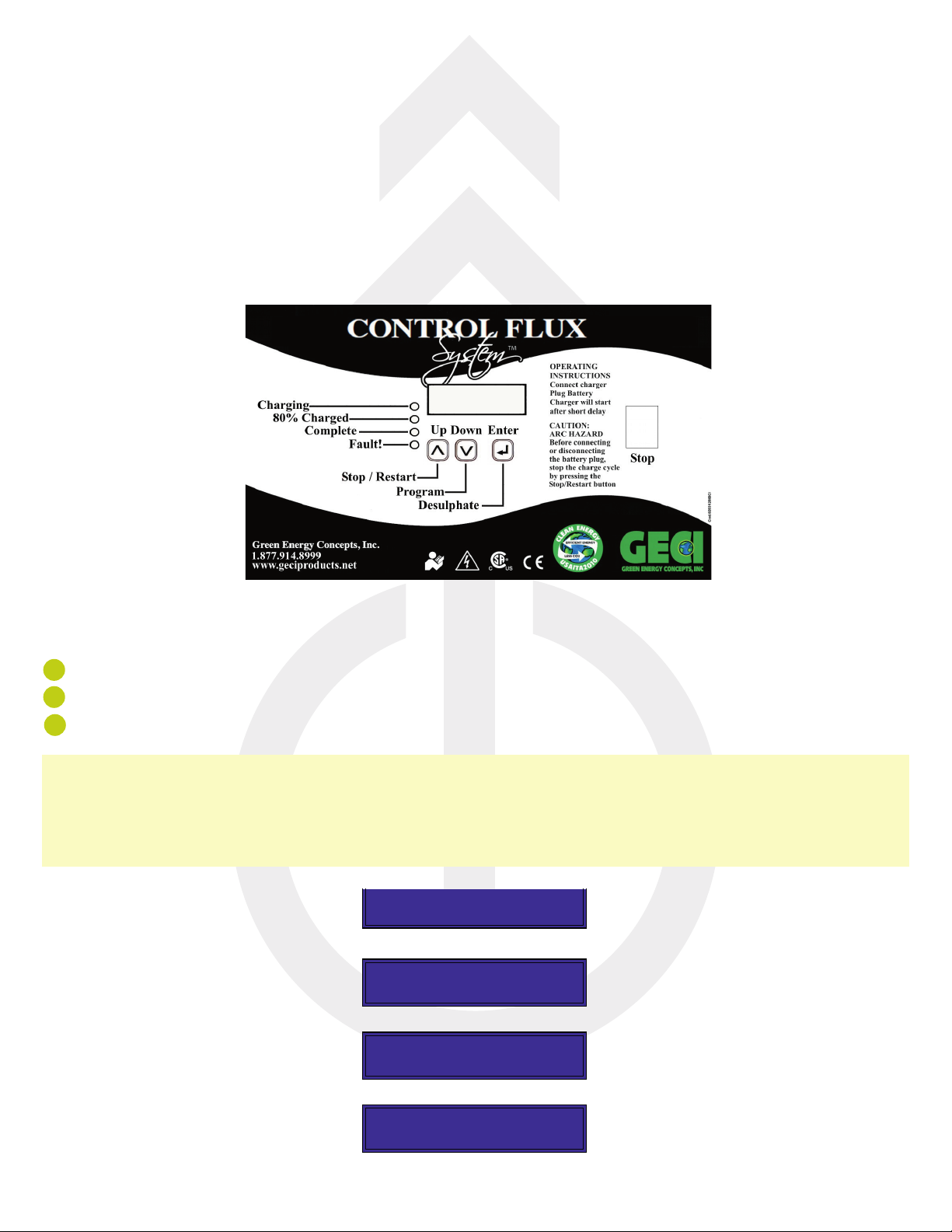
The operator can every time interrupt the standard charging and enable with a easy
procedure a special desulfation cycle. During the charging the operator can press Enter few
seconds and the display shows a desulfation menu, in this menu the operator can select the
time during of desulfation and the type of restart of desulfation, infact sometimes it is
strategic important to complete a standard charging after a completed desulfation cycle.
IBCI BLACK DIAMOND
User's Manual
EQ
UA
LIZE
C
Y
C
LE
– AU
TO
MA
TI
C (c
lo
ck m
od
e)
At the end of the charge, if the battery is left connected to the charger for a sufficient time,
the charger activates the Equalize cycle automatically, based upon the programmed
schedule.
If the charge cycle ends outside of the programmed Equalize time window, the charger
remains in stand-by mode, and the display shows the message:
DELAYED EQUALIZE
DAY TIME
Where DAY and TIME represent the beginning of the programmed Equalize time window.
EQ
UA
LIZE
C
Y
C
LE
– MANUA
L
During the charging of the battery the operator can scroll the menu of the display, and he can
force a EQ manual cycle at the end of this cycle.
FORCE MANAUL EQ
ENABLED
DESU
LF
A
TIO
N
The operator can every time interrupt the standard charging and enable with a easy
procedure a special desulfation cycle. During the charging the operator can press Enter few
seconds and the display shows a desulfation menu, in this menu the operator can select the
time during of desulfation and the type of restart of desulfation, infact sometimes it is
strategic important to complete a standard charging after a completed desulfation cycle.